乐高搭建合集(卷四·科技指南续章)— 链条滑轮至动力系统
卷四续章第一部分:链条与滑轮系统、杠杆与连杆机构、自定义机械方案、气动系统、气动装置、结构加固
chains
The LEGO chain system has been present in the Technic line since 1979, and despite its rarity, it’s unlikely to go out of use. The chain consists of small, rigid links that can be connected so that every link can be tilted relative to the next one (see Figure 6-2). In this way, we can create a flexible but rigid chain of any length, which can be wrapped around gears. Figure 6-3 shows the size of the LEGO chain compared to a brick. You may also recognize the chain link as similar to the LEGO track link (see Figure 6-4), which is used for tracked vehicles.
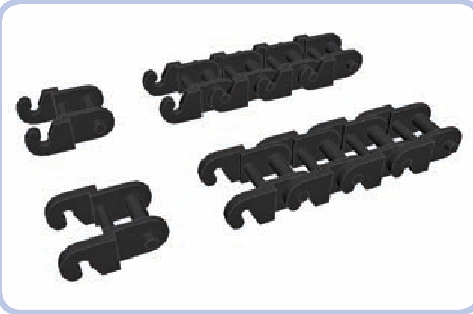
Figure 6-2: A single chain link and a section of four connected links, shown with slots facing upward and downward. In theory, the chain is less likely to come apart when its slots face the gear, but in practice, the difference is negligible.
Figure 6-3: An individual chain link is very small and practically impossible to combine with any other type of LEGO piece.
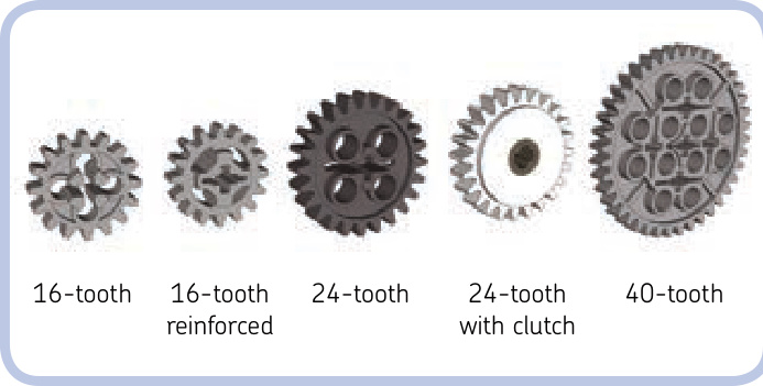
Figure 6-5: All the chain-compatible gears
Figure 6-4: The chain link (left) is similar to the LEGO track link (right) and can be combined with it. To learn more about tracks, see Chapter 16.
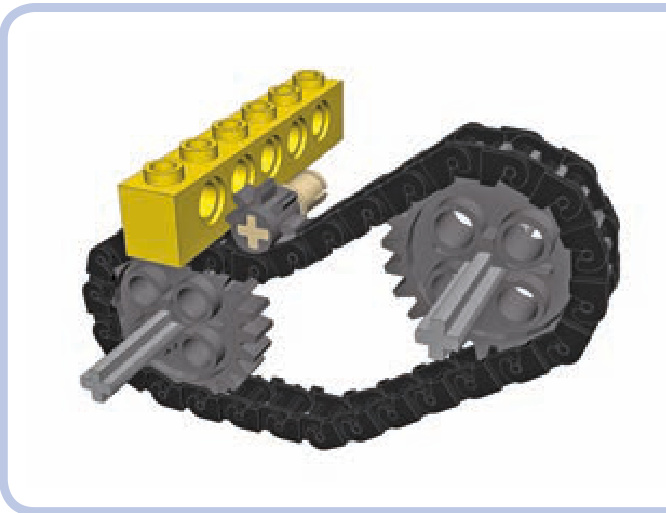
Figure 6-6: The 8-tooth gear also works with a chain but cannot drive it due to its small size. It can still be used as an idler gear, adapting the shape of the chain to the surrounding structure.
Five different gears work with the chain, as shown in Figure 6-5. While the 8-tooth gear can work with the chain, too, it cannot drive the chain as it’s simply too small (see Figure 6-6). Also note that by using the 24-tooth gear with clutch, you can make a chain slide when its output is stopped (for example, under load), meaning that the chain will behave just like a rubber band would over pulleys. Chains can also be wrapped around turntables to drive them, but they are rarely used this way as there are other, much less spaceconsuming methods of driving a turntable (for example, with a worm gear or an 8-tooth gear).
Even though the chain is rigid, it has a degree of elas ticity because the links are made of thin material. This allows us to adjust the tension of the chain. In general, the chain should not be very tight, as a tight chain is more likely to come apart under torque. Some play in the chain is therefore desired. The section of the chain that makes contact with
the gear has no play; rather, the play of a chain accumulates between the gears, usually in the lowest section of the chain due to gravity (see Figure 6-7). This play allows the system to withstand more force and becomes a problem only when it’s large enough to decrease the chain’s area of contact with the gears, increasing the risk of links skipping their teeth, or when it’s large enough to come in contact with the structure around the chain, where it can catch. When dealing with chains longer than 20 links, it’s a good idea to add 1 extra link just to lower the tension. Soft shock absorbers can be used to add a bit of tension.
The chain can be used to change the gear ratio by simply connecting two gears of different sizes. Linking two gears via a chain works exactly like directly meshing them: The gear ratio is equal to the number of follower gear’s teeth divided by the number of driver gear’s teeth. For instance, by using a chain to drive a 24-tooth gear with a 16-tooth
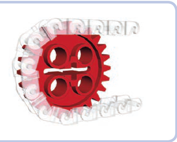
Figure 6-7: A close-up view of the chain wrapped around a gear shows that each link occupies two teeth. The section of the chain that has contact with the gear has no play in it, and its elasticity is minimized.
Figure 6-8: One major advantage of a chain (left) is that it does not require reinforced structure around it to handle high torque, unlike gears meshed directly (right).
gear, we obtain a 16:24 ratio, which can be reduced to 1:1.5, just as in a direct connection. And in the same way, the ratio of a chain system is not affected by idler gears. The only difference is that the chain keeps all the gears it’s wrapped around rotating in the same direction, with the exception of idler gears that are located outside the chain rather than inside it (see the idler gear in Figure 6-6). Note that you can use one chain to drive several follower gears of various sizes, creating a different ratio for each of them.
The important characteristic of a chain is its behavior under torque. When a high torque is applied to gears meshed directly (shown at left in Figure 6-8), it pushes them apart, which may cause their teeth to skip. But when a high torque is applied to gears connected with a chain, it pulls them together. This means that a chain has an advantage in hightorque applications: Gears connected with a chain don’t need a reinforced housing—the chain is something of a structural reinforcement itself.
pulleys
Pulleys are circular LEGO pieces designed to work with rubber bands or strings. They are distinguished by a groove around the rim, and there are only four types, as shown in Figure 6-9. Other LEGO pieces can be used as pulleys, too, but without a groove, they don’t hold rubber bands or strings as securely. Note that many wheels without tires can also be used as pulleys.
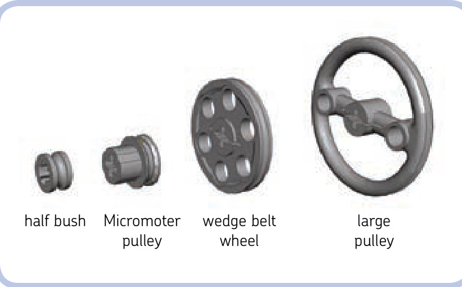
Figure 6-9: All four LEGO pulleys
The two most common pulleys are the regular half bush and the wedge belt wheel (so named because of its resemblance to real-life wheels designed to work with wedge belts, which we replace with rubber bands). The large pulley is less common, and the Micromotor pulley is the rarest, as it was originally meant to appear only with the LEGO Micro motor. When we connect two pulleys with a rubber band or a string, we create a gear ratio between them, just as we do in a chain system. The ratio depends on the proportion of their driver and follower diameters, which are shown in Figure 6-10. By driving a wedge belt wheel with a half bush, for example, we get a 21:5.8 ratio, which is equal to 3.6:1. And by driving a Micromotor pulley with a large pulley, we get a 9:32 ratio, which is equal to 1:3.55.
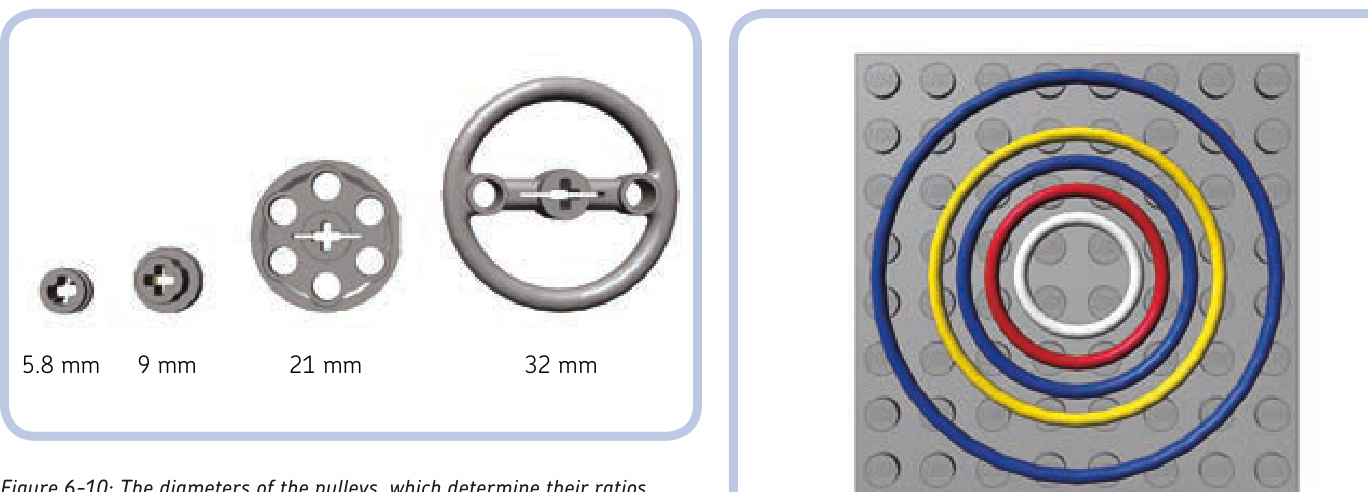
However, ratios between pulleys are less reliable than ratios between gears because there is no solid connection between driver and follower, just an elastic rubber band or a string that can slip, extend, or retract under load, thus altering the ratio. We can actually use this lack of a solid connection to our advantage—for instance, such slippage could prevent a motor from stalling. The diameter-based calculation should, therefore, be considered just an approximate value. The effective ratio depends on a number of factors, including the torque transferred and the tension of the element connecting the pulleys, and it varies rather than staying at one fixed value.
Using pulleys with strings is the subject of the next section. For now, we will focus on rubber bands. It’s perfectly possible to use any kind of thin rubber band, but LEGO actually has its own rubber bands, which work noticeably better. The rubber bands found in Technic sets are made of a high-quality silicone that rarely breaks and stays elastic for years, and they have a round cross section that fits pulleys grooves better than the square cross section of ordinary rubber bands.
The pulley-dedicated LEGO rubber bands come in five sizes from a -stud band to a -stud band. Other than size and color, the bands are identical, and each of them can be stretched to a larger size, with the bigger bands able to stretch more than the smaller ones. The various bands and their most popular colors are shown in Figure 6-11.
The general behavior of two pulleys connected with a rubber band is very similar to that of two gears connected with a chain: The rubber band acts as a belt, keeping all the pulleys inside it rotating in the same direction. Its shape can be changed with idler pulleys, and it pulls pulleys together when subjected to high torque. One band can also be used to drive several follower pulleys of various sizes by a single driver pulley, effectively creating a different ratio for each of them.
Figure 6-11: LEGO rubber bands come in five sizes, with diameters of 2, 3, 4, 5, and 7 studs. This figure also shows the most common color for each size.
The main difference between rubber band and chain drive systems is that the rubber band should be as tight as possible because any play can stop it from transferring drive or even make it fall off the pulleys. Slippage in a pulley system isn’t entirely negative—the fact that a band can slip when the follower pulley is stopped or blocked eliminates the need for a clutch of any kind. Note that when tight enough, the LEGO rubber bands can transfer surprisingly high torque without slipping, although they are generally considered less reliable than gears in high-torque applications. One problem is that bands are more likely to break, which can be disastrous when dealing with high torque.
Another advantage of pulley systems is their small size and thickness. The two most common pulleys—the half bush and the wedge belt wheel—are only a half stud thick, allowing two pairs of pulleys to fit where only one pair of gears would, as shown in Figure 6-12. That makes them a better choice than gears when space is limited and torque is low. Moreover, as long as the bands don’t slip, they create practically no backlash, regardless of their number, which is a huge advantage over gears in mechanisms that need to react quickly and accurately. Finally, they are practically noiseless.
Also note that the band is more flexible than the chain and can be bent in any direction, allowing you to create mechanisms that are just not possible with a chain, such as pulleys that can be driven at an angle (see Figure 6-13).
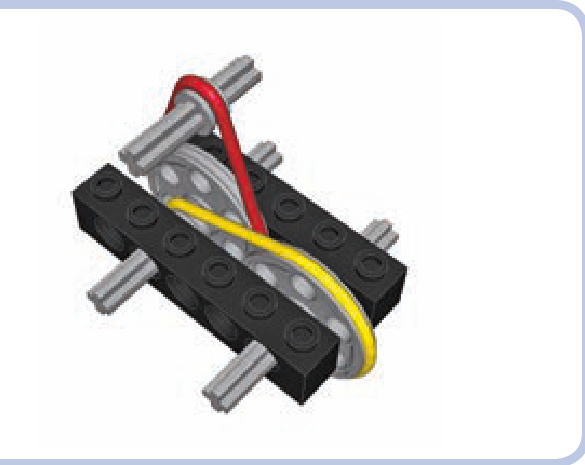
Figure 6-12: Two pairs of pulleys can fit into a 1-stud-wide space, which would be filled entirely by a single pair of gears.
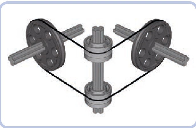
Figure 6-13: Two pulleys are connected by a rubber band at an angle, with two freely rotating rims on a vertical axle used as idlers to guide the band.
string and pulley systems
Using pulleys with strings is different from using pulleys with rubber bands. You can, of course, tie string into a loop and wrap it around two pulleys, but it won’t work as well because it won’t be as tight as a rubber band—string is simply less elastic and has much less grip. While rubber bands are used to transfer drive between two or more pulleys, string is best used to transfer the actual movement, that is, the displacement itself.
A perfect example of such a system is a winch in a crane, where string is wound on a reel and rotating the reel makes it pull loads up and down through a system of pulleys, as shown in Figure 6-14. In this case, the reel is the driver, and the movement is transferred to the hook at the end of the string. Without pulleys, the reel would have to be located on top of the crane, directly above the load. With pulleys, the string can be guided from the top of the crane to the back of it, where the reel is easily accessible and acts as the crane’s counterweight.
There are numerous examples of mechanisms using string to transfer movement, including drawbridges, window blinds, and even cable railcars (where a car literally attaches and detaches to a moving cable to travel). However, pulleys can do more than guide movement.
Pulleys and string can be combined into systems that realize mechanical advantage. Mechanical advantage is a measure that shows how much a given mechanism amplifies the force we apply to it. For example, a mechanical advantage of 2 means that the force is amplified twice. This is exactly the kind of speed/torque transformation we have discussed when dealing with gears, and mechanical advantage is simply another way of describing a ratio. So, a mechanical advantage of 2 is simply a ratio of 2:1.
The idea of mechanical advantage is well illustrated by the crane example from Figure 6-14. Let’s assume that we have already installed in the crane a system of pulleys that grants us a mechanical advantage of 2. This simply means that we have to apply half the force for twice as long—and that’s because amplification of the force comes at the cost of the extra length of string to wind up. For example, to lift 100 grams of load 1 meter, we have to rotate the reel long enough to wind up 2 meters of string using only enough force to lift 50 grams. We trade torque for speed, and it works to our advantage because the amount that we can lift is usually more important than how fast we can lift it. With enough mechanical advantage, we can lift or move any load, no matter how heavy—its weight affects only the amount of time it will take. (Obviously, it also requires a structure strong enough to support it.)
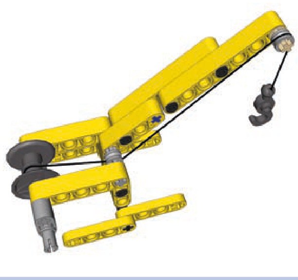
Figure 6-14: A simple crane uses a winch to pull a load on a hook up and down. The movement is transferred through a string, which is guided from the reel to the top of the crane by two half bushes acting as idler pulleys.
Pulley systems that realize mechanical advantage are usually installed just between the top of a crane and its hook. The invention of such pulley systems is attributed to ancient Greeks, and the systems were refined by ancient Romans. It is estimated today that the most advanced Roman cranes allowed a single person to lift up to 3 tons of load, which is quite impressive for simple machines made mostly of wood. This load capacity could be multiplied by using a number of cranes together to handle a single load. Many of the ancient buildings we admire today could not have been created without this invention that allowed human power to move extremely heavy objects.
A pulley system typically consists of at least one pulley that is fixed above the load and stays in place—for example, on the top of our crane—and at least one pulley that moves together with the load—for example, by being attached to the hook of our crane, as shown in Figure 6-15. So, there are two groups of pulleys, one fixed and another moving, and each can consist of many pulleys.
The way the two groups of pulleys are connected with string and how many times they are connected determines the mechanical advantage they provide. There are three categories of pulley systems, each with groups of pulleys connected in different ways, and we will discuss them starting with the simplest one.
simple pulley system
The simplest pulley system consists of two groups that are identical. The upper group is the fixed one. The string goes over the upper group’s first pulley and then comes downto the lower group, which is moving, and wraps around the lower group’s first pulley. Then it comes back to the upper group and is tied to it, or it can be wrapped around a second pulley and repeat the arrangement between the first two pulleys. This means that the string can’t be tied directly to the hook after it comes from the first upper pulley, which
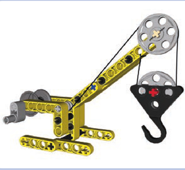
Figure 6-15: Our simple crane equipped with a pulley system. Two groups of pulleys are used, each consisting of a single pulley: The upper one stays on top of the crane, and the lower one moves up and down with the hook. This particular arrangement of string between the pulleys grants a mechanical advantage of 2.
is the main difference between the simplest pulley system and the lack of any such system, as Figures 6-16 and 6-17 show.
As you can see in Figure 6-17, the simplest pulley system has two sections of string connecting the two groups. This means that in order to lift the load, we have to wind up twice as much string as without this system, but using only half the force. The weight of the load is reduced twice at the cost of more string to be wound. There’s no free lunch: We are trading time for work, having to do less work but over a longer period of time.
But let’s consider what happens if we add another section of string between the two groups. We will need one more pulley to prevent the sections from getting tangled up with one another, as shown in Figure 6-18.
As you see, the string is now tied to the lower group, but only after it goes through three pulleys: two upper ones and one lower one. Three sections of string connect the two groups, granting a mechanical advantage of 3. We need to wind up three times as much string but use only one third of the force. By now you have probably guessed that the number of sections of string connecting the groups determines the mechanical advantage they realize.
These simple pulley systems are commonly used in sailboats and have various names depending on how many sections of string connect the two blocks. The system with two sections is called a gun tackle, and the system with three sections is called a luff tackle. Other systems, shown in Figures 6-19 to 6-21, have up to six sections of string. With more sections, the whole system becomes less and less efficient, as each pulley creates additional friction and the significant length of string in the whole system is prone to stretching under load.
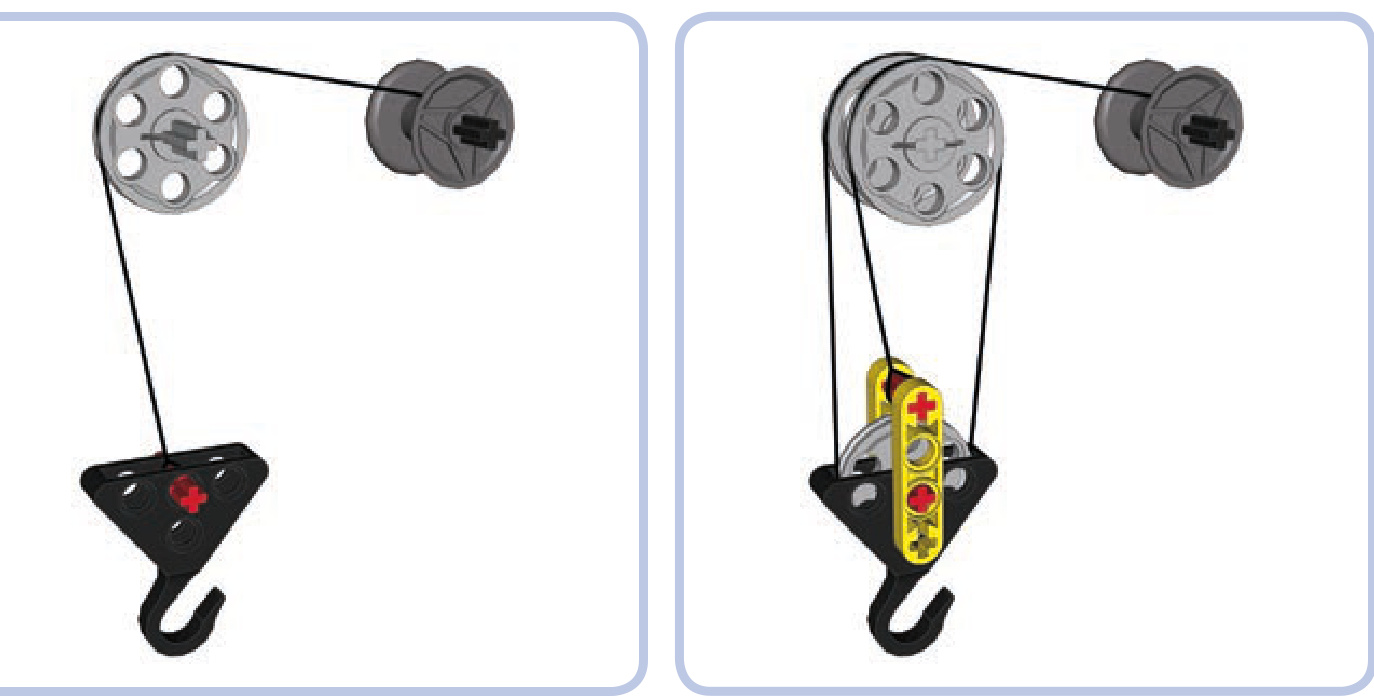
Figure 6-16: This arrangement has an upper group with a single pulley and no lower group. The string that comes off the pulley is tied directly to the hook. No pulley system is created, and no mechanical advantage is gained.
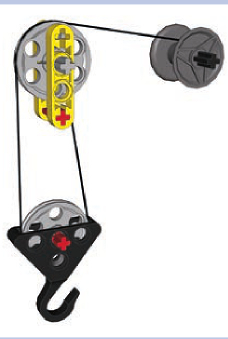
Figure 6-17: This arrangement has two groups, each with a single pulley. The string comes off the upper pulley and around the lower pulley and is then tied to the element that is part of the upper group and remains fixed to it. It’s the simplest pulley system, with a mechanical advantage of 2.
Figure 6-18: A pulley system with three sections of string between the groups. The upper group has string coming through it twice and hence two pulleys to prevent the string from getting tangled up. The string is then tied to the red axle in the lower group. This arrangement grants a mechanical advantage of 3.
differential pulley system
Despite its name, this type of pulley system does not use a differential gear. Instead, it uses an upper group with two independent pulleys that can rotate at various speeds in opposite directions. This is made possible by using two separate axles, one for each pulley, or by replacing one of the pulleys with some circular LEGO piece with a pin hole rather than an axle hole, as shown in Figure 6-22.
As you see, the lower group is fairly simple, while the upper one includes two pulleys of various diameters, one made of a wedge belt wheel and another made of a small rim (#42610). The rim has a pin hole, so it can rotate freely on the axle, regardless of the speed and direction of the other pulley, and it has a deep central groove with an inner diameter of roughly . The arrangement of the string is no less interesting: It’s tied in a loop, first coming off the reel, going over the large upper pulley and the lower pulley, and then coming back to be wrapped around the small upper pulley. Upon coming off, it’s tied to the section of string between the reel and the large upper pulley.
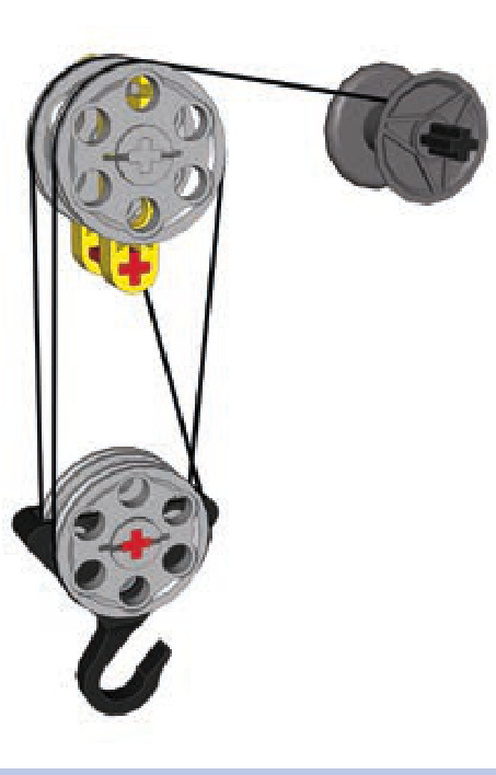
Figure 6-19: This system, called double tackle, grants a mechanical advantage of 4.
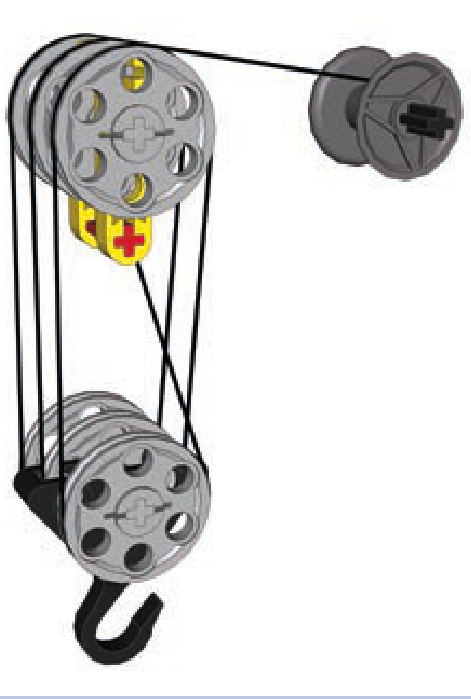
Figure 6-21: This system, called threefold purchase, grants a mechanical advantage of 6.
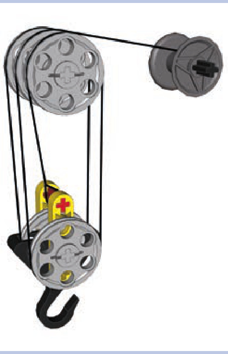
Figure 6-20: This system, called gyn tackle, grants a mechanical advantage of 5.
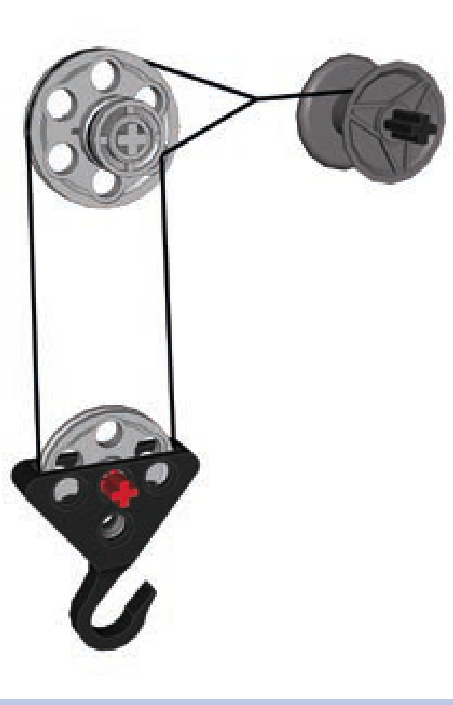
Figure 6-22: Differential block and tackle with two independent pulleys of different diameters in the upper block
When we rotate the reel, it pulls the string on both the large and small upper pulleys, making them rotate in opposite directions at various speeds. The difference in speeds is balanced by the rotations of the lower pulley. The interesting thing is how much mechanical advantage we can gain in this system.
If is the radius of the large upper pulley and is the radius of the small upper pulley, then the mechanical advantage of the whole system is equal to
In our example, is 10.5 and is 4.5, which gives a mechanical advantage equal to , which is 3.5. As you see from this formula, the mechanical advantage is bigger if the difference in the upper pulleys’ sizes is very small. But the pulley sizes cannot be the same because that would stop the lower group from moving up or down.
Let’s check the mechanical advantage given by other pulley combinations. For example, with the Micromotor pulley and a half bush , we can get , which is equal to 5.63—quite a result from such small pieces. The combination of another freely rotating rim (#56902), shown in Figure 6-23, with a deep central groove and an inner diameter of , and the Micromotor pulley grants a mechanical advantage of , which is equal to 20.
The differential pulley system allows us to easily obtain a high mechanical advantage. The travel of its lower group, however, is limited by the distance between the point where the string is tied to make a loop and the reel (for lifting) or upper pulleys (for lowering). This means that in order to lift loads very high, a long distance between the reel and the upper pulleys is needed.
power pulley system
The power pulley system is the most complex and most effective of the three systems. It’s distinguished by having one upper group and several lower groups that are connected in series, with the hook attached to the last one, as shown in Figure 6-24.
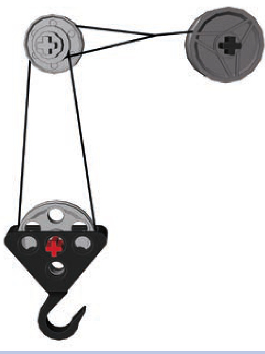
Figure 6-23: A differential pulley system with upper pulleys made of a freely rotating rim and a Micromotor pulley. There is only a difference in the radius inside the grooves of the pulleys, resulting in a mechanical advantage equal to 20.
As you see, this system starts with one section of the string (black) coming off the reel, going through the upper pulley, going through the pulley of the first lower group, and then being tied to part of the upper group. Then the lower group has another section of string (green) attached to it. This string goes through the pulley of a second lower group and is then tied to part of the upper group, just like the first string’s section. This series of repetition can continue until the final lower group, which has a hook attached to it and handles the actual load. In Figure 6-24, the hook is present on the 4th lower group, but it could just as well be present on the 20th one. Note that by moving the points where strings are tied to the upper group away from its pulley (to the left in Figure 6-24), it’s possible to make the lower groups travel not only up and down but also forward and backward.
The mechanical advantage of the power pulley system is equal to 2n, where is the total number of lower groups. This means that the mechanical advantage increases rapidly with the number of lower groups, starting with 2 for one group, 4 for two groups, 8 for three groups, 16 for four groups, and so on. This may not sound impressive compared to the 22 we achieved with the differential pulley system, until you realize that the advantage in the power system exceeds 1,000 with 10 lower groups and 1 million with 20. And there is no technical limit to how many lower groups can be used, although just like the other systems, this one becomes inefficient with many pulleys adding friction and a lot of string stretching under load.
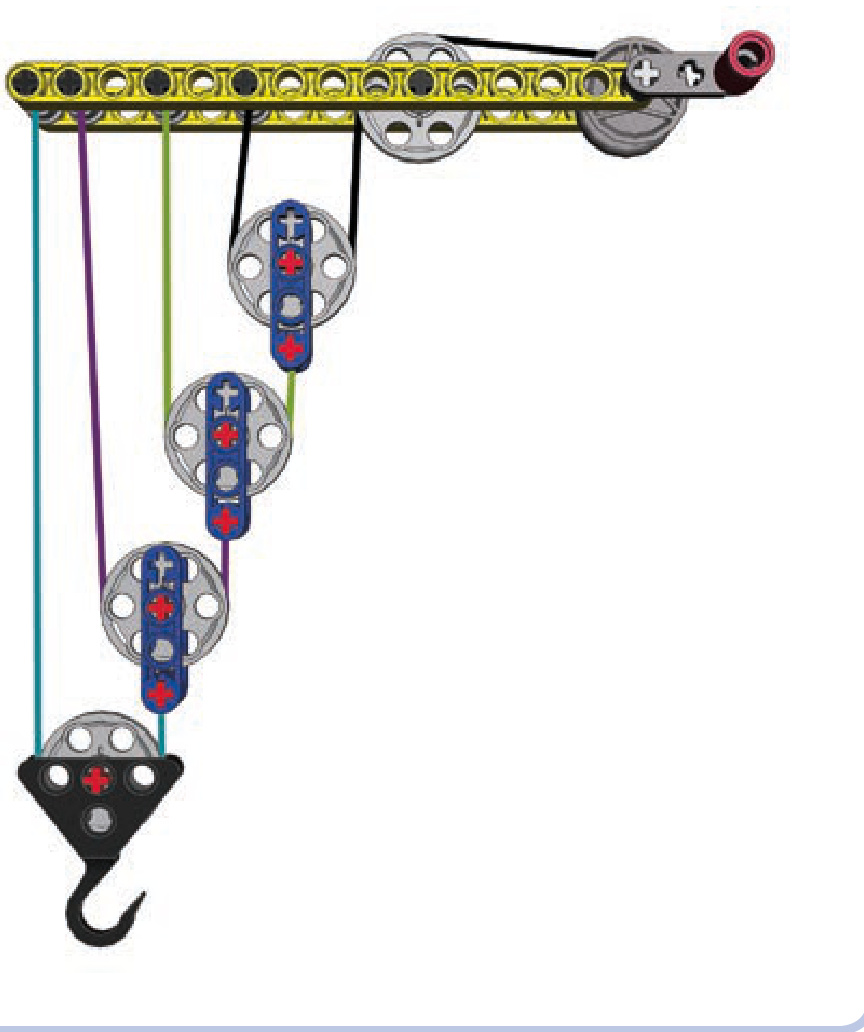
Figure 6-24: The power pulley system consists of one upper group and a number of moving lower groups connected in series. There are four lower groups here, granting a mechanical advantage of 16.
levers and linkages
Levers and linkages are some of the simplest machines and form the basis for countless more complex mechanisms. While levers are mostly used to provide a mechanical ad vantage that allows us to move heavy loads, linkages are mostly used to transform one type of a motion into another. Both are common in everyday life: If you have ever played on a seesaw or used pliers, you have relied on levers and linkages.
levers
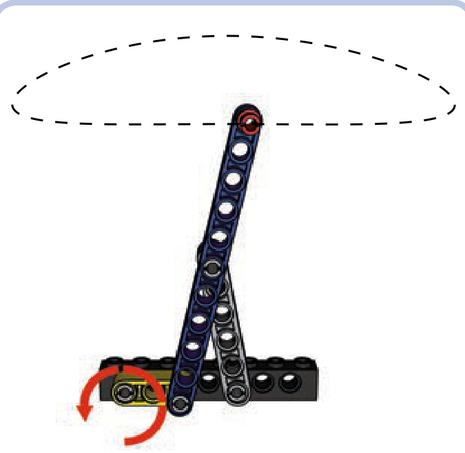
A basic lever is simply a beam that has one point of support in the form of a hinge or a pivot, as shown in Figure 7-1. We will call this point a fulcrum. A lever also has input and output forces. We will call the applied, or input, force the effort and the reaction force the load. Finally, we will call the sections of the lever between its fulcrum and its ends arms.
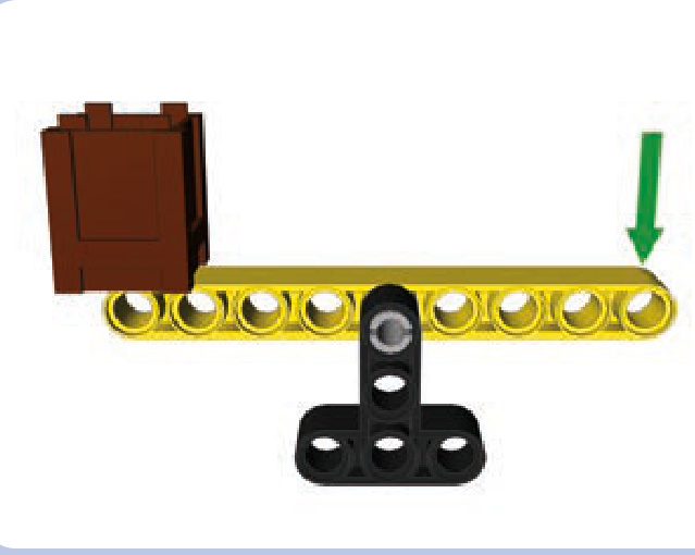
Figure 7-1: A simple lever, consisting of a beam (yellow) supported by the fulcrum (black). The brown crate is the load and the green arrow represents the effort. When effort is applied downward, the load is lifted up.
When a lever provides a mechanical advantage, our input force is amplified. But that increase in force does come at a cost, just as it does with all other simple machines. A lever with a mechanical advantage of 2 allows us to move the load using half the force it would take without the lever but covering only half the distance (traveling at half the speed).
The mechanical advantage of the lever depends on the distances between the fulcrum, the load, and the effort. The so-called law of the lever states that the mechanical advantage of a lever is equal to , where is the distance between the effort and the fulcrum, and is the distance between the load and the fulcrum. For example, for the lever shown in Figure 7-2, (indicated by the blue arrow) is 5 studs long, and (indicated by the red arrow) is 3 studs long. Therefore, the mechanical advantage of this lever is , or 1.67. This means that in order to lift of load 1 meter with this lever, we have to apply the
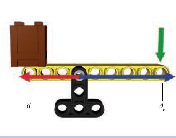
Figure 7-2: This lever has a mechanical advantage of , or 1.67, because the distance between the fulcrum and the effort is 5 studs and the distance between the fulcrum and the load is 3 studs.
effort needed to lift and move the end of the lever 1.67 meters. The mechanical advantage still benefits us because we’re trading time, which we have plenty of, for force, which is limited.
The law of the lever also means that the force applied to the arm of a lever is inversely proportional to the arm’s length. Therefore, it takes more force to move a lever with a short arm than it takes to move a lever with a longer arm. A lever with a 3-stud-long arm will take twice the force as a lever with a 6-stud-long arm to move the same load. The lever with the 6-stud-long arm, though, will move the load twice as far because of its longer length.
Figure 7-3 illustrates the distance/force proportion. We have a lever with a 3-stud-long arm and a 7-stud-long arm. If we apply force to the longer arm, the lever offers a mechanical advantage of 2.33 (7/3), and if we apply force to the shorter arm, the lever offers a mechanical advantage of 0.43 (3/7). If we put a load on the longer arm and a load on the shorter arm, the loads will balance each other.
Note that a lever can have equal and distances, resulting in a mechanical advantage of 1. This simply means that there is no mechanical advantage and the distance/force balance remains unaltered. Such a lever can still be useful, as it reverses the direction of movement (that is, by pushing down, you lift a load up).
Finally, note that a lever does not necessarily have to be a straight beam. It can be bent and work just the same. A simple crowbar is a good example of a bent lever (see Figure 7-4): It has a long arm, a short arm, and a central part that we put on the floor, thus creating a fulcrum. By shoving the short arm under the load, we are able to use the long arm to lift that load using less force than without the crowbar.
classes of levers
The positions of the fulcrum, the load, and the effort on a lever can vary. There are three possible combinations, which are called classes. Fortunately for us, the law of the lever is exactly the same for each class, meaning that the mechanical advantage is calculated in the same way for all of them.
The lever classes are as follows:
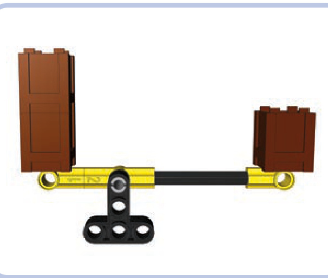
Figure 7-3: This lever has a mechanical advantage of 2.33, meaning that one of its arms is 2.33 times as long as the other one. Therefore, any load put on the longer arm can balance a 2.33 times heavier load on the shorter arm.
Class 1 (see Figure 7-5): The fulcrum is located in the middle of the lever and the load and effort at its ends. This is the only class of lever where effort and load are applied in opposite directions (that is, to lift a load up, you have to apply effort downward). Examples: a seesaw or a crowbar.
Class 2 (see Figures 7-6 and 7-7): The load is located in the middle of the lever and the fulcrum and effort at its ends. Example: a wheelbarrow, with the wheel being its fulcrum.
N Class 3 (see Figures 7-8 and 7-9): The effort is located in the middle of the lever and the load and the fulcrum at its ends. Because of this arrangement, the class 3 levers have a mechanical advantage of less than 1 and are used to trade force for distance rather than the other way around. This makes them useful when there is plenty of force that can be used to move the load over greater distance. Example: a boom of a crane elevated by a pneumatic cylinder attached to its middle.
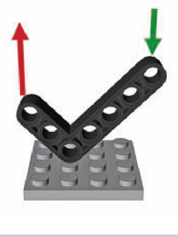
Figure 7-4: The bent beam can work just like a crowbar.
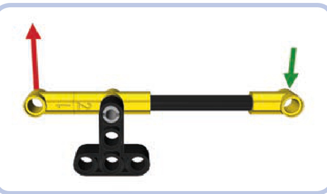
Figure 7-5: Class 1 lever with the fulcrum in the middle and the effort (green) and load (red) at its ends
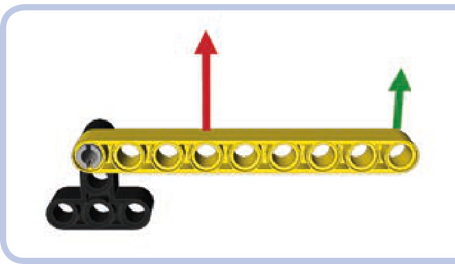
Figure 7-6: Class 2 lever with the load (red) in the middle and the fulcrum and effort (green) at its ends
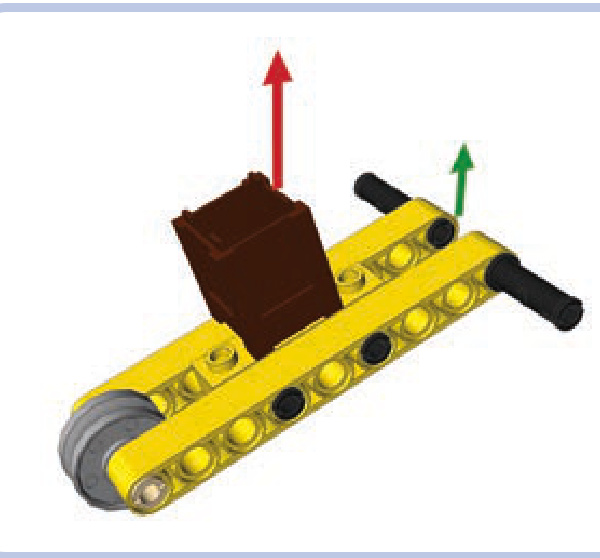
Figure 7-7: An ordinary wheelbarrow is an example of the class 2 lever, with its wheel being the fulcrum. The load is located in the middle of the wheelbarrow, and the effort is applied to the end of it. Wheelbarrows usually provide a mechanical advantage greater than 1, unless you apply the effort exactly where the load is located.
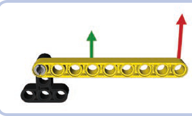
Figure 7-8: Class 3 lever with the effort (green) in the middle and the fulcrum and load (red) at its ends
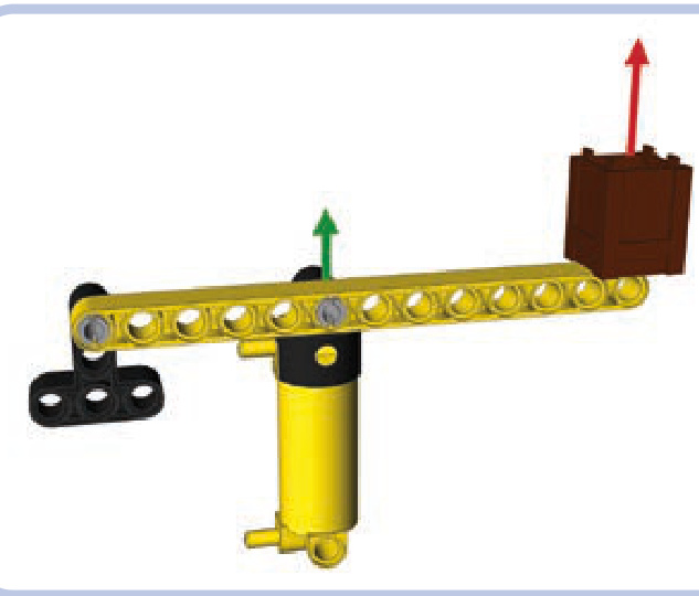
Figure 7-9: A boom of a crane is an example of the class 3 lever, with the load and the fulcrum at its ends and the effort applied to its center (in this case, by a pneumatic cylinder). Class 3 levers have a mechanical advantage less than 1, meaning that they require plenty of effort but can move loads over large distances. This is favorable when it comes to pneumatics, which can exert huge force but have limited reach.
from levers to linkages
An interesting thing happens when you connect ends of two identical levers located one above the other: The elements connecting their ends will maintain the same position as the levers move. This happens at every point in the levers’ range of movement, regardless of their length. We can use this system of parallel levers, also known as a 4-bar linkage, to our advantage.
As Figure 7-10 shows, we can expand our crane’s boom in Figure 7-9 by adding a parallel lever to it. This addition provides two advantages: First, we can move both levers by applying effort to only one of them because the elements
connecting them will transfer the movement from one to the other. Second, and more importantly, the element at the “load” end of the levers will move with the levers while maintaining constant orientation. This means that the load’s angle won’t change as it moves up and down with the levers, which is useful when moving loads that we don’t want to tip over.
Many kinds of machines—front loaders and telescopic forklifts, for example—use parallel levers to handle loads. The LEGO 8265 set, shown in Figure 7-11, is an excellent example of a front loader: Its bucket is connected to arms that form parallel levers. Note that a linear actuator on each side acts as the lower lever, and by extending or retracting, it controls the bucket’s height. When it extends or retracts to the point that its length differs from that of the upper levers, an additional linkage between it and the bucket keeps the bucket level. The same additional linkage allows us to tip the bucket with another linear actuator. The bucket’s orientation depends entirely on the lengths and locations of the levers.
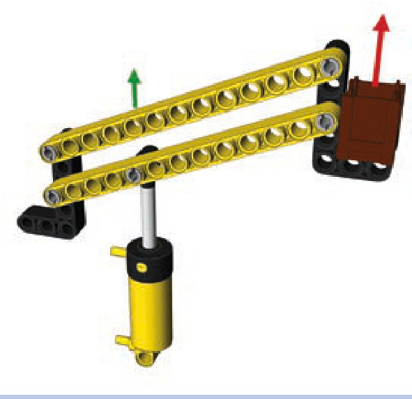
Figure 7-10: A boom of a crane made of parallel levers. The parallel levers ensure that the element on the end of the levers maintains constant orientation as the levers move it up and down.
For the orientation to be maintained, the two levers have to be of identical length, and their ends have to be connected with identical spacing, as shown in Figure 7-12.
Note that the levers connected in this way can’t make a full rotation: They limit each other, colliding at a certain point. Therefore, their rotation is limited to a certain range, which can be adjusted by locating the levers not exactly one above the other but with a small displacement, as shown
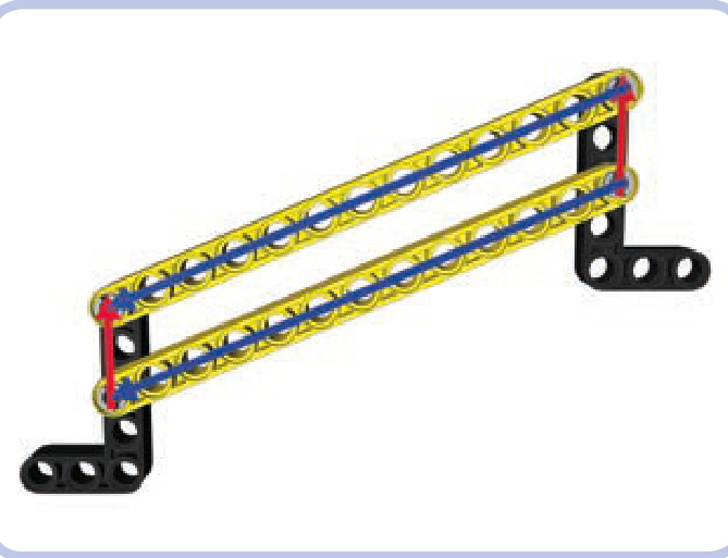
Figure 7-12: The parallel levers maintain the orientation of the elements at their ends only if the levers’ length and spacing are identical.
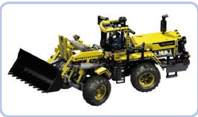
Figure 7-11: The LEGO 8265 set features a complex front loader whose arms (elevating the bucket) form parallel levers.
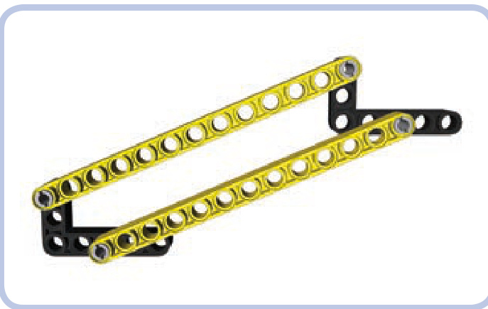
Figure 7-13: The parallel levers are displaced to adjust their range of movement. By moving the upper lever a little backward (left in the figure), we can increase the maximum reach upward at the cost of maximum reach downward.
Other variations are possible with a parallel-levers arrangement. For example, the element connecting the levers at the fulcrum can be rotated, making the element at the other end rotate at the same angle, as shown in Figure 7-15. This is one way to tip the bucket of our front loader.
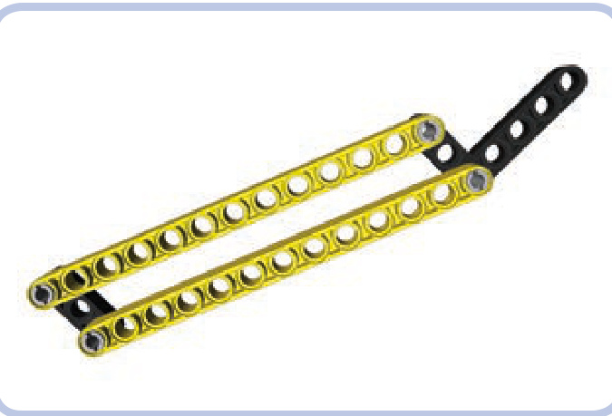
in Figure 7-13. Also note that the elements connecting the two ends of the levers don’t have to be identical, nor do they need to be set at the same angle—it’s only the angle and distance between the points of attachment that matter (see Figure 7-14).
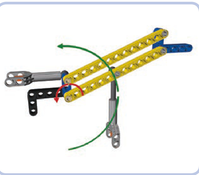
Figure 7-14: The functioning of the parallel levers relies on the positions of their points of attachment. These positions can be made identical on both ends using various elements set at various angles.
As Figure 7-16 shows, there is an interesting effect if the levers are not exactly parallel: Rotating the levers makes the element connecting their ends rotate slightly as well. This limits the levers’ range of movement but can sometimes be desirable—in particular, when we want the element at the levers’ end to be oriented differently in the lowermost and uppermost positions. This is the case with the LEGO 8460 Pneumatic Crane Truck set, where such an arrangement is used to control the stabilizing outriggers. This arrangement makes the outriggers nearly horizontal when lowered and nearly vertical when raised, effectively increasing their reach.
Finally, you can use the fact that the parallel levers rotate relative to the elements that connect them to your advantage. By putting gears on the axles that rotate together with the levers, we can transfer that rotation through these elements (for example, to another pair of parallel levers connected to it).
Figure 7-17 shows two pairs of parallel levers connected in such fashion—gears that transfer the rotation of one pair (left) to another (right). All the levers are identical and the gears maintain a 1:1 ratio, the result being that the element at the end of the series moves along a horizontal line. There is technically no limit to how many pairs of levers can be used in a series; the only constraint is the friction and the sum of the gears’ backlash.
linkages
Linkages are groups of rigid links connected by joints that allow them to perform certain restricted movements. They are mostly used to convert rotary or rocking motion into linear motion, allowing elements of various machines to move along straight lines. They can also be used to achieve mechanical advantage using the law of the lever. The lever is, in fact, the simplest linkage possible.
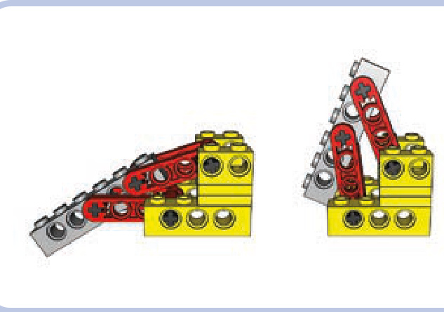
Figure 7-15: This boom variant uses one actuator to lower and raise the parallel levers (green arrow) and another to rotate the element that connects them at the fulcrum (red arrow), thus making the element at their other end rotate.
Figure 7-16: An outrigger mechanism from one of the LEGO mobile cranes uses levers that are not exactly parallel. The yellow part is the chassis, the levers are red, and the actual outrigger is grey.
Figure 7-17: Two pairs of parallel levers connected by gears are installed on the element between them. The gears make the pairs rotate in opposite directions, moving the parts at both ends horizontally.
Figure 7-18: Watt’s linkage consists of two long side links and one shorter central link. A rocking movement of any of the side links makes the central link move so that its center (marked by the red pin) follows a straight line.
Not e In all the figures of linkages here, beams in the same color are of the same length. A dark grey color is used to mark the supporting structure, which remains stationary and to which the linkage is attached, and red pins mark the point of the linkage that performs the desired motion.
The key advantage of linkages is that their movement remains restricted without the need for external guiding elements, as shown in Figure 7-18. This makes them convenient for many uses. In the real world, linkages are used to control the movement of suspension components. Note also that usually only one particular point of a linkage follows the desired movement, and we can use pins located at this point to transfer this movement elsewhere—for example, to the base of the element we want to move using the linkage. A nearly infinite variation of motions can be achieved by varying the lengths and positions of just three or four beams!
Chebyshev linkage
The Chebyshev linkage, also known as Tchebycheff’s linkage, consists of three links and is driven by the rocking motion of the lower links (light grey). This motion makes the central link (yellow) move so that its center (marked by the red pin) follows a straight line. The motion continues to the point at which the central link becomes vertical. The central link needs to be the shortest of the three to prevent it from colliding with the supporting structure (dark grey).
Hoeken’s linkage
Hoeken’s linkage consists of three links and is driven by the rotary motion of the shortest one (yellow). The proportions of the following three dimensions are crucial to make this linkage work: the length of the shortest link (yellow), the length of the medium link (light grey), and the distance between points of attachment to the supporting structure. The proportions should be 2 to 5 to 4. The longest link (blue) can be extended to any length beyond its upper joint. The tip of this link traces the shape of a flattened oval cut in half (the dotted line in the illustration), and the size of this oval is determined by the extended link’s length. A little less than half of this link’s movement is linear. Such an unusual motion pattern can be used, for example, to drive the legs of walking vehicles.
pantograph
A pantograph is a particular type of linkage with four links and two points, and its movement is quite interesting. In a pantograph, the point marked by the green pin mimics every movement of the point marked by the red pin, but on a larger scale. The difference in scale depends on the length of the longest link (light blue) and on where other links are attached to it (note that the longest link actually works like a lever).
The most interesting and popular use of this property is creating enlarged or reduced copies of drawings by attaching pens to both these points and “drawing” with one of them manually. This also works with handwriting; Thomas Jefferson used this method to duplicate his correspondence. Today, scaled copies can easily be created using a computer. However, pantographs still remain in use where certain tools require accurate manual control, as in engraving and sewing.
Peaucellier–Lipkin cell
The Peaucellier–Lipkin cell, also known simply as Peaucellier’s cell, consists of seven links and is driven by the rocking motion of the central link (yellow). Note that the spacing between the cell’s two points of attachment to the supporting structure needs to be equal to the length of the central link.
The Peaucellier–Lipkin cell works on the principle of inversion of a circle (with the central link tracing part of it), and it was one of the first linkages capable of producing perfectly linear motion. Its invention was crucial for the development of 19th-century industry and, most notably, for its use in steam engines.
Sarrus linkage
The Sarrus linkage consists of four links in two identical groups that are perpendicular to each other. All links are of equal length, and the linkage is driven by the rocking motion of both lower or both upper links. The advantage of the Sarrus linkage is that it can be used to lift the structure connecting the upper links, providing an impressive range of movement as seen in Figure 7-19). Note that the perpendicular links work in different directions and thus exert stress on each other, which is why they need to be very rigid and preferably several studs wide for the linkage to work properly.
The disadvantage of the Sarrus linkage is that it requires one link from one group to be moved simultaneously with a second link from a second group. In other
Figure 7-19: The Sarrus linkage’s minimum and maximum range of lift
words, the motion of the links needs to be mechanically synchronized. Figure 7-20 shows one of the simplest synchronization methods. Note that the Sarrus linkage can consist of three or four groups as well, but two properly synchronized groups are enough to provide stable movement of the upper structure.
Figure 7-20: This Sarrus linkage uses mated bevel gears to synchronize links between the two groups.
Scott-Russell linkage
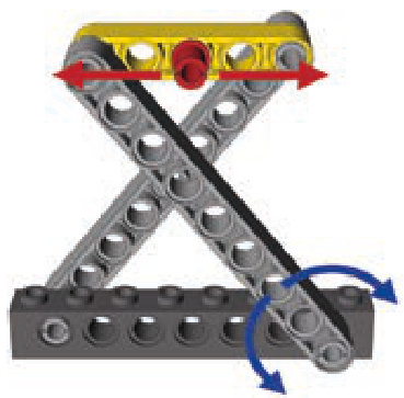
The Scott-Russell linkage consists of two links and is driven by the rocking motion of the shorter one (yellow). The longer link (blue) has one end attached to the supporting structure so that it can slide on it along a straight line. That makes the other end of that link move in a straight line as well. Both ends of that link move as if they were locked between guiding elements, but only one end actually is.
Note that the spacings between all joints of the linkage (marked by pins in the illustration) have to be equal. In this example, they are all equal to 3 studs.
scissor linkage
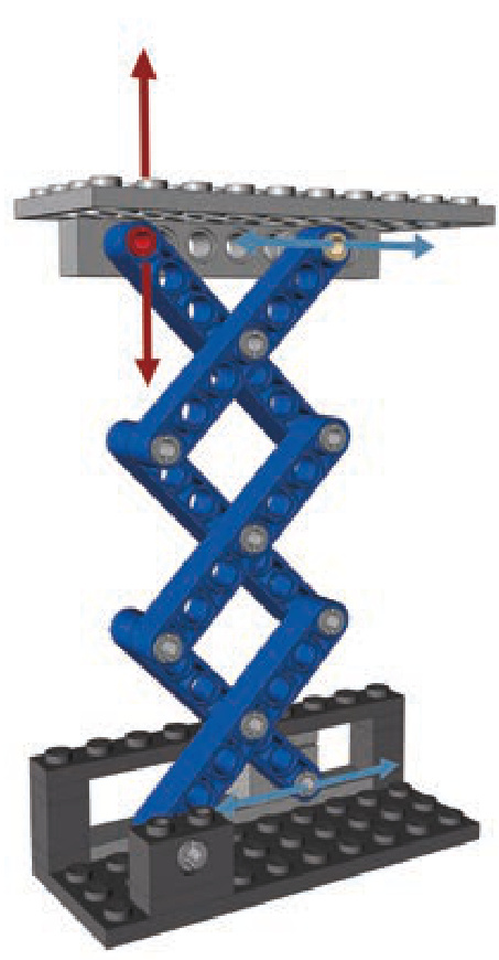
A scissor linkage, also known as a scissor mechanism, combines Scott-Russel and Sarrus linkages to create a compact mechanism capable of lifting with impressive range. It can consist of any even number of identical links— for example 2, 4, 6, and so on—and is driven by either the rocking motion of any link or by moving the end of the link that can slide within the supporting structure. Note that one of the top links also has an end that slides within the upper structure, but its movement can be restrained by simply making the upper structure’s weight rest on it. In the illustration, the end has an axle pin with a bush attached to support the upper structure while sliding.
The two key advantages of the scissor linkage, its range (shown in Figure 7-21) and its stability, combined with its compactness make it a very popular mechanical solution. For example, it appears in car doors to make windows move up and down; in so-called scissor lifts; and even in high-end computer keyboards, where it’s used to stabilize keys. There is no limit to how many links can be used in a scissor linkage, except that every joint adds extra friction. There are also no special length or distance requirements, except that all links have to be equal.
Figure 7-21: A comparison of the same 10-link-long scissor linkage in a fully retracted and a fully extended position
Watt’s linkage
Watt’s linkage (shown earlier in Figure 7-18) consists of three links: a short central link (light blue) and two longer side links (blue). The linkage is driven by the rocking motion of either side link. As the side links rotate, the central links move so that the mechanism’s center follows the dotted line, which remains straight most of the time. Note that while the ends of that line deflect to the left and right, you can limit motion of the linkage to the straight part only.
Watt’s linkage is sometimes used in suspension systems to keep suspension components moving up and down rather than sideways. In most configurations, its side links are two or even three times longer than the central link.
custom mechanical solutions
While the LEGO Group produces an incredible range of specialized Technic pieces, they won’t always meet our needs. Sometimes we’ll need to combine pieces to create mechanical solutions we find in the real world. This is the subject of this chapter: mechanisms that extend the functionality of your constructions beyond the limits of ready-made LEGO pieces. Here you’ll find mechanisms that transform one type of motion into another, that take basic LEGO lights and transform them into sophisticated signaling systems, and much more.
These mechanisms are fun to build just on their own as explorations of mechanical engineering concepts, but you’ll also find them quite useful when building larger models.
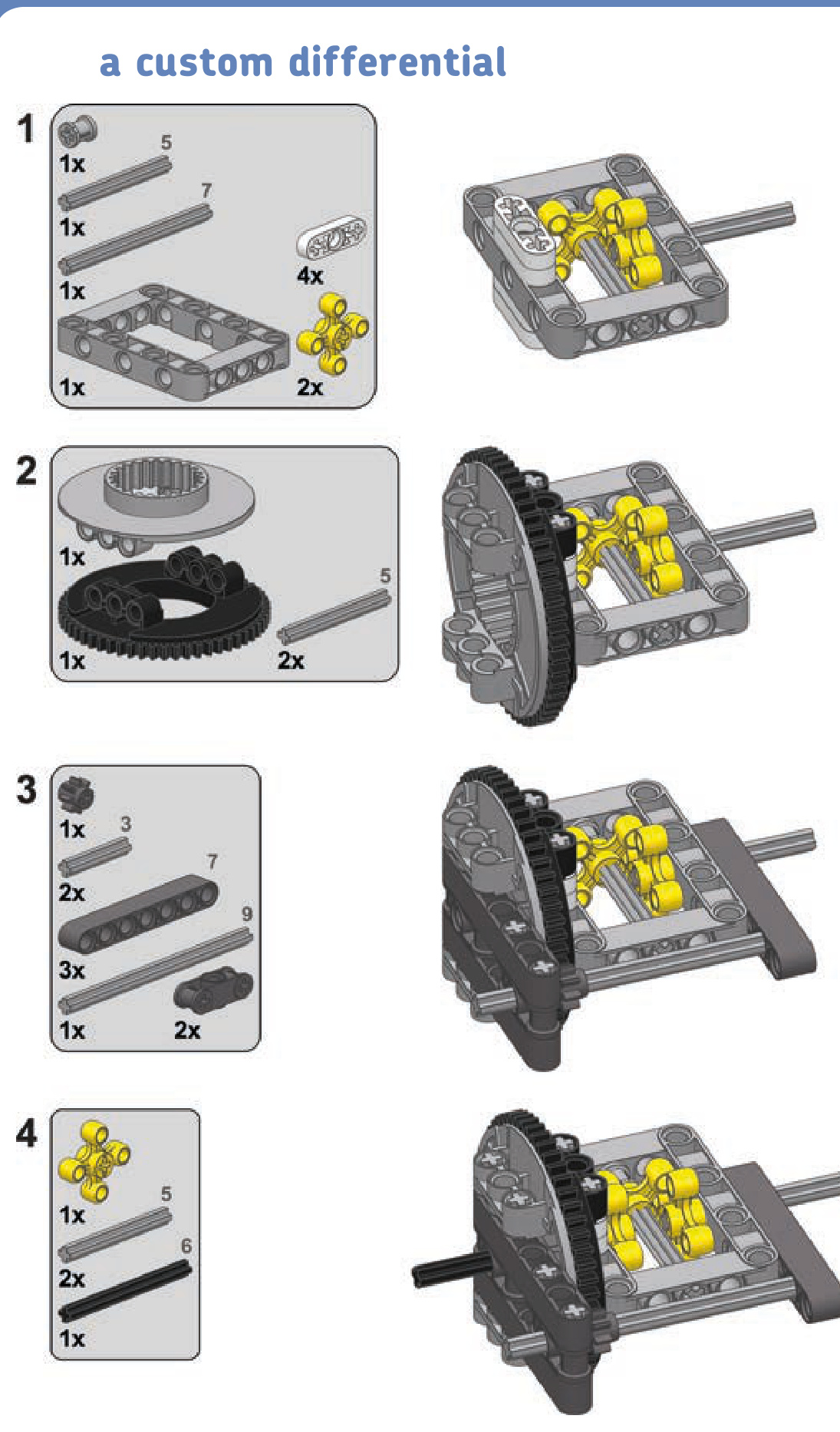
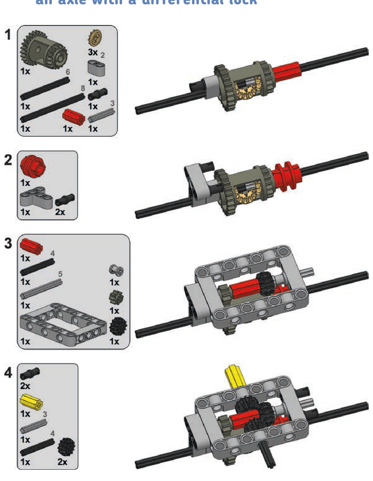
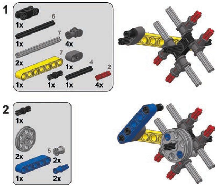
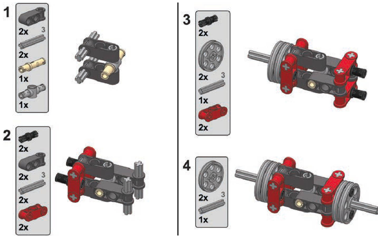
a stronger differential
Differentials are an essential part of every driven axle in a vehicle with wheels. They’re also important in large and heavy LEGO vehicles. The prebuilt LEGO differential consists of a housing with a ring gear and with places for two axles and three bevel gears inside, as shown in Figure 8-1. This is the mechanism that we’ll re-create, stronger and better.
Not e There are three variants of ready-made LEGO differentials. They are all discussed in Chapter 5.
In automobiles, a differential is located between the wheels. The differential’s housing is driven, and the differential transfers the drive to the wheels through its two output axles. Note that the differential transfers the drive from the housing through the central bevel gear, which is meshed with bevel gears on the two axles. The central bevel gear
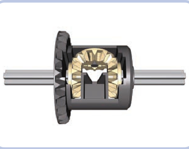
Figure 8-1: A ready-made LEGO differential, with the differential housing in dark grey, three inner gears in tan, and two output axles in light grey
can balance the drive between the output axles, meaning that it can drive one axle faster than the other. This ability to balance the drive enables the vehicle to turn smoothly. Figure 8-2 shows that the wheels of a turning vehicle travel along different arcs. As a result, the inner and outer wheels have to travel different distances. A differential is able to balance this difference by driving the outer wheel faster than the inner one.
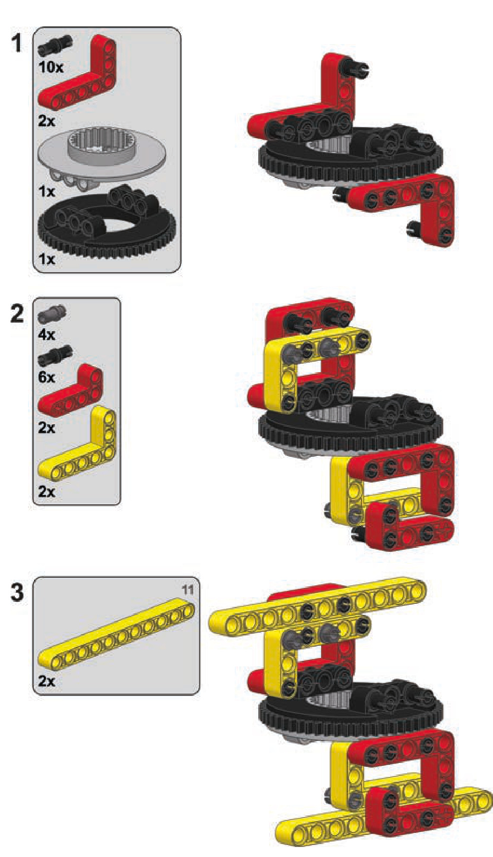
As ready-made LEGO differentials are torque sensitive and rarely appear outside of big, expensive sets, we can build our own differential using a large Technic turntable, as shown in Figure 8-3.
This kind of custom differential is much larger and much sturdier than a ready-made one. Using a turntable allows the mechanism to transfer drive to the differential without using bevel gears and instead using the much stronger knob wheel.
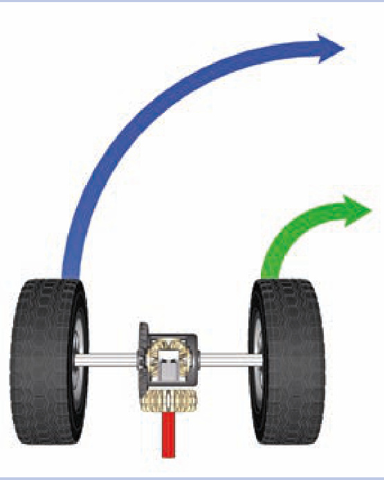
Figure 8-2: Differential in a turning vehicle. The red axle transfers drive to the differential housing, which then transfers it to the wheels.
At the same time, the turntable provides a robust mounting point, holding the differential firmly to the chassis.
It’s possible to build a vehicle without using differentials, but there are some disadvantages. Without a differential, at least one wheel will slip while cornering a turn, increasing friction and tire wear and impairing the vehicle’s maneuverability.
If there is no differential in a driven, nonsteered axle, that axle will also be prone to slipping while making a turn. This can actually be desirable if your intention is to build a vehicle whose rear end slides dramatically when turning. In the real world, small, lightweight vehicles, such as go-karts, are usually built without differentials because the advantages of a differential are not worth the increase in the drivetrain’s complexity.
If there is no differential in a driven and steered axle (like the front axle of a front-wheel-drive car), turning becomes much more difficult. The difference in the inner and outer wheels’ speeds while cornering is much greater in steered axles than in nonsteered ones, creating so much friction that it exerts significant stress on the drivetrain and can even stall the motor. At the same time, the minimum turning radius becomes larger because the wheels, forced to rotate at equal speeds, lose their grip.
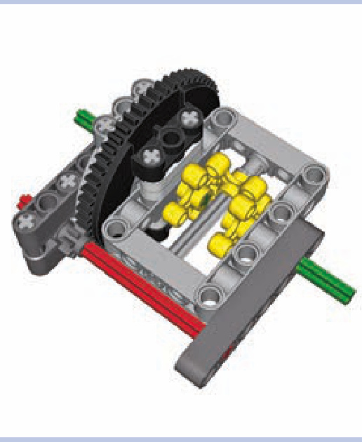
Figure 8-3: A custom differential made of a large Technic turntable connected to a studless frame. The input axle is shown in red, the output axles are shown in green, and the dark grey beams are parts of the chassis’s structure around the differential.
differential locks
With all the advantages of using a differential, there is also one disadvantage that is particularly important for off-road vehicles. As a differential transfers drive between its two outputs, it tends to transfer more of it to the less loaded one. This works fine when turning, but it can stop a vehicle entirely if one of the wheels slips or loses contact with the ground. A so-called slip situation occurs, in which the differential transfers all the drive to the wheel that has lost contact, completely stopping the one that’s still touching the ground. When this happens, we can use a differential lock to force the differential to drive both wheels, overcoming the slip situation.
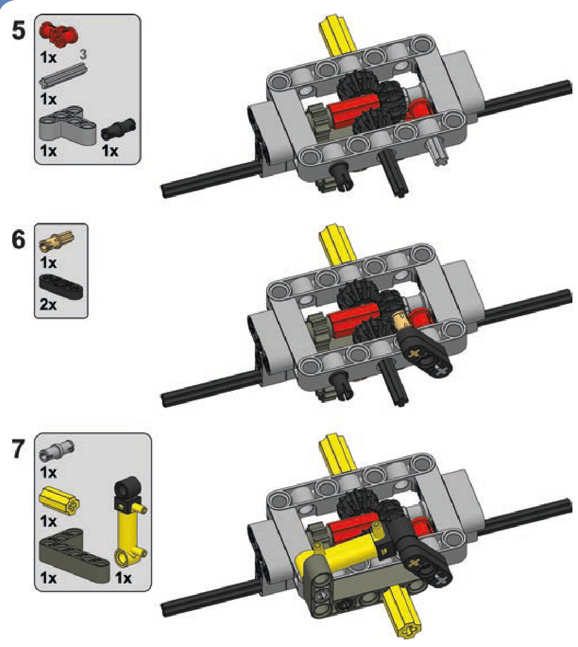
A differential lock joins a differential’s two outputs together, effectively disabling the differential so that it transfers drive but doesn’t balance it. It’s important to understand that a differential lock does not prevent a slip situation: The lock is used when a slip occurs and fixes the slip. This is because a differential lock and a differential can’t work at the same time. As a result, the differential lock should remain disengaged to allow the differential to function normally and should engage only when a slip situation stops the vehicle. Real off-road vehicles come with manual or automatic locks that engage when a slip situation is detected and disengage when the vehicle drives out of it. LEGO differentials can be locked manually with relative ease; doing this automatically is also possible, but it’s extremely complex and impractical. Figures 8-4 and 8-5 show simple manual differential locks for all three variants of ready-made LEGO differentials.
LEGO differential locks use transmission driving rings (#6539) that can be engaged and disengaged using a transmission changeover catch (#6641). The catch can be controlled remotely with a motor or with pneumatics. The latter solution is more convenient if there are many locks on your vehicle that move together with the suspension. Note that it’s not necessary to put a lock on every differential on a vehicle—just one is usually enough to make the vehicle drive out of a slip situation.
Figure 8-6 shows a compact, robust nonsteered axle design based on the studless frame. It allows the differential to be driven with a 3:1 gear reduction from the front or rear so that the drive can be transmitted through this axle to the next one. It also allows for easy locking and unlocking of the differential, using a lever that can be motorized or— as in this example—controlled by a small pneumatic cylinder.
As you can see, differential locks add to a chassis’s width significantly. This is why they are unpopular in complex LEGO suspension systems (see Chapter 15), which are quite wide themselves. Still, given the fact that locks are not required on every axle, it’s a good idea to install them on nonsteered driven axles, where they fit more easily than on steered ones.
Figure 8-5: With the other LEGO differential variant, things are simpler: Each side of its housing can be engaged directly by a transmission driving ring, thus locking it to one of the outputs and efficiently disabling the differential.
Figure 8-4: LEGO’s oldest (left) and newest (right) differentials can have locks made of four extra gears and a transmission driving ring, which locks the two outputs together, disabling the differential. With the latest variant, the lock is 1 stud narrower than on the first.
Figure 8-6: Compact nonsteered axle with a differential lock. Note that the transmission driving ring is moved by a common connector piece rather than by the changeover catch. The connector piece moves it without any backlash and is less likely to snap off under stress.
an axle with a differential lock
ratchets
There are certain mechanisms that we want to remain locked once they have stopped—for example, a winch on a crane or a rail-crossing barrier. If such mechanisms are motorized, a stopped motor will keep them stopped, but only until the load on the mechanism overcomes the motor’s resistance and starts to drive it backward. This scenario is likely in the case of a heavy load, such as what a crane might carry.
One way to lock a mechanism completely is by using a worm gear (discussed in Chapter 5), but a worm gear reduces your speed dramatically and lacks the ability to unlock a mechanism. One better alternative is using a ratchet.
A LEGO ratchet has two elements: a freely spinning gear and a pawl, the small lever that stops the gear from spinning (see Figure 8-7). The pawl allows a gear to rotate in one direction but blocks it instantly when it starts to rotate in the opposite direction.
To work properly, a pawl needs to have a tip on its end that touches the gear’s teeth at a specific angle. As Figure 8-8 shows, if we draw a line coming out of the mounting point of the pawl, this line should aim very slightly below the ratchet’s rim. If the line aims too low, the ratchet will lock in both directions. If the line aims too high, the ratchet won’t lock at all, bouncing off the teeth rather than stopping rotation.
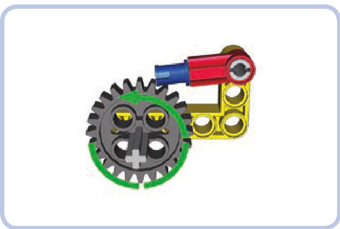
Figure 8-7: A simple pawl (red) securing a 24-tooth ratchet (grey). The ratchet is free to rotate counterclockwise, as indicated by the green arrow, but the moment it starts rotating clockwise, the pawl will lock itself against the nearest tooth (although it’s still possible to unlock it by hand).
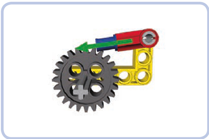
Figure 8-8: The angle of the pawl should be such that the line coming out of its mounting point aims slightly below the gear’s rim.
Figure 8-9: My working model of Leonardo da Vinci’s leaf spring catapult used a ratchet as a trigger, keeping the catapult loaded and firing it when unlocked. The ratchet was strong enough to store the energy of two bent axles acting as a spring.
The ratchet’s shape also matters a good deal—luckily, a simple pin is perfectly suited for our needs. The pawl also needs to be balanced so that its tip tends to drop on the gear under its weight. Ratchets, therefore, are gravity sensitive.
Not e It’s possible to create a gravity-independent ratchet by attaching an elastic element, such as a rubber band, that keeps the ratchet pressed down on the wheel just as gravity normally would.
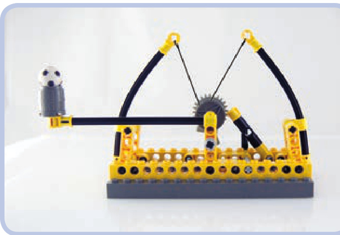
Figure 8-9 shows one possible use of a ratchet—as a means to store the potential energy of springs.
linear clutches
A linear clutch works just like the 24-tooth clutch gear described in Chapter 5—it slips under torque. By installing it between a motor and a mechanism, you can prevent the motor from stalling when the mechanism is blocked.
The difference between the linear clutch and the clutch gear is that the clutch gear needs to be meshed with a gear on another axle to work, whereas the linear clutch comes directly between two axles in single line. This saves a lot of space because the linear clutch can simply replace any axle that is at least 4 studs long. The linear clutch also fits between two universal joints that are at least 2 studs apart, and it doesn’t need to be supported, so it can work at any angle.
The linear clutch makes use of axle pins with friction. As Figure 8-10 shows, two of these are inserted into a pin joiner, and then their axle ends can be inserted into axle joiners or universal joints, which can be connected to axles of any length. Note that using this clutch for a prolonged period of time will eventually wear down its parts.
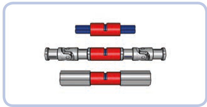
Figure 8-10: Two axle pins (blue) inserted into a pin joiner (red) are the core of the linear clutch (top). They can then be inserted between two axle joiners (middle) or two universal joints (bottom).
eccentric mechanisms
An eccentric mechanism, also called a crank mechanism, is used to transform rotary motion into reciprocating motion and vice versa. It’s a vital part of almost every car’s engine, transforming the linear movement of pistons into the rotation of the driveshaft.
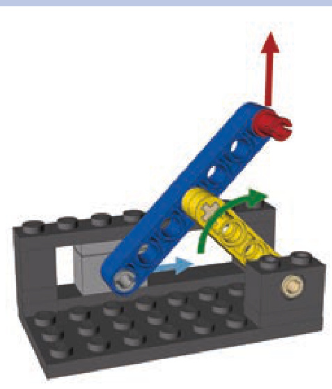
A typical eccentric mechanism consists of a disc and a short beam that connects the disc to a pushrod. As the disc rotates, the beam makes the pushrod move forward and backward along a straight line, as shown in Figure 8-11. Note that if the green pushrod is guided, it has only linear motion. In this case, it is guided by the yellow Technic brick.
The distance the pushrod travels depends on the disc’s diameter. The bigger the diameter, the longer the pushrod’s travel distance. We can also provide rotational motion using a shorter beam instead of a disc, as shown in Figure 8-12. Here, the distance the pushrod travels depends on the length of the shorter beam.
An eccentric mechanism can also be used to transform rotary motion into rocking motion (that is, partial rotary motion). This type of mechanism, shown in Figure 8-13, has no pushrod; instead, it has a second disc that performs a partial rotation back and forth. The range of its movement depends on the relationship between the two discs’ circumferences, and we can adjust the degree of movement by using different-sized discs. For this type of mechanism to work, however, the diameter of the second disc has to be larger than the diameter of the first disc, and the beam’s length has to be larger than the first disc’s diameter.
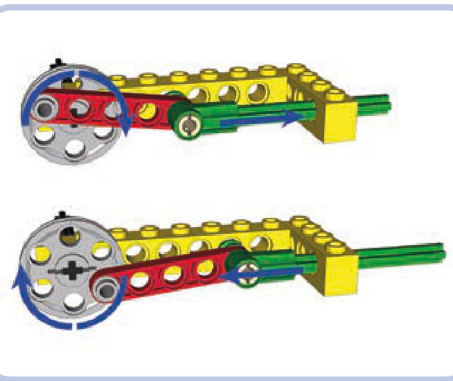
Figure 8-11: An eccentric mechanism with a disc (light grey), a beam (red), and a pushrod (green). The pushrod’s travel distance is equal to 2 studs— that is, the disc’s diameter minus 1 stud.
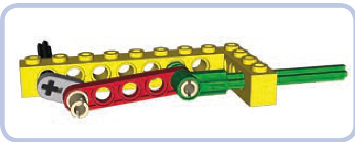
Figure 8-12: An eccentric mechanism with a shorter beam instead of a disc
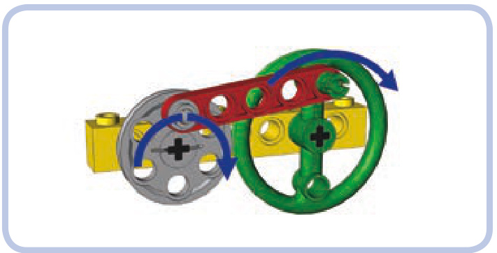
Figure 8-13: An eccentric mechanism with two discs connected by a beam. The smaller disc makes full rotations, and the larger disc makes only partial rotations back and forth.
As shown in Figure 8-14, we can also replace discs with beams in this type of eccentric mechanism. Because the second beam doesn’t make a full rotation, the whole mechanism takes up less space. Note that this type of mechanism works only in one direction; you cannot drive the grey beam with the green beam.
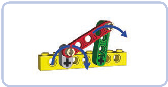
Figure 8-14: An eccentric mechanism with beams instead of discs. Because the second beam (green) makes only a partial rotation, the mechanism takes up less space.
Eccentric mechanisms can be put to a variety of uses, appearing in a car’s windshield wipers, an oscillating fan, and so forth.
Scotch yokes
A Scotch yoke is a simpler alternative to an eccentric mechanism. It does the same job—converting rotary motion into reciprocating motion and vice versa—while using a smaller number of moving parts. The parts, however, are less common than those in an eccentric mechanism. A Scotch yoke takes more space than an eccentric mechanism but is less likely to fail under high torque.
A Scotch yoke consists of a rectangular frame hung between two sections of an axle. The frame has a slot inside it into which a single pin located on a disc adjacent to the frame enters, as shown in Figure 8-15. As the disc rotates, the pin can go up and down freely inside the slot, but its sideways movement is translated directly to the frame and thus to the axles.
Each rotation of the disc makes the frame move forward and backward by a range equal to the disc’s diameter. The Scotch yoke’s range of movement is equal to the disc’s diameter, which means that it transforms the movement more efficiently than an eccentric mechanism would. We can increase the range by using a bigger disc and increasing the size of the slot inside the frame accordingly. The height of the slot has to be at least equal to the disc’s diameter, which also means that the yoke’s movement range is the minimum height of its slot.
Figure 8-15: Working cycle of the Scotch yoke with a frame (green) and a disc with a single pin (yellow)
a Scotch yoke
Oldham couplings
An Oldham coupling, also called an Oldham joint, is a coupling that transfers drive between an input and an output that are not aligned. While you can use universal joints or even gears to connect a misaligned output and input, these solutions may not always suit your needs. Using two universal joints tends to take a lot of horizontal space, and using gears may result in an unwanted change in torque and speed. An Oldham coupling maintains a 1:1 ratio and takes only a little space, though it is more complex, has a large diameter, and produces extra friction. To see an Oldham coupling in action, visit http://www.youtube.com/ watch?v=2M9cp_lJ4_I.
Oldham couplings consist of two identical attachments— one for the input and another for the output—and a single sliding element between them. In the real world, the major advantage of an Oldham coupling is how short it is; in the world of LEGO, we can make an Oldham coupling 3 studs long, which is still only half the space required by two universal joints.
an Oldham coupling
The coupling shown in Figure 8-16 can transfer drive between an input and an output that are misaligned by 1 stud horizontally and 1 stud vertically (the location of the input and output axles is shown in Figure 8-17). It is possible to build such a coupling using longer axles and thus increase the maximum displacement of its input and output. While the coupling will remain 3 studs long, however, its diameter will get significantly bigger.
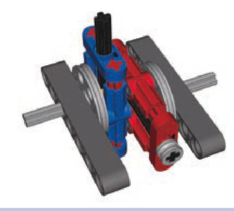
Figure 8-16: An Oldham coupling consists of two identical attachments (blue and red) and an element that slides between them. This Oldham coupling is only 3 studs long.
Figure 8-17: The maximum displacement between this Oldham coupling’s input and output is 1 stud horizontally and 1 stud vertically. The coupling can be expanded to allow greater displacement at the cost of increasing its diameter.
Schmidt couplings
A Schmidt coupling, like an an Oldham coupling, transfers drive between an input and an output that are not aligned while maintaining a 1:1 ratio between them. It, too, is an alternative to using gears or universal joints to transfer drive.
A Schmidt coupling consists of three discs or triangles, each connected with three links to one another, making six links total. The first disc is attached to the input, the third disc is attached to the output, and the middle disc doesn’t need any support—it can work while hanging in midair. Uniquely, this coupling’s input and output can move relative to each other because the middle disc equalizes their movement. The coupling can therefore transfer drive between two elements while they are in lateral motion, which is not possible with traditional gearing or Oldham couplings.
We can build a Schmidt coupling with LEGO pieces by using piece #57585 as a base for the triangles, as shown in Figure 8-18 (note that only pins without friction should be used). The coupling is 5 studs long, but it’s extremely robust and can handle greater torque than any alternative solution, including universal joints. It’s also mesmerizing to watch. The coupling shown in Figure 8-19 can be moved by up to 5 studs, and we can increase this value by making the triangles’ arms longer. The links should be made longer accordingly—however, for the coupling to work, each link (shown in yellow) can be only a little longer than the radius of the triangle.
Figure 8-18: LEGO piece #57585 (light grey) can be used to create triangles of various sizes.
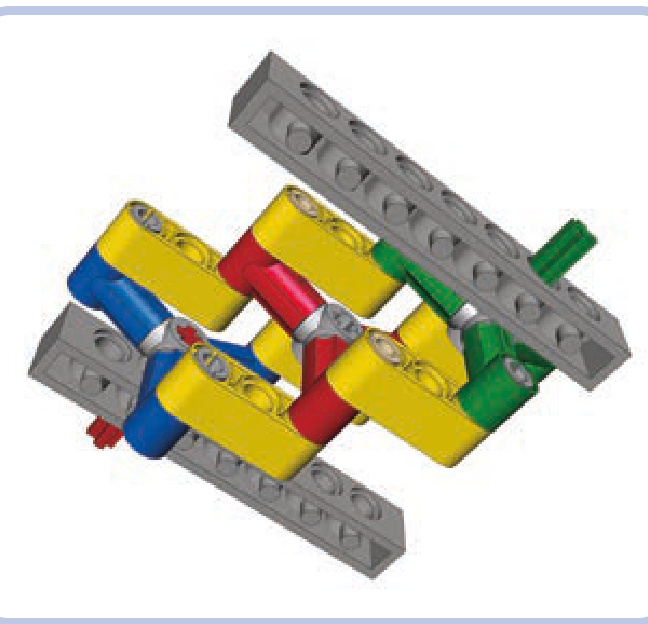
Figure 8-19: A Schmidt coupling with three triangles (in green, red, and blue) and six links (yellow). Note that the middle triangle (red) doesn’t need any support—it can even move as the coupling works.
stepper motors
In the real world, stepper motors rotate by a constant angle every time they are turned on instead of rotating continuously. For example, we might have a stepper motor that
performs one-quarter of a rotation every time its button is pressed. Such motors are very useful for complex automations of many sorts; real assembly lines are full of stepper motors.
While LEGO does not produce this kind of motor, we can build a custom one mechanically. By adding a simple mechanism to a motor, we can make it work like a stepper motor and use it for a variety of tasks; for example, we can control a sequential gearbox remotely.
To create a stepper motor, we need a knob wheel mounted on a motor’s output axle and a beam fastened to that wheel with an elastic element, such as a shock absorber or a rubber band, as shown in Figure 8-20.
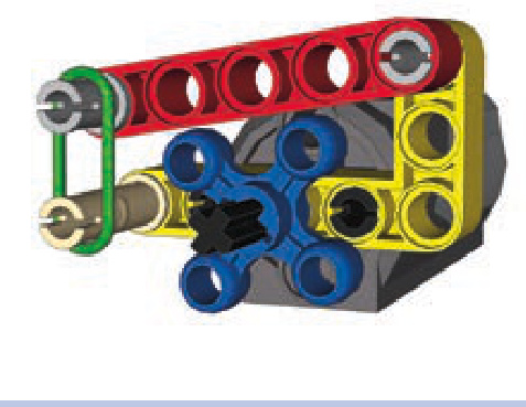
Figure 8-20: The knob on the motor’s output axle (blue) has a beam (red) fastened to it at all times by a rubber band (green). This makes a regular motor behave similarly to a stepper motor.
By keeping the beam fastened to the knob at all times, we slow the motor down every quarter rotation (90 degrees). The motor takes a while to overcome the pressure and perform another quarter rotation; its constant rotary movement now becomes intermittent. By turning the motor on for just the right amount of time, we can control it precisely, making it turn by a desired number of rotations. To keep track of the number of rotations, we can watch the knob or simply listen to the sound of the motor, which is quite different from a motor running continuously. Note that this mechanism exerts some pressure on the motor, causing the motor’s internal parts to wear down faster than usual.
Geneva mechanisms
A Geneva mechanism (see Figure 8-21), sometimes called a Geneva drive or Maltese cross mechanism, converts motion between its input and output so that every rotation of the input advances the output by a specific, constant angle. In plain English, that means it converts continuous rotary motion into intermittent rotary motion. A Geneva mechanism may appear odd, but it’s quite common. For example, Geneva mechanisms appear in mechanical watches and movie projectors, where they stop every frame of the film for a fraction of a second.
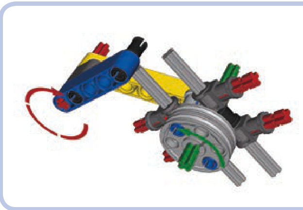
Figure 8-21: A simple Geneva mechanism with an input (red) and an out put (green). Each rotation of the input advances the output by a quarter rotation—that is, 90 degrees.
Building a Geneva mechanism with LEGO pieces is a tough job since real Geneva mechanisms use complex circular elements to achieve the desired motion. The following BI shows a relatively simple and small model.
Note that the output of this mechanism can rotate freely when not engaged by the input, while in a real Geneva mechanism, the output remains locked when not engaged by the input. Building a model with LEGO mechanisms in which the output remains locked like this is extremely difficult, and any attempts to do so will result in very large and complex mechanisms. The Geneva mechanism can be simulated in a simple way, though, by putting lots of friction on the green axle. This friction makes the mechanism stop unless engaged by the input.
a Geneva mechanism
reverse lights
Let’s assume we have a vehicle on which we want reverse lights that turn on and off automatically when the vehicle backs up. We can create such lighting with a single switch connected to a driveshaft; we just have to block that switch to limit it to the on and off positions only. The Power Functions switch has an on-off-on switching pattern, and by blocking one of its extreme positions, we can limit it to on-off, as shown in Figure 8-22.
With the switch blocked, all we have to do is connect the axle that goes through it to the driveshaft, using a gear with a clutch so that the switch won’t stop the driveshaft once switched, as shown in Figure 8-23. Note that the gear ratio matters here: Any gear reduction from the driveshaft will slow down the switching, and we don’t want that. For the switch to react to changes in the driveshaft’s direction quickly, we need a 1:1 gear ratio or higher.
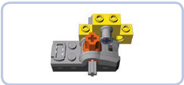
Figure 8-22: In this simple way to limit a Power Functions switch to the on and off positions, the pin prevents the orange switch from moving to the far right on position).
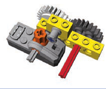
Figure 8-23: A blocked Power Functions switch is connected to a vehicle’s driveshaft (red) through a 24-tooth gear with clutch (white).
Any lights connected to the switch in this setup will turn on when the vehicle drives in one direction and off when it drives in another. There’s a chance we will get the directions wrong and our reverse lights will turn on when the vehicle goes forward; to fix this, simply change the direction the axle inside the switch rotates by moving the switch to the opposite side of the driveshaft or by adding one more gear between it and the driveshaft. Of course, this mechanism adds the friction of the clutch to the driving system of the gear while the vehicle is moving. This friction causes a loss of power in the drivetrain, which gets bigger with higher driveshaft-to-switch gear ratios.
flashing lights
When we want LEGO lights to flash, we have two options: We can use old 9V bricks with lights (shown in Figure 8-24), which have the built-in ability to flash, or we can use LEGO LEDs from the Power Functions system, which require adding a custom mechanism.
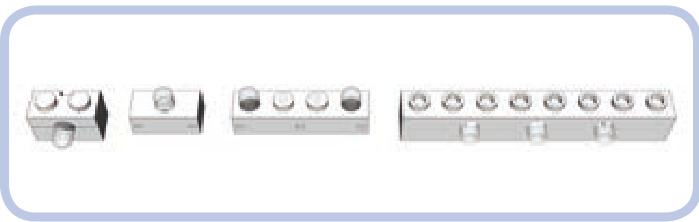
Figure 8-24 Four types of 9V bricks with lights
Depending on the polarity of the power supply, 9V bricks with lights are programmed to provide steady light or to flash. To switch between the two modes, change the orientation of one of the plugs of the wire connecting the brick to the power supply—or, more simply, rotate the brick on the plug 180 degrees, as shown in Figure 8-25.
Bricks with lights, however, have a number of dis advantages when compared to LEGO LEDs. Most importantly, they are long out of production, so it’s difficult and expensive to find a brick in good working condition today. Secondly, they use tiny incandescent light bulbs, which means that they consume a lot power, are prone to failure, and produce a strong yellowish light in all directions, as shown in Figure 8-26. LEGO LEDs are free from all these disadvantages, and they fit in much smaller spaces. Their only drawback is the lack of a built-in ability to flash, which we can add mechanically.
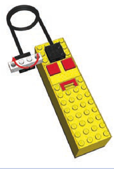
Figure 8-25: A -stud 9V brick with lights connected to a 9V battery box. By rotating the brick on the plug 180 degrees, we can switch between its lighting modes.
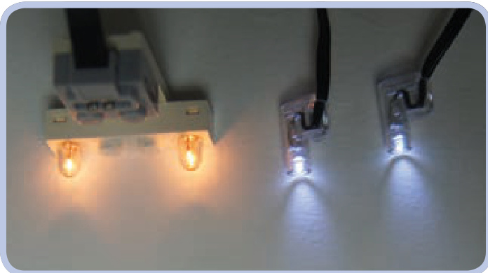
Figure 8-26: A 1×4-stud 9V brick with lights (left) and a pair of Power Functions LED lights (right). Note the difference in the color and direction of the light.
To make LEGO LEDs flash, we need a switch and a motor. Using an old 9V switch is the easy way, but we can use a Power Functions switch as well, which we can connect via an eccentric mechanism. Figures 8-27 and 8-28 show both versions.
With the old 9V switch, adding the ability to flash is simple: The switch can be connected directly to a motor whose rotary motion will keep turning it on and off, thus making the lights connected to the switch flash. The flashing frequency can be adjusted by adding a gear between the
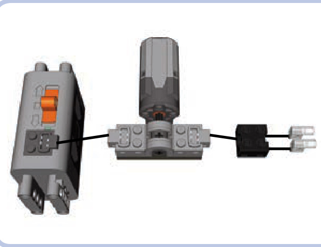
Figure 8-27: The old 9V switch
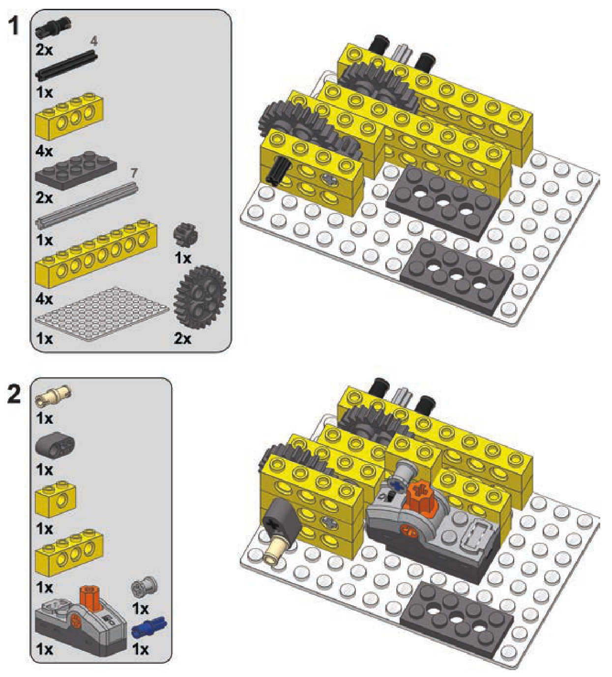
To create turn signals, we need to extend our flashinglight mechanism by connecting two more switches to it. The resulting device will be controlled by a single motor and will have two groups of LEDs connected to it; one will flash or the other will, depending on the motor’s direction.
Since we discussed how to make a flashing-light mech anism in the previous section, let’s focus on the two extra switches. We need to hard-couple them so that turning one switch on turns the other off. The coupling can be done with two gears, preferably two 16-tooth gears (as shown on the left in Figure 8-29), because they are the smallest gears accurate enough, or two half bushes with teeth (as shown on the right in Figure 8-29). The important thing is to keep the two axles going through the two switches at slightly different angles so both switches can’t be turned on or off at the same time.
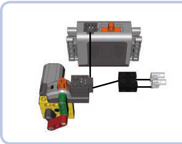
Figure 8-28: The Power Functions switch
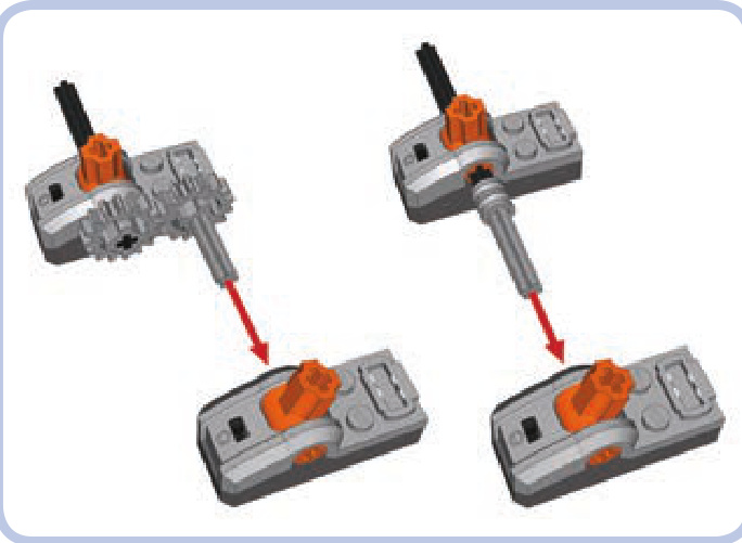
Figure 8-29: Hard-coupling two Power Functions switches with gears (left) and toothed half bushes (right). Note that the angle of axles coupled this way differs, preventing the two switches from being turned on or off simultaneously.
motor and the switch or by changing the motor’s speed. Note that Power Functions extension/adapter wires are needed to use the old 9V switch with Power Functions LEDs and power supplies. The old 9V power supply requires no adapter.
The Power Functions switch needs to be motorized through an eccentric mechanism to make the lights connected to it flash. The eccentric mechanism keeps the switch going back and forth through its three positions (on-off-on).
turn signals
Next, with the two switches hard-coupled at different angles, we need to block one of them in the same way as with the reverse lights described earlier in this chapter (see Figure 8-30). We will limit the switching pattern from onoff-on to on-off. Since the switches are hard-coupled, both will be blocked.
Now that we’ve covered how to make LEGO lights flash, we can take this knowledge one step further and create turn signals for our vehicle.
Now we have to connect the axle of one of the switches to the input of the flashing-light mechanism. A gear with a clutch is needed to allow the input to keep running after the switches are switched, as shown in Figures 8-31 and 8-32.
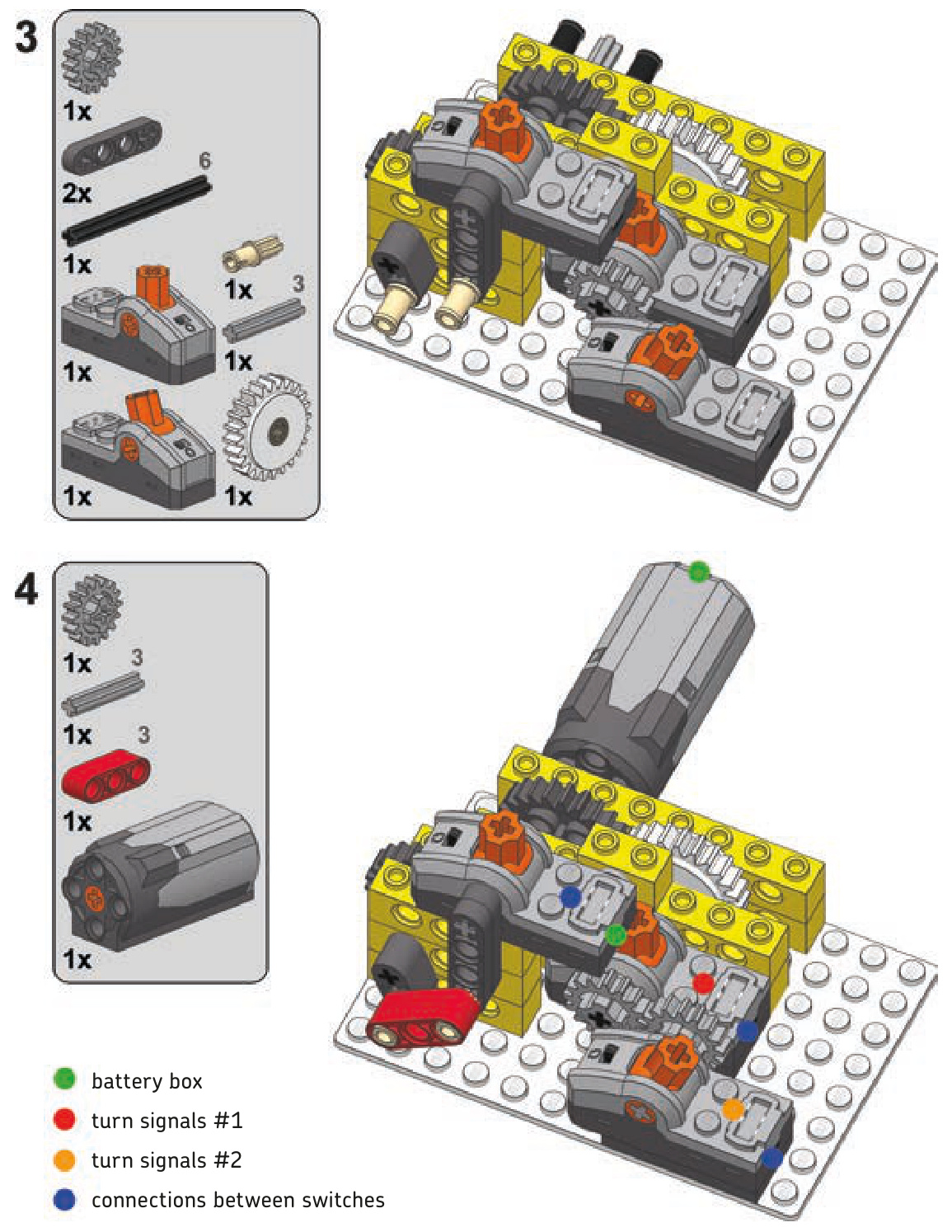
The only thing left to do at this point is to connect all these elements electrically. A connection scheme for the variant with the 9V switch is shown in Figure 8-33. The variant with the Power Functions switch follows the same pattern: The master switch (the one used in the flashinglight mechanism) is connected to the same power source/ control module as the motor. The two child switches (the hard-coupled ones) are connected to the master switch and have lights connected to them. Thus, as the master switch creates a flashing effect, the child switches control which
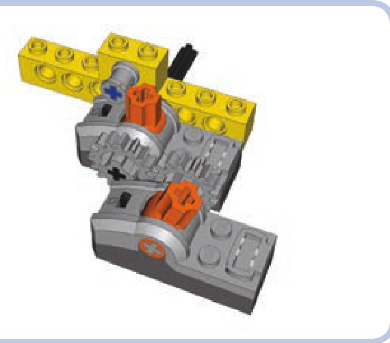
Figure 8-30: Two hard-coupled switches with one of them blocked. The hard-coupling makes the block work on both switches.
Figure 8-32: A more complex variant uses the Power Functions switch and an eccentric mechanism to make lights flash. The gear is identical to that of the previous figure.
Figure 8-31: Two hard-coupled switches connected to a motorized flashinglight mechanism that uses an old 9V switch. Note the gear down between the motor and the 9V switch—it lowers the flashing rate of the lights to a realistic value.
Figure 8-33: Electric connection scheme for the simpler mechanism variant. For a remote-controlled model, you should connect the master switch to the same IR receiver as the motor.
group of lights is flashing at the moment. You can switch between the two groups by changing the motor’s direction.
Note that there is no limit to the number of flashing lights we can control with this method. And the same motor that controls this mechanism can be used to steer the vehicle that houses it, making the turn signals work automatically as you steer your model!
complex turn signals
double-axle turntable transmission
Transmitting drive through a Technic turntable is quite easy with just one axle—we just have to put the axle through the turntable’s center. However, one axle is not enough for some vehicles. Tracked excavators, for instance, need two separate axles to drive the right and left tracks, and their propulsion motors are often located in the superstructure, which is separated from the chassis by a turntable. In such a case, we can use a transmission driving ring (as shown in Figure 8-34) or an empty differential housing (as shown in Figure 8-35).
The disadvantage of such a transmission system, other than its complexity level, is that when the superstructure rotates relative to the chassis, one of the axles is affected by its movement: the blue one in Figures 8-34 and 8-35. The axle is actually driven by the superstructure’s movement, causing the whole chassis to turn. However, as the superstructure’s rotation is usually slow, the effect is negligible, and it can be further minimized by gearing down both axles below the turntable. The advantage is that this transmission system allows you to build a tracked vehicle with all the electric elements in the superstructure. This means that no wires go through the turntable, which enables the superstructure to rotate any number of times without the risk of damaging any elements going through it.
Both variants can be built in a similar way. However, as the transmission driving ring variant is more practical, we will focus on it. The building instructions for this variant are shown next. Notice that the chassis and the superstructure can be easily built around this variant.
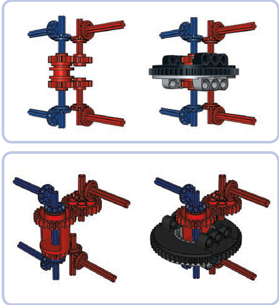
Figure 8-34: Scheme for transmitting drive through a turntable for two axles independently. Elements transmitting the drive are marked red and blue to show their independence. This variant uses a transmission driving ring to transmit drive over the blue axle that goes through the turntable’s center. Note that there is no axle joiner inside the driving ring, so it rotates freely on the axle.
Figure 8-35: The same transmission system with an empty differential housing instead of a transmission driving ring. This variant is simpler but less practical because of the large 24-tooth gear on the housing.
a double-axle turntable transmission
a sturdy universal joint
While ready-made LEGO universal joints have a number of advantages, they are prone to failure when subjected to high torque. We can build a custom universal joint out of basic pieces that will act the same while being more robust, at the cost of bigger size (shown in Figure 8-36).
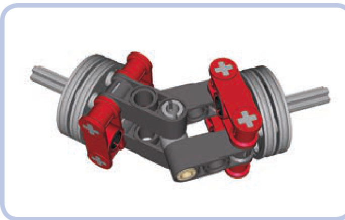
Figure 8-36: A custom universal joint is more robust but also larger than ready-made ones.
a universal joint

the LEGO pneumatic system
The LEGO pneumatic system is a miniature model of reallife pneumatic and hydraulic systems. It consists of three basic modules: a pressure generator, such as a manual pump or a motorized compressor; a control module, one or more valves that direct the flow of air; and cylinders, which convert pressure to linear movement. The modules are connected by elastic pneumatic hoses.
The basic working principle of a pneumatic system is based on the tendency of air to move from areas of high pressure to areas of low pressure. The pressure generator fills the pneumatic system with pressurized air, and then the air is directed to the cylinders using the control module, which makes the cylinders extend or retract. When the pressure of the system is equalized, all movement stops.
Every pneumatic system has limited capacity for air pressure. In the case of LEGO models, that limit is normally three bars, which is roughly equivalent to three times atmospheric pressure. If a LEGO pressure generator exceeds this capacity, the pneumatic hoses may pop off the ports of pneumatic pieces.
Because the LEGO pneumatic system relies on hoses and connectors, it is not perfectly closed and is subject to microleaks. Microleaks, small amounts of air leaking out of the pneumatic system, usually occur at the ends of pneumatic hoses (or in the middle if they are damaged). These microleaks result in reduced efficiency. And of course, as with any mechanical system, complexity is the enemy of efficiency in pneumatics.
Not e Although LEGO connectors in the pneumatic system are technically called inlets and outlets, I’ll call them ports for the sake of simplicity.
There are actually two different LEGO pneumatic systems: Old and New. Each works a bit differently, as described in the next sections.
the Old system
Introduced in 1984, the Old LEGO pneumatic system (shown in Figure 9-1) is relatively complex. Its control module includes two interconnected pieces and one pneumatic hose that connects the pressure generator to the cylinders. Although the last LEGO set that included the Old system was released in 1987, this durable system continues to be widely available.
The pump shown in red at usually has a spring. When pushed, it pumps the surrounding air through its port, and the spring returns the pump to its initial rest position when released.
Figure 9-1: The Old-style pneumatic system uses two blocks to control airflow. The grey lines in this diagram represent hoses.
The light-grey element at is a distribution block, which includes a special one-way valve. Air is delivered from the pump into the distribution block’s middle port, and the one-way valve forces the two side ports to pump air in only one direction: The port on the left takes air in, and port on the right expels the air. Thanks to the distribution block, we can not only increase the pressure in the LEGO pneumatic system but also decrease it by expelling air from the system.
The light-grey element at is a valve, which is connected to the distribution block by two hoses. A single distribution block can be connected to many valves using forked hoses. The total number of valves depends on how many pneumatic cylinders are meant to be controlled independently.
The valve has a lever that can be switched to one of three positions. One position extends all connected cylinders, another retracts the cylinders, and the third (middle) position cuts the connection that goes through the valve, effectively locking all cylinders. This third position is called neutral, and it is needed when you have many valves in a system because it prevents the valves from interfering with each other. Additionally, with the valve in neutral, the pressurized air remains sealed and thus can be used more efficiently in other parts of the system.
The yellow element at is a cylinder, which extends when air is delivered to it and retracts when air is sucked from it.
Not e When a cylinder is subjected to suction, the air pressure inside it drops until it becomes lower than the atmospheric pressure surrounding it (one bar), at which point the cylinder starts to retract. For this reason, the LEGO pneumatic system can exert up to three bars of pressure for extension, but only up to one bar of pressure for retraction.
Compared with the New pneumatic system (discussed below) the Old pneumatic system does offer one advantage: It requires only one hose to connect a cylinder to a valve. But it also has several disadvantages. One is that it applies much less force to retract a cylinder than it does to extend it because air is expelled from the cylinder during extension and drawn in during retraction. Since the force exerted by the cylinders in a pneumatic system depends on whether they extend or retract, this is often considered a significant disadvantage, and this disadvantage is one of the main reasons why the New system was created.
Also, the control module in the Old system is complex, requiring two hoses for every valve connected to the distri bution block. Finally, the Old system has many unique pieces (the pump, distribution block, and cylinders) that haven’t been produced since 1987, making it virtually obsolete.
the New system
LEGO introduced the New pneumatic system (shown in Figure 9-2) in 1989 with the goal of simplicity and effi ciency. The New system eliminated the distribution block and redesigned the pumps and cylinders, though it does use the Old valves. This new system is much more like real pneumatic and hydraulic systems.
Figure 9-2: The New pneumatic system uses a simple design.
The yellow element at in Figure 9-2 is a pump that works only with the New system. The light-grey valve at is the same as that in the Old system except that it is connected a bit differently: Air is delivered into it through the middle port, and its side ports are connected to the cylinder. Either valve’s port can be connected to either cylinder’s port; this connection determines which of the valve’s two extreme positions makes the cylinder extend or retract.
The yellow element at is a cylinder. It extends or retracts depending on which port the air is delivered to.
Unlike the Old system, the New one expels air through the valves, resulting in distinctive hissing sounds when valves are switched under high pressure. Also, because the New system doesn’t use suction, retraction is only slightly weaker than extension.
Not e You can swap the cylinders between the Old and New systems, but the cylinders from the Old system will perform poorly due to their different internal construction.
Compared with the Old system, the New system offers the advantage of using a simple control module, and the same force is exerted by the cylinders regardless of whether they extend or retract. Its main drawback is that two hoses are required for every cylinder connected to the valve, which can make multicylinder pneumatic systems very complex.
The New pneumatic system is used by most LEGO builders today, though some choose the Old system in order to reduce the number of hoses needed to connect cylinders or simply because they prefer the red cylinders.
Although the principles of the New system haven’t changed since 1989, some new pieces have been added and existing pieces have been updated.
an inventory of pneumatic parts
This section describes all existing pneumatic pieces, in order of function, from pressure generators, control modules, and cylinders to miscellaneous pieces. Since most of the pieces in the New and Old systems are interchangeable, I’ve listed them together.
pneumatic pump (Old)
This is a large manual pump with a single port and a springloaded rod. It comes in two lengths and in both red and yellow. It draws air in from the outside when the rod is pushed; when the rod is released, the spring returns the pump to its initial, neutral position.
The pump’s bottom can be mounted on studs, and both its ends have regular Technic holes. The lower end (the one with the port) is 2 studs wide, and the upper end is 1 stud wide. The pump’s upper end makes manual pumping uncomfortable: When pumping fast for a prolonged time, it quickly becomes hot due to the compression of the air inside it.
pneumatic pump (New)
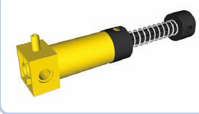
This is the large manual pump from the New system. This part is always yellow in LEGO Technic sets and transparent light blue in LEGO Education sets.
Like the Old system’s pump, it contains one port and a spring-loaded rod. It works just as the old pump does, and its dimensions are almost identical, except for the addition of a contact pad on its upper end. This contact pad is designed to make manual pumping much more comfortable, and it does, but the pump is still prone to heating up just like the Old one.
small pneumatic pump (New)
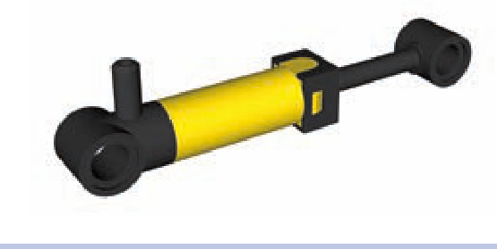
This small pump with one port has a rod that extends by 2 studs and no spring. It is best used with motorized compressors rather than manual pumps. Because it’s so much smaller than the other pumps, it takes longer to provide comparable pressure, which is why compressors often include more than one such pump. It is also much less prone to heating.
This pump comes in yellow, blue, and a transparent light blue. In 2011, a new version was released with the 8110 set; it’s light grey and is half a stud longer, resulting in slightly increased capacity.
distribution block (Old)
hasn’t been produced since 1987. It has three ports on one side, and air is delivered to the middle one. A one-way valve inside affects how the ports work: The middle port allows air to flow both ways, the left allows air to flow in only, and the right allows air to flow out. If you use the ports incorrectly, the valve will close, stopping all air circulation inside the block. The valve will reopen once you connect the ports properly.
valve with studs
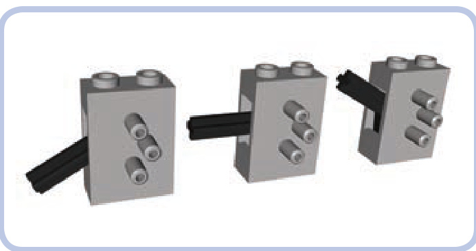
The valve is the size of two bricks and a plate stacked, and it is always light grey. It has three ports on one side, with air delivered to the middle one.
A lever (roughly 1.5 studs long) on one of the valve’s narrow sides can be switched to one of three positions. The middle position, called neutral, cuts the connection inside the valve, effectively disconnecting the side ports from the rest of the pneumatic system. The top and bottom positions control the flow of air through the valve’s side ports, as shown in Figure 9-3, making cylinders connected to these ports extend or retract. (The valve does not actively take in air; it only receives air through its ports and expels it through the hole that houses the switch.)
The distribution block is a light grey piece that’s the same size as a LEGO brick. It is used exclusively in the Old pneumatic system for sucking air out of the cylinders and
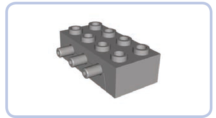
Figure 9-3: The direction of airflow through the valve’s ports: Blue arrows show air coming from the pump, green indicates air coming out from the valve to the cylinder, and red indicates air returning from the cylinder to the valve.
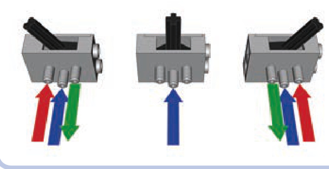
A valve can be attached on the top or bottom of any studded LEGO piece. It can also be mounted between two Technic bricks, which can then be connected with pins to any piece that has at least five pin holes (see Figure 9-4).
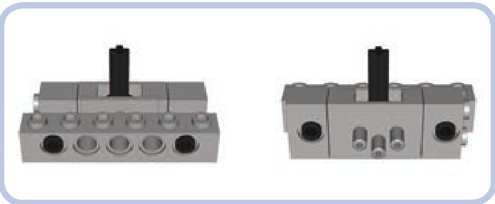
Figure 9-4: By placing a Technic brick on each end of the valve (front and back shown), you can connect the valve to a brick or beam that is at least five pin holes long.
valve with no studs (New)
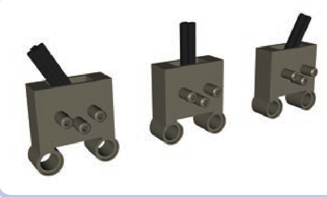
Introduced in 2003, this New valve works the same as the valve with studs. Unlike the Old valve, it comes in dark grey, but it has similar dimensions. Aside from the color, the only difference is its lack of studs and the addition of two pin holes, 1 stud apart, at one side of the valve. These changes make it better suited for studless constructions. Also, because the valve’s points of attachment are on one side and the valve’s lever is on the other, the lever remains conveniently exposed when the valve is attached to something.
large cylinder (Old)
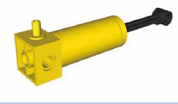
This cylinder from the Old system, which hasn’t been produced since 1987. It includes a single port and a plastic rod that extends by nearly 4 studs. Available in yellow and red, its dimensions are the same as those of the Old large pump. Unlike the Old pump, however, it has no spring. The cylinder’s upper part expels air when extending and draws it in from the outside when retracting, and the cylinder exerts more force when extending than it does when retracting. It’s only partially useful with the New pneumatic system because it can be extended but not retracted.
6L cylinder (Old)
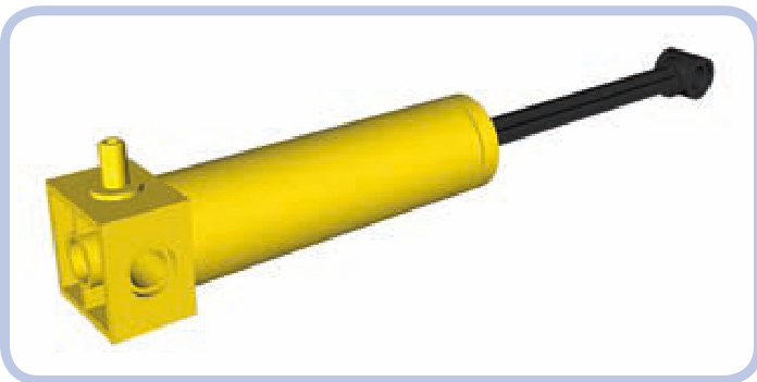
This yellow cylinder is basically just a longer version of the Old system’s large cylinder. It has a single port and a plastic rod that extends 6 studs, and it has no counterpart in the New pneumatic system; in fact, it is the only pneumatic cylinder this long. Its plastic rod and long reach make it more likely to break under stress than any other cylinder.
As with all Old-style cylinders, its upper part expels air when extending and draws it from the outside when retracting, and it exerts more force when extending than when retracting. And, just as with the regular large cylinder, its usefulness in the New system is limited because the New system doesn’t allow it to retract.
small cylinder (New)
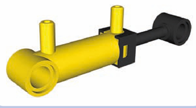
The New system’s small cylinder has two ports and a plastic rod extending 2 studs. In the Technic sets, it’s always yellow, though it comes in a transparent light blue in the Education sets.
This rare and expensive pneumatic piece is easily confused with the small pneumatic pump. This piece is unable to exert large force due to its small capacity, but it’s valued for its small size. As with all cylinders in the New system, it is completely airtight.
large cylinder with square base (New)
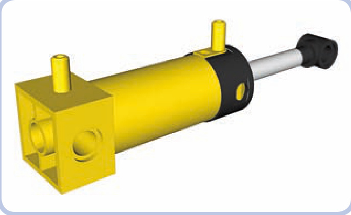
The New system’s large cylinder is one of the most common pneumatic pieces. It has two ports and a metal rod extending by nearly 4 studs that makes it very robust. It is similar in size to the large pneumatic pump.
large cylinder with round base (New)
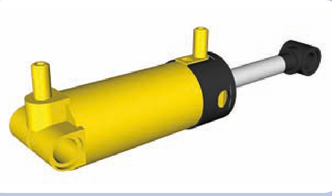
This updated version of the large cylinder, introduced in 2002, has two ports and a metal rod extending by nearly 4 studs. The only difference between this cylinder and the Old one is that it has a round rather than a square base; the round base takes up less space and cannot be mounted on studs. However, the rounded design allows the New cylinder to tilt in tight spaces, which has made it very popular.
The square, Old version of this pump requires a large margin of free space around its lower end in order for the cylinder to tilt, which makes it less realistic. Real hydraulic cylinders are almost always mounted on a pin joint so that they can pivot during their stroke, which prevents loads from bending the actuator. The round base on the New cylinder allows for this type of action, making it more realistic than the square version.
pneumatic tubes and hoses
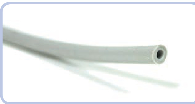
The thick elastic rubber hose is a vital part of the Technic pneumatic system. It comes in various lengths and colors—black, grey, and blue—and is easy to insert through Technic holes and connect to ports of the pneumatic system.
When working with hose, remember that LEGO pneumatic systems cannot maintain high air pressure for prolonged periods and each hose leaks somewhat, so the system becomes increasingly inefficient with each hose you add. Additionally, hoses tend to pop off ports when the pressure exceeds three bars, and if a hose is stretched or damaged, it can pop off even below three bars. The oldest hoses, rarely found today, were made of a material that slowly broke down when exposed to UV light, causing them to develop cracks and leaks. The newer hoses are made of silicone and are mostly immune to these problems.
The 4 mm hoses make it easy to circulate air through any pneumatic system, no matter how complex, and they take up very little space in LEGO constructions. Their flexibility and resilience allows them to span components that need to have relative motion, but their inner ducts are narrow and can easily become blocked. To avoid blocking the tubes, be sure that the surrounding structures do not press on a hose and that no hose is stretched or bent sharply.
Figure 9-5 shows a pneumatic hose connected to the upper port of a (New) large cylinder. Note that when a hose is attached to a port, it becomes thicker than 1 stud. As a result, the part of the hose with the port inside it can’t fit through a Technic hole.
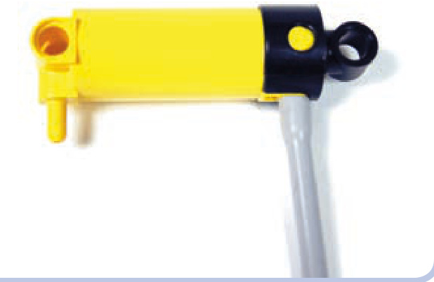
Figure 9-5: A hose connected to a cylinder port
In addition to ports, pneumatic hoses can also be connected to thick rigid tubes in order to join several pneumatic hoses to create longer ones.
In real hydraulic and pneumatic systems, hose is always used to describe a flexible part, and tube is used to describe a rigid part. In keeping with this terminology, I’ll refer to the flexible silicone parts as hoses and the rigid parts as tubes. Figure 9-6 shows how a tube can connect two pneumatic hoses. But these tubes can also be connected to any studded structure, such as a brick, in a way that would not be possible with the regular pneumatic hose.
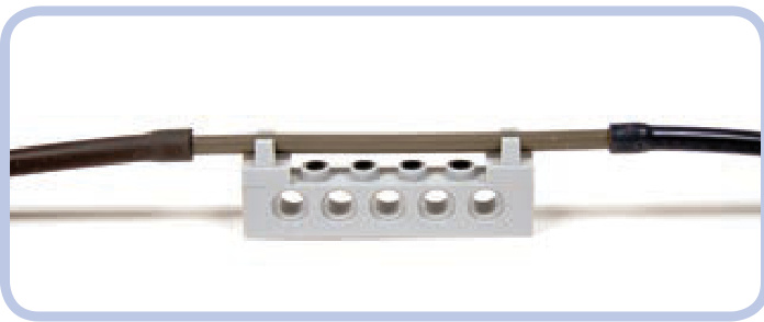
Figure 9-6: A tube connecting two hoses, connected to a Technic brick by two tiles with clips
Not e Real machines equipped with pneumatic or hydraulic systems often use rigid tubes to traverse structures that do not bend, such as the boom of a crane. The tube makes this type of construction easy to model with LEGO pieces.
T-piece (Old)
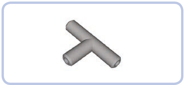
The Old version of the T-piece, which hasn’t been produced since 1996, is simply a small, T-shaped piece with three ports. When air is forced into one port, it flows into the two other ports, making the T-piece work as a pneumatic parallel connector.
T-pieces are used to divide pneumatic hoses in two by connecting a hose to each port (see Figure 9-7). Two of the hoses act as a single section with the T-piece in the middle, and the third one acts as its branch. Because every T-piece adds one new branch to a pneumatic hose, in order to split a hose into four, you need three T-pieces: one to split the hose in two, and two more to split each of the two resulting hoses into two again. The rule is a universal one: splitting a single hose into hoses requires (n – 1) T-pieces.
Figure 9-7: Two T-pieces allow a single hose (blue) to branch into three individual hoses (red).
Not e Splitting hoses lowers the effectiveness of the whole pneumatic system because changing the direction of airflow by 90 degrees produces drag.
T-piece (New)
The updated version of the T-piece has a ball-shaped center, which makes it easier to disconnect from hoses. It works the same as the Old T-piece, but it is stronger and slightly more effective in reducing drag. T-pieces are always light grey.
hose connector with an axle joint (New)
This piece was introduced with the 8110 set in 2011. It looks a bit like the T-piece, but instead of splitting hoses, it’s used to extend them.
Designed to connect two sections of pneumatic hose in a way that makes the hoses easy to remove, this piece allows you to easily connect or disconnect two pneumatic systems. Due to its design, this piece is especially handy for creating pneumatic power take-off (PTO), a connection that powers external attachments like a pneumatic snowplow or a knuckleboom crane, as in the original 8110 set. Many agricultural machines also come with PTOs; for example, a tractor might swap between different attachments.
cylinder bracket
The new pneumatic system doesn’t include 6L cylinders, and the regular large cylinders, which have nearly 4 studs of extension range, are too short for certain purposes. The solution is to join two cylinders with the bracket shown in Figure 9-8 so that they work like one cylinder with rods extending from both ends, effectively doubling both the length and extension range.
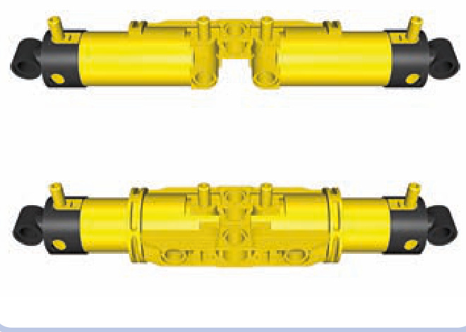
Figure 9-8: It takes two brackets to secure two cylinders.
The brackets are symmetrical, so you can have one cylinder with ports facing up and the other with ports facing down, but having all ports on one side will make it easier to connect hoses.
Not e For the cylinders to work as one, you have to couple their lower and upper ports separately with hoses forked using T-pieces.
Figure 9-9 shows two brackets secured around two cylinders by two axles and two 3L beams with pins. The brackets are not physically attached to the cylinders or to each other. To attach them, either insert axles through their axle holes or add pins to their central holes and connect them with 3L beams. The pins-and-beams method is more reliable because it prevents the brackets from coming apart; however, it uses the brackets’ central holes, which are often better used for routing hoses.
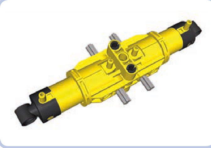
Figure 9-9: Two brackets secured around two cylinders
The airtank stores compressed air. This part is blue in Technic and white in the Education system. It comes in handy particularly when you want to create a pneumatic system that doesn’t require constant pumping. While with a little tinkering you can connect pneumatic hoses to plastic bottles or bags to store air, the airtank is the only original LEGO piece designed for this purpose.
Not e Each pneumatic system has a capacity equal to the volume that can be filled with pressurized air. This volume is typically related to hoses: Adding several long hoses adds to the capacity significantly. The airtank’s capacity, however, is far greater than that of any number of hoses.
To have the air stored in the airtank available for the whole pneumatic system, place the airtank between the pressure supply and the control module.
According to LEGO, it takes 30 to 35 repetitions with a large pneumatic pump to fill the airtank completely. At roughly 40 repetitions, the pressure will reach the critical three bars, causing either the pump to stop working or the hoses to pop off its ports. (If a breach occurs, the pressurized air will escape the airtank in a split second.)
Figure 9-10: Because of the shape of the airtank’s bottom, a spacing of at least a single plate is required to connect it to anything larger than a - stud area. A plate is used here. Note that despite the presence of the large red plate, it’s still possible to connect hoses to this airtank, thanks to its angled ports.
Despite its apparent simplicity, the airtank’s shape is actually quite complex. Its bottom has a connecting area that can be used with any bricks or plates. To attach it to anything larger than a piece, try adding a plate as a buffer (see Figure 9-10).
The airtank’s connecting area also includes three 1-stud-deep axle holes, which you can use to mount the airtank on axles or axle pins. You can do the same with the single axle hole above each of the airtank’s ports.
manometer
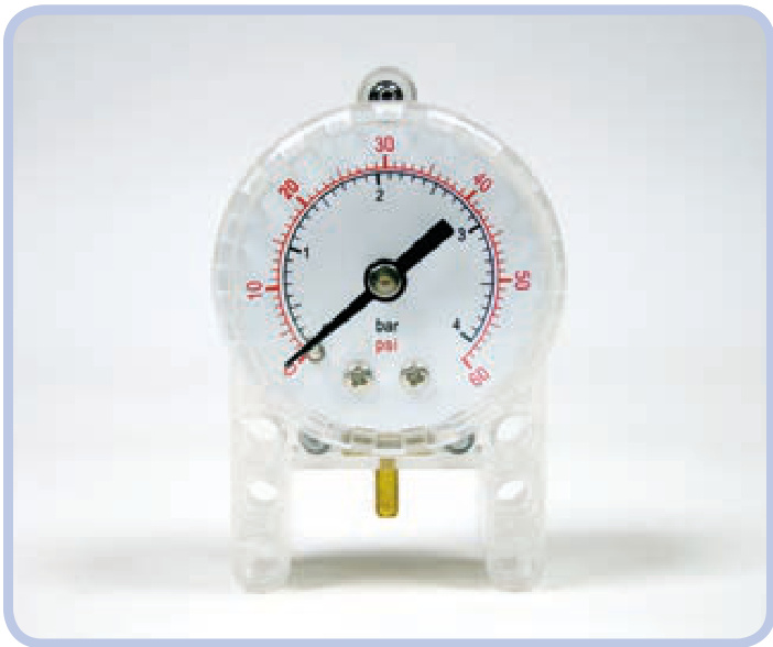
The manometer was released in 2008. It is designed to measure the air pressure in a pneumatic system in both pounds per square inch (psi) and bar units. It is enclosed in a semitransparent case, with a single metal port at the bottom.
To use the manometer to measure air pressure in the pneumatic system, place it between the pressure supply and the control module. It can be connected with a single section of pneumatic hose to practically anything, whether that’s the airtank or any two sections of a hose using the T-piece. Figure 9-11 shows two examples of manometer placement.
The manometer’s usefulness is limited. If you choose to use it, remember that it is best used with the airtank. If you choose to use the manometer on a pneumatic system without an airtank, its readings will change drastically with each movement of a pump or valve.
modding the pneumatic system
The pneumatic system is ripe for experimentation. Here are some common ways to tinker with it.
non-LEGO hoses
It’s easy to replace the original LEGO pneumatic hoses with custom ones, as long as the custom hose is elastic and thick (if you want to be able to insert it through Technic holes) and as long as it has reasonably large inner ducts. Some industrial hoses may come in handy for this purpose—for example, the fuel hoses used for radio-controlled models. Medical drip hoses—that is, IV lines—can be used too, but they tend to be sticky and to collect massive amounts of dust.
non-LEGO airtanks
Although the LEGO airtank is quite useful, you can replace it with practically any airtight container. Plastic bottles or bags and even balloons can work very well as long as you connect them to the pneumatic system in a way that keeps them airtight.
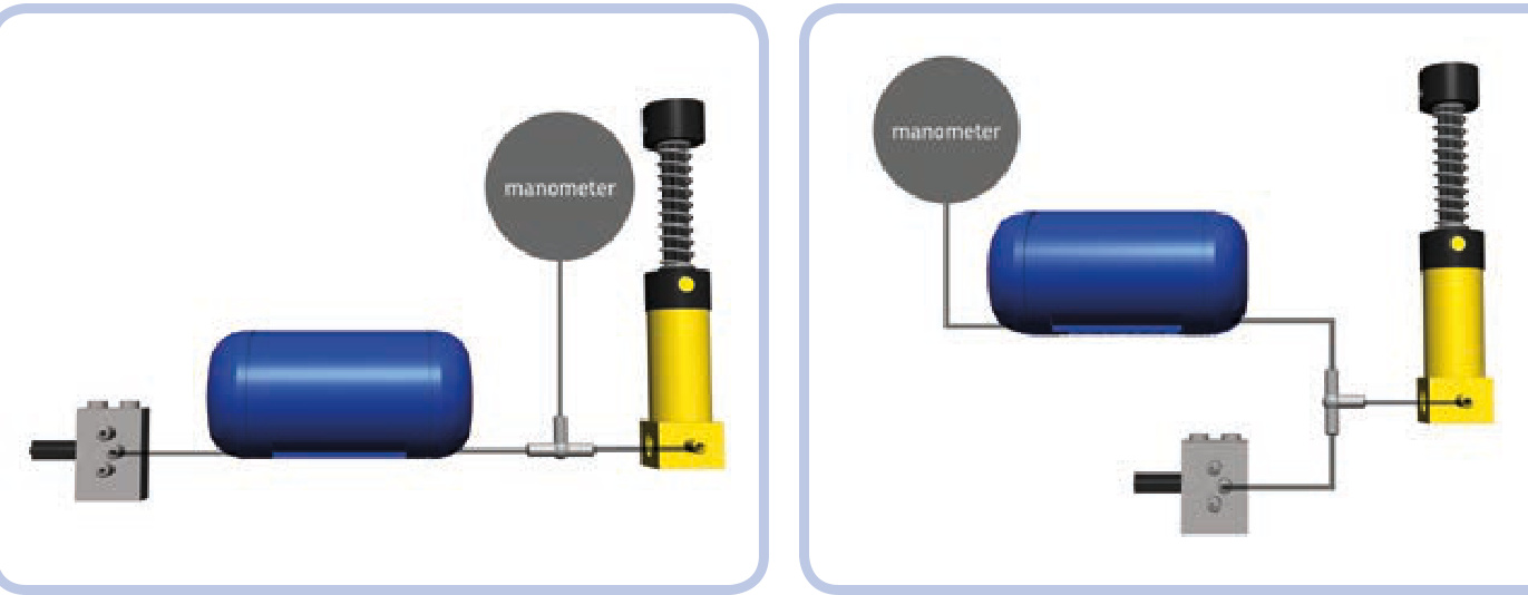
Figure 9-11: Two diagrams showing a pneumatic system with an airtank and a manometer. Notice that both the airtank and the manometer work exactly the same way in both cases.
removing springs to create motorized compressors
Since the large pneumatic pumps are so much more powerful than the small ones, they can be used to advantage in motorized compressors. The one problem you’ll encounter is that the spring in the large pump resists the force of the compressor’s motor and slows the entire mechanism down. To solve this problem, remove the spring by pulling it off the Old large pump or, with the New pump, cutting it (because the contact pad gets in the way).
pneumatic suspensions
In heavy models, you can use the large pneumatic cylinders instead of shock absorbers to create a kind of pneumatic suspension. Depending on the pressure of the air inside them, the cylinders will tend to retract under the load and extend back to their neutral position once the load is reduced or gone.
The advantage of pneumatic suspensions is that they’re tough and they allow you to adjust ground clearance simply by changing the air pressure. But they also have a few disad vantages: Their performance is worse than that of traditional shock absorbers, they’re best used with heavy models, and their pneumatic system needs to be refilled from time to time due to microleaks.
turning your pneumatic system into a hydraulic one
In real life, pneumatic systems are less popular than hydraulic ones. Liquid-filled hydraulic systems are widely used by machines that handle heavy loads, especially construction equipment like excavators, cranes, front-end loaders, backhoes, skid-steer loaders, forklifts, dump trucks, and so on.
If your constructions need to handle heavier loads, you can turn the pneumatic system into a hydraulic one by replacing the air with liquid, although this has to be done carefully. Liquids are much denser than air and much less prone to compression.
Of course, there are certain risks in filling the LEGO pneumatic system with fluid, the most important of which is that you may damage large cylinders: They have metal rods, which can corrode depending on the fluid you use. Also, the rods are covered with grease for lubrication, which may react with the fluid you choose or be removed by it. And even if you use a “safe” fluid, there is still the matter of drying the cylinder after use—a difficult task given that the cylinder is almost fully closed.
The following is a list of tips for using fluids in LEGO pneumatic systems. I’m not recommending that you fill the system with fluid, and if you do so, you may damage your pieces in the process. Remember that if you decide to experiment with fluids, you do so at your own risk. Be advised that when things go wrong, it can get pretty messy!
The best choice of liquid is a mineral oil—a noncorrosive, nonreactive, odorless fluid that is safe for human contact. Mineral oil is 20 percent thinner than water, inexpensive, and available at most drug stores.
You should only convert the New LEGO pneumatic system to hydraulics because the valve is the only exhaust in the system; the fluid will exit only from there instead of exiting from cylinders, as in the Old system.
You’ll need a constant supply of fluid, and the LEGO pumps must be fully submerged in the fluid in order to pump it.
The fluid’s viscosity will improve the way the cylinders handle heavy loads, but this also means that you will need to apply much greater force while pumping.
The integrity of the seals in the pneumatic system is very important when fluid is used. Any leaks can introduce air into the system, which could block its function completely.
Any leak in a fluid-filled pneumatic system can affect its surroundings. Make sure that there are no electric or metal pieces near the pneumatic system in your construction. Also, try to build the system so that if a hose pops off, you can access the hose quickly and block it or lift its end to stop the fluid from leaking out.
Never use the manometer with fluids; you’re likely to damage it permanently.
It’s very difficult to dry the insides of pneumatic pieces unless you disassemble them. Pumping warm air through them continuously for a prolonged period of time will help; you can also try leaving them for a while in a bag of uncooked rice, as rice absorbs moisture.
This chapter presents devices that make creative use of pneumatic systems: motorized compressors, remotecontrolled valves, and pneumatic engines. All these devices take advantage of the fact that the pneumatic system has been designed to be customizable, and there’s almost no limit to potential modifications.
In this chapter, we’ll start by discussing the most basic and versatile devices and then move on to more sophisticated and specialized ones.
motorized compressors
10
A compressor is a stand-alone mechanism that provides a continuous supply of pressurized air—for example, the massive air compressor you can find at the gas station (for reinflating tires) or the portable model you might use to inflate an air mattress. The most practical and popular method of building a Technic compressor is by driving small LEGO pumps with a motor. This method allows us to control a compressor remotely, and it ensures that the compressor works at a constant rate, making the cylinders in a pneumatic system move smoothly.
It’s convenient to keep the motor attached directly to a compressor. This allows us to place the whole mechanism practically anywhere in our construction, as we are not bound by driveshafts, gears, or any other rigid elements. Our only limitation is finding a home for the electric wire and pneumatic hose.
There is one issue worth keeping in mind when building a motorized compressor: its ripple. LEGO pumps work in a cycle: They are retracted, pumping air into their outlets, and then extended, taking air from outside. In other words, they don’t provide air constantly but only during exactly half of the
pneumatic devices
cycle. This cycle has two consequences that become more significant as the number of pumps working simultaneously increases: fluctuating air flow and vibrations, which result from the pumps’ rods being repeatedly pushed back and forth.
Some builders are fond of building monstrous compressors with eight or more pumps driven by the RC motor (shown in Figure 10-1). This is not always the best solution, as RC motors are large, loud, and power consuming. Another solution is to divide pumps into groups that work alternately. For example, instead of four pumps working as one, we can use two pumps that are retracted while the
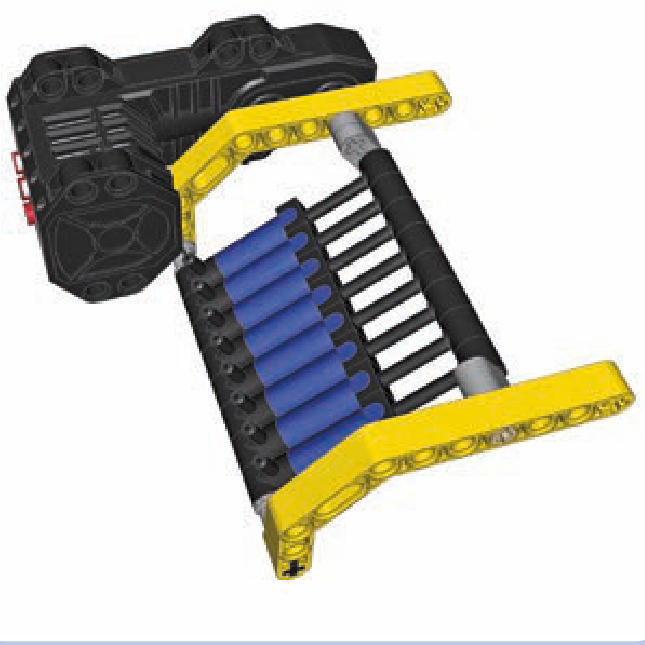
Figure 10-1: An eight-pump compressor driven by the RC motor. This design is a real monstrosity in the world of LEGO compressors.
other two are extended. Ideally, we should have multiple pumps that are fully out of phase because this limits both the load on the compressor’s motor and the vibrations the compressor creates. Supporting the pumps’ ends as rigidly as possible also reduces vibrations.
You might ask why we would want to use so many pumps in the first place. It’s because a single pump has a very small capacity and is, therefore, not very powerful, taking quite a while to fill just a single large pneumatic cylinder. How fast your pneumatic system operates depends on the volume of pressurized air delivered to it, so using many pumps is a natural solution. The rule of thumb is that for a pneumatic system in which one or two large cylinders are working at the same time, it takes at least two pumps for a PF Medium motor to provide air pressure at reasonable rate.
Not e All of the compressor designs in this chapter are intended for pumps that are 5.5 studs long when extended, not for the newer 6-stud-long version. This longer version is found only in a single set and is therefore quite rare.
Figures 10-2 through 10-6 show various compressor designs that drive more than one pump.
The rocking compressor, shown in Figure 10-6, can hold from 2 to 18 pumps, depending on the length of its axles. It moves the pumps in a reciprocating motion, rather than the rotary motion used in other compressors, which results in a more compact build. Moreover, it has a gearing with four possible gear combinations (see Figure 10-7).
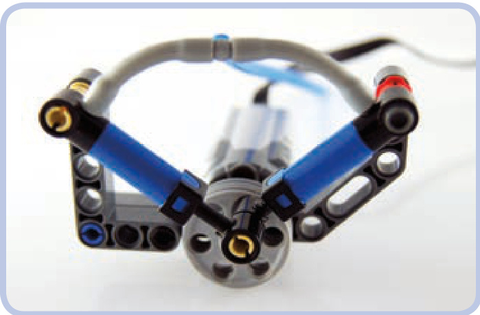
Figure 10-2: A compressor with two pumps that work alternately, both attached to two wedge belt wheels. The design is small, but it’s difficult to add more pumps to it. In this compressor, the pumps are 90 degrees out of phase rather than 180 degrees, so the pressure is still “uneven.” In other words, one pump is not fully extended while the other is fully compressed.
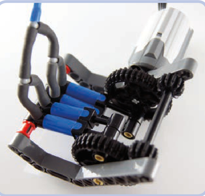
Figure 10-3: A compressor that can hold two or four pumps while making use of two 36-tooth gears. The orientation of the gears relative to each other is maintained by two 12-tooth gears on a separate axle, which also transfers drive between them. It’s possible to connect two or more such compressors side by side to increase the number of pumps.
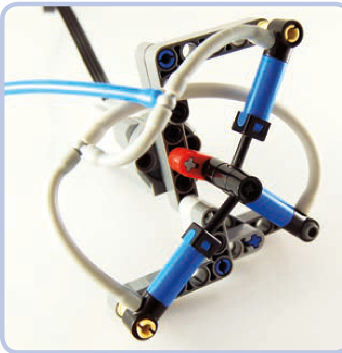
Figure 10-4: It’s perfectly possible to split pumps in a compressor into three groups.
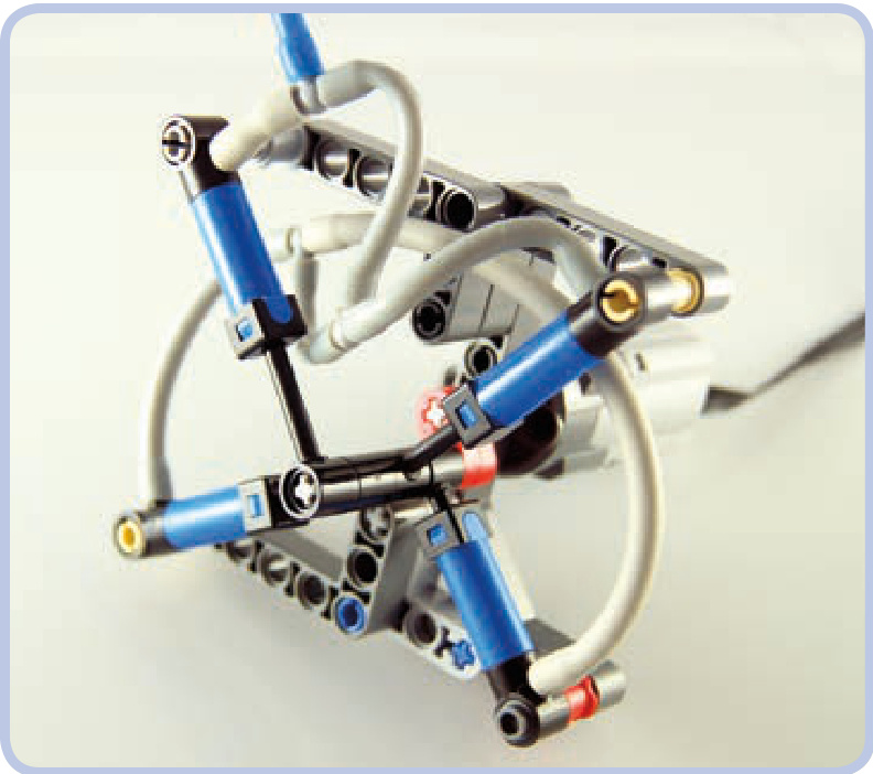
Figure 10-5: You can even split pumps in a compressor into four groups at various points of the working cycle. But such compressors are significantly more complex while working only a little more smoothly.
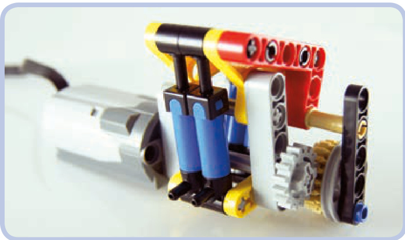
Figure 10-6: Finally, here’s a design called a rocking compressor. While it doesn’t extend pumps to their maximum, it can hold up to 18 pumps in two alternating groups.
Figure 10-7: The four gear combinations suitable for the rocking compressor, with their ratios labeled
a rocking compressor
Here’s a look at the complete building instructions for a simple design. The blue axles limit the number of pumps, but making the axles 1 stud longer adds space for two more
pumps. For clarity, the instructions show the compressor without pumps, but the pumps should be mounted on the blue axles.
motorized valves
The purpose of motorizing a pneumatic valve is simple: remote control. A valve can be connected to a motor in a simple way, preferably with the use of a 24-tooth gear with a clutch, which prevents the motor from stalling (see Figure 10-8). Once the 24-tooth gear can no longer drive the valve, the grey circle inside the gear begins to rotate instead, which prevents damage to the motor or to the gearing.
Polish builder Maciej “dmac” Szyman´ski discovered that if we use this exact combination of motor and gears with a regular 24-tooth gear (without a clutch), we’ll get a returnto-center motorized valve—that is, a valve that returns to
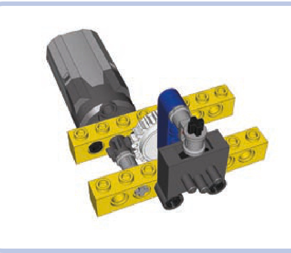
Figure 10-8: A simple way to motorize a pneumatic valve is to use a gear with a clutch for the motor’s safety.
central position the moment the motor stops, thereby shutting down the valve (see Figure 10-9).
But precision is often crucial when switching pneumatic valves. The designs above lack precision, while the design shown in Figure 10-10 offers plenty of fine-grained control. This is useful for retracting heavily loaded cylinders, when the valve has to be opened little by little to prevent cylinders from yielding to the load.
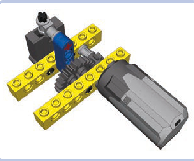
Figure 10-9: With a regular 24-tooth gear instead of the clutch gear, we get a return-to-center valve.
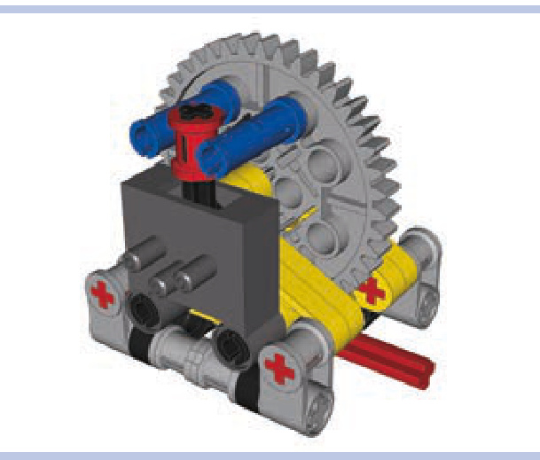
Figure 10-10: This high-precision valve-switching mechanism makes use of a worm gear and a 40-tooth gear to ensure accuracy. The red bush on the valve’s lever improves it further by reducing backlash. Note that there is no safety clutch in this assembly; because the mechanism multiplies the motor’s torque by a factor of 40, there is a chance that some pieces may be damaged if the motor doesn’t stop at the right moment. To lessen this risk, a clutch can be added between the valve and the motor.
autovalve
An autovalve combines the functions of a motorized valve with those of a compressor. It makes use of the compressor’s ability to function regardless of the input’s direction of rotation—we’ll use the motor’s direction of rotation to control the valve itself. After switching, the motor can continue to drive the compressor as long as is needed.
The autovalve’s working principle is based on a socalled sliding worm gear, as shown in Figure 10-11. The motor drives the compressor through an axle on which a worm gear is located. The worm gear drives one of two identical short axles with a 12-tooth gear and a short beam (shown in green). The beams act as pushing elements: Each of them can push the valve’s lever in one direction and then continue rotating freely. But when driven in the opposite direction, the beam locks against the lever, stopping the respective axle and making the worm gear slide away from it. The worm gear slides until it meshes with the other axle’s gear, at which point it starts to drive it and the other pusher located on it, effectively switching the valve.
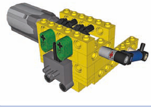
Figure 10-11: An autovalve uses a sliding worm gear to control a compressor and a pneumatic valve with just one motor.
The disadvantages of the autovalve include a long switching time, which can be remedied by driving the input faster, and the limit of one valve and one compressor per motor. Still, the compressor can be connected to any pneumatic system, with more valves controlled separately (see Figure 10-12).
To see an autovalve in action, visit http://www.youtube .com/watch?v=OsDJ4iTs-P8.
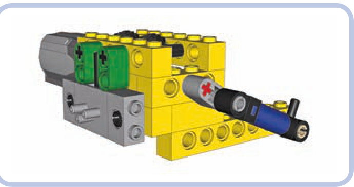
Figure 10-12: An autovalve can be created with both types of pneumatic valves (the older one is shown here) and with any compressor whatsoever— the single-pump compressor here is just an example.
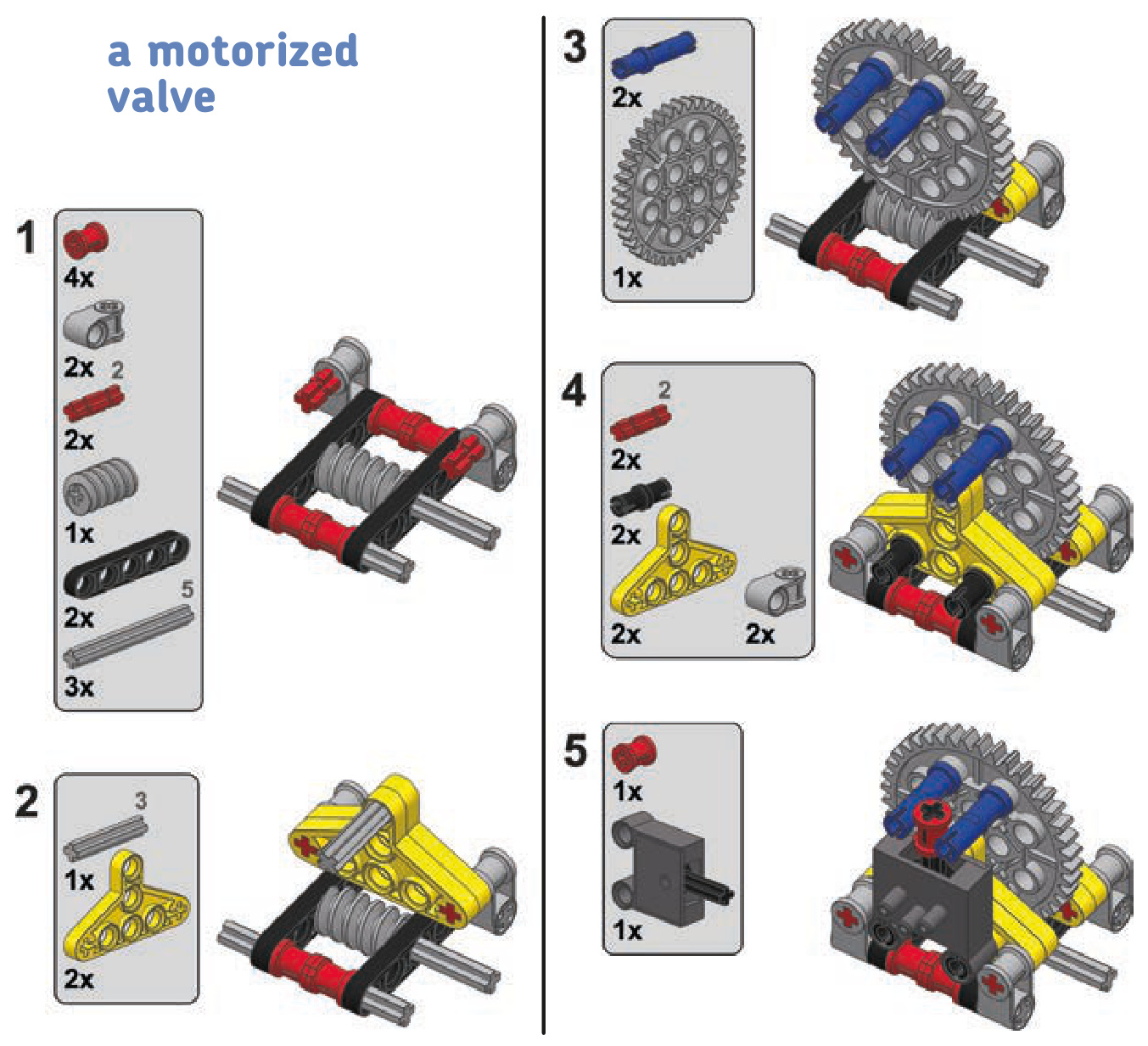
an autovalve
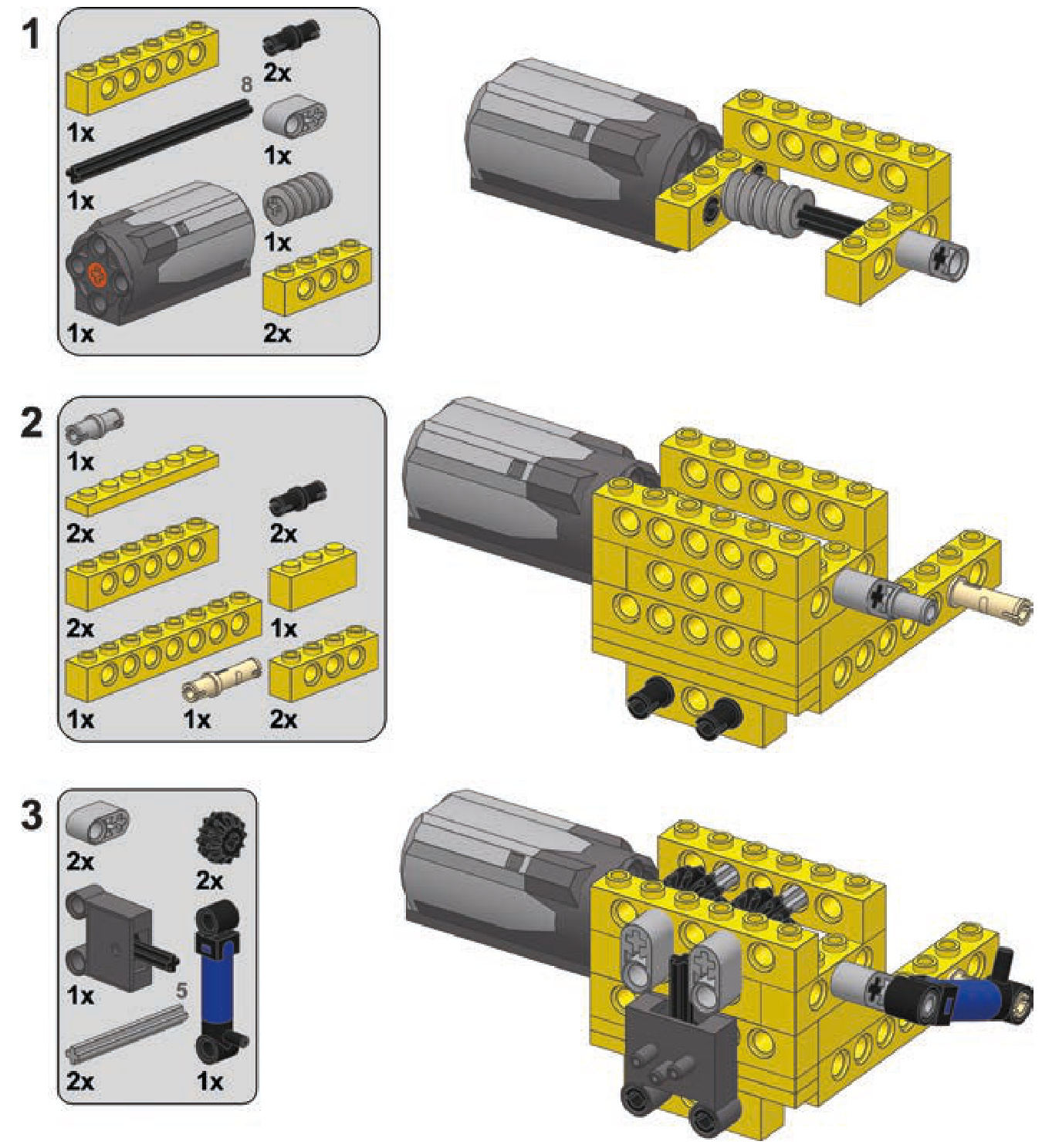
automated pressure switch
Having a motorized compressor in your pneumatic system doesn’t necessarily solve your pressure problems. Complex pneumatic systems with many cylinders working in turns can require large amounts of pressurized air in the system at one moment and no air moments later. While the amount of air pressure that goes into a system can be managed by building a compressor fast and/or large enough, constantly turning it on and off can be an onerous task.
The solution to this problem is a pressure switch, also known as a pressure limiter. We can build one using a PF switch, a small pneumatic cylinder, and a rubber band.
How does a pressure switch work? Take a look at Fig ure 10-13, which shows how the switch connects the com pressor motor to the power supply. The cylinder’s lower port is connected to the pneumatic system, while the upper one is left open. A rubber band is put over the cylinder, keeping it retracted. If the pressure in the pneumatic system is high enough, the cylinder will overcome the rubber band and
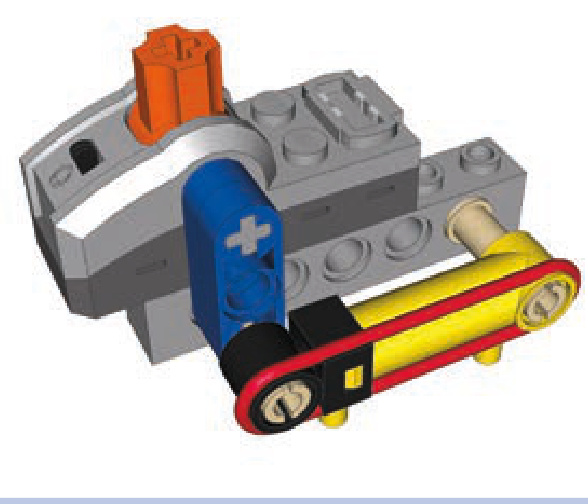
Figure 10-13: A close-up view of a pressure switch. The switch usually needs adjusting to activate at the desired pressure threshold. It can be fine-tuned by adjusting the rubber band’s strength, the angle of the cylinder relative to the lever, and the length of the lever. It is also possible to use old 9V switches, which offer less resistance, or to use multiple cylinders. Large cylinders can be used as well, although their large capacity makes them less sensitive and therefore less useful in system that must react to small changes in air pressure.
extend. If the pressure drops, it will yield to the band and retract. This means that if we connect the cylinder to the PF switch, the switch can effectively control the compressor’s motor, turning it on automatically when pressure is low and then turning it off when it’s high enough. Such a mechanism is best used with an airtank, filling it automatically when necessary.
The pressure switch works best when close to the airtank, which, in turn, should be close to the compressor, as shown in Figure 10-14. Some builders create complete modules with the motorized compressor, airtank, and pressure switch all put together. I prefer to take advantage of the elastic elements—that is, the wires and hoses—to be able to adjust the location of these elements more freely. A singular module has fixed dimensions, while separate elements con nected only by wires and hoses can be fitted into limited space in different ways, allowing for less massive and more creative housings.
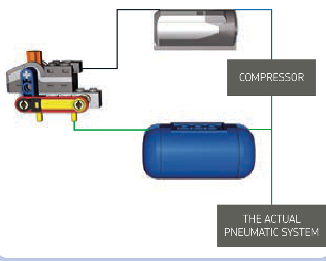
Figure 10-14: The general scheme of the pressure switch and its connections to other components of the pneumatic system. Black lines mark electric wires, blue lines mark mechanical connections, and green lines mark pneumatic hoses.
A properly built and adjusted pressure switch leaves you with only pneumatic valves to take care of; the compressor works automatically, and the pressure in the airtank is maintained at all times. Note that there is no particular place where the switch-airtank-compressor combination should be connected to the rest of the pneumatic system. Such a connection can be placed between the compressor and airtank, between the airtank and pressure switch, after the airtank (as shown in Figure 10-13), or after the pressure switch— it will work just the same regardless of placement. You can also connect a LEGO manometer to observe the relationship between air pressure and the functioning of the switch.
pneumatic engines
The functioning of pneumatic cylinders is somewhat similar to that of the pistons in an internal combustion engine, allowing us to build a compressed air engine with cylinders driving the crankshaft. Such an engine, sometimes called a LEGO pneumatic engine (LPE), is powered by pressurized air delivered to the cylinders. Pneumatic engines are advantageous in terms of their performance, resemblance to combustion engines, and sound, which is quite loud and carlike compared to that of electric motors. What makes these engines appealing to many builders is their complexity, which creates almost endless possibilities for improvements. While the complexity of these engines may be appealing, they’re also quite a challenge to build. Disadvantages of pneumatic engines include their size and their need to be constantly connected to a compressor. Moreover, pneumatic engines work only in one direction, and they get warm from the friction of many moving parts and from air being compressed inside the cylinders.
The working principle of a pneumatic engine is simple: A cylinder is connected to a shaft with a cam so that extending it rotates the shaft by a half rotation and retracting it rotates the shaft by another half rotation (see Figures 10-15 and 10-16). The same shaft uses another cam connected to a valve to switch the cylinder between extending and retracting continuously, thus creating a complete working cycle. The cycle, therefore, involves both cylinder and valve and goes as follows: Cylinder extends to maximum, valve is switched, cylinder retracts to maximum, valve is switched.
The problem with the cycle is that both cylinder and valve have dead spots, or points of the cycle at which they can stop, as shown in Figure 10-17. For a cylinder, it’s the point when it’s extended or retracted to maximum, and for a valve, it’s the point when it goes through neutral position and no air comes through it. If we make an engine with just one cylinder and one valve, these dead spots will overlap and effectively stop the engine after it makes just half a rotation. This can be prevented by using a heavy flywheel and a modified valve.
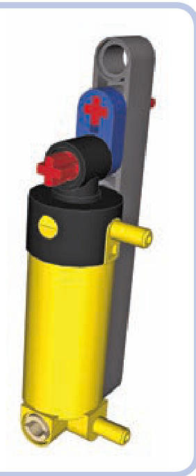
Figure 10-15: A simple way to connect the cylinder to a shaft is to use a cam made of a short beam. However, a cylinder can extend by 4 studs, but here it’s allowed to extend by only 3.
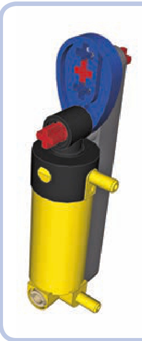
Figure 10-16: To make the cylinder extend fully, we need its tip to be mounted 1.5 studs away from the shaft. A piece called a Technic cam allows this.
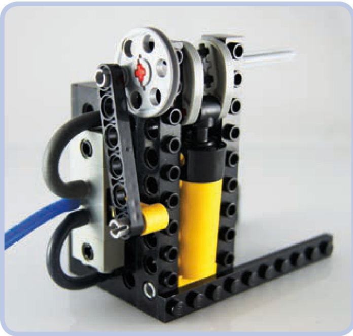
Figure 10-17: A simple cylinder and valve combination with two cranks: one made of Technic cams, converting the cylinder’s motion into the crankshaft’s rotation, and another made of a wedge-belt wheel, using the crankshaft’s rotation to switch the valve back and forth. Note that both cylinder and valve are in dead spots here.
Modifying LEGO pieces is actually quite common among advanced LPE builders. The best pneumatic engines from these builders can far outperform any LEGO electric motor in terms of both speed and torque, but that performance comes at a cost. In such engines, cylinders’ ports are often drilled to increase throughput; the valves’ internal structure is cut to reduce their switching resistance; and many moving parts, such as cylinders and camshafts, are lubricated. Industrial tubing with clamps replaces LEGO hoses and is sometimes glued to the ports. Finally, these engines are powered with non-LEGO compressors, such as electric compressors for car tires. LEGO pneumatic pieces were simply not designed to move quickly, and there is a lot of friction involved in the many moving pieces of a pneumatic engine, which justifies modifications for some builders.
Getting back to our single-cylinder engine, a modified valve and a flywheel can make it work: The flywheel will provide the momentum necessary to get the engine through dead spots, while the valve will offer minimum resistance and thus minimum risk of getting stuck in a dead spot (see Figure 10-18). Such an engine needs to be started by spinning the flywheel manually, but it will keep running for as long as it receives sufficiently high air pressure.
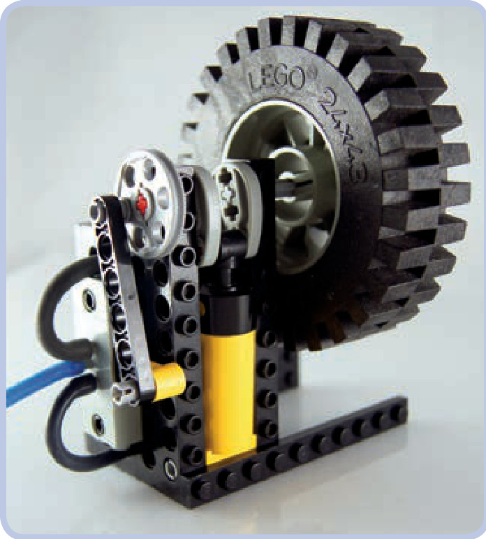
Figure 10-18: This is the engine from Figure 10-17 with a flywheel added to keep it running through overlapping dead spots. Starting such an engine is a little finicky, but it works fine once it gets going.
a single-cylinder engine
Here are the building instructions for the engine shown in Figure 10-18. Like every set of engine instructions in this chapter, these instructions have both the cylinder and hoses removed for clarity. In this BI, a photo shows the cylinder’s position and a connection scheme for the hoses. Remember that engines like this work best with a large volume of continuous air pressure, and they are difficult to drive with a LEGO compressor.
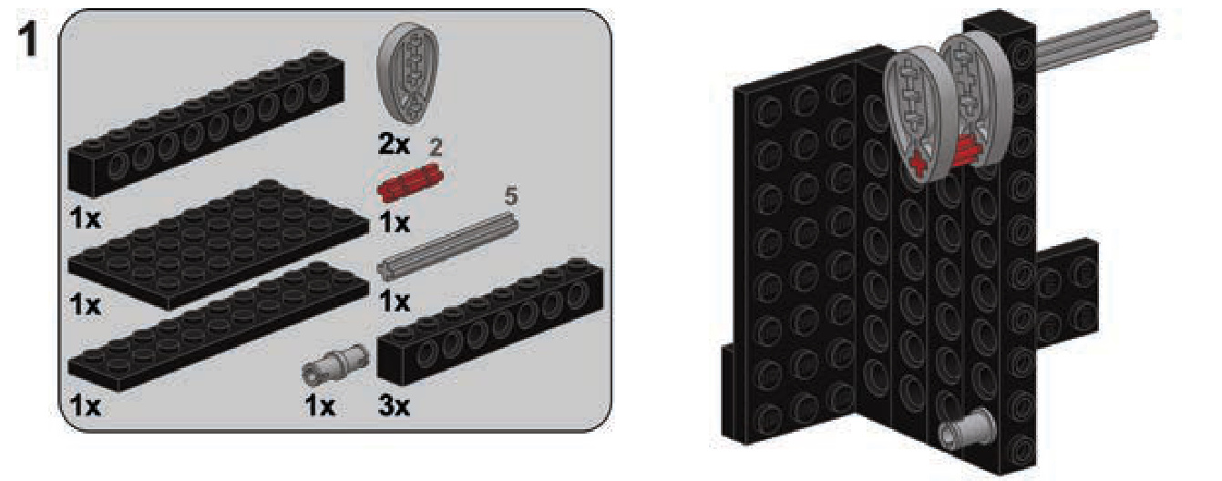
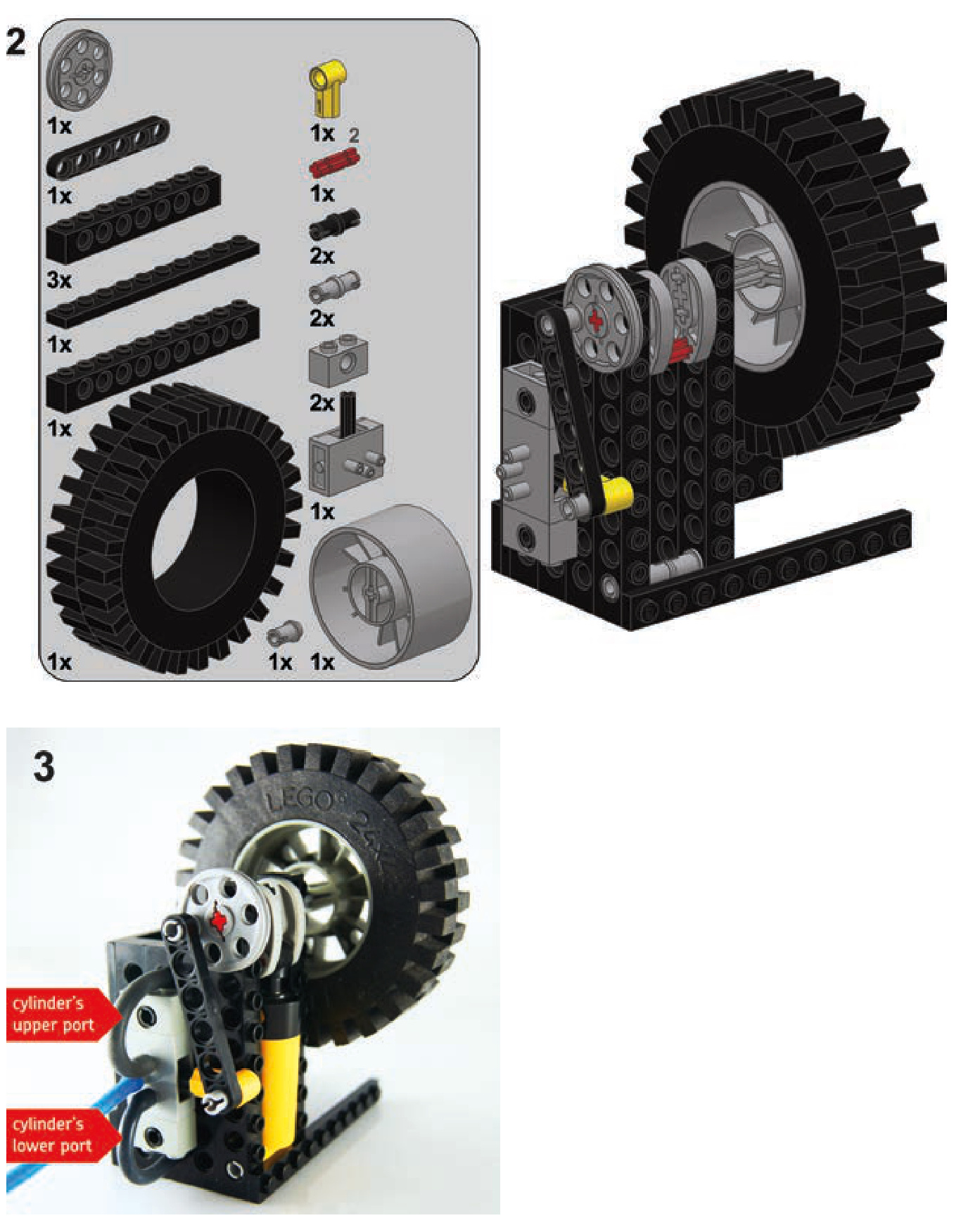
Engines with two, four, six, or more cylinders can be built as follows: The cylinders are split in two groups, each group connected to one valve so that there are two valves in the engine for any number of cylinders. At any given time, one group of cylinders is retracting while the other is extending. These groups should be mixed so that no two cylinders of the same group are next to each other. All the cylinders are connected to a common camshaft, but with cams rotated 90 degrees relative to the adjacent ones (see Figure 10-19). This reduces the overlap of the cylinders’ dead spots. Finally, each valve is connected to the end of the camshaft closest to the group of cylinders connected to the other valve, as shown in Figure 10-20. This arrangement ensures that we don’t overlap dead spots between a valve and the cylinders connected to it.
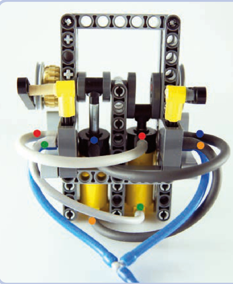
Figure 10-19: A two-cylinder engine built in accordance with the rules above. The colored dots show which ports are connected. Note the position of the cams. The engine can start all by itself and runs relatively smoothly. The tan gear can transfer drive from the engine. More cylinders can be added to the engine, and it reaches optimum smoothness with four cylinders, each with a cam rotated 90 degrees relative to the next one.
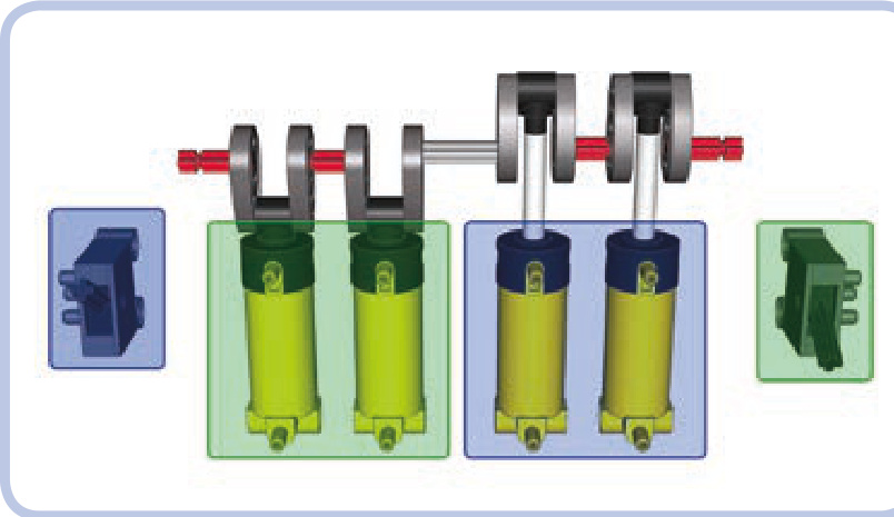
Figure 10-20: A simplified layout of a four-cylinder pneumatic engine: All cylinders, running the same camshaft, are split into two groups (marked green and blue), each connected to a single valve. The valves are connected to the sides of the camshaft nearest to the opposite group.
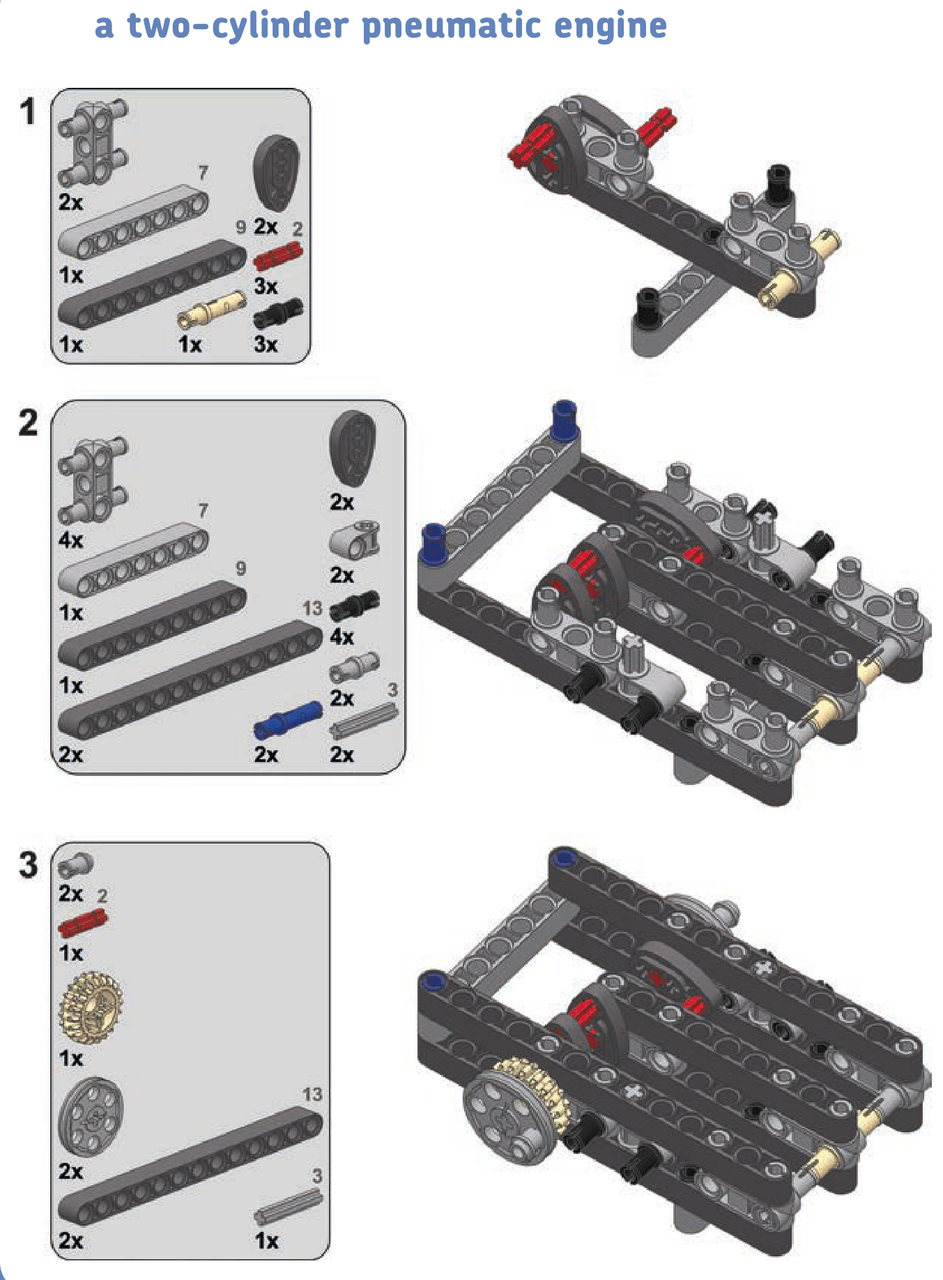
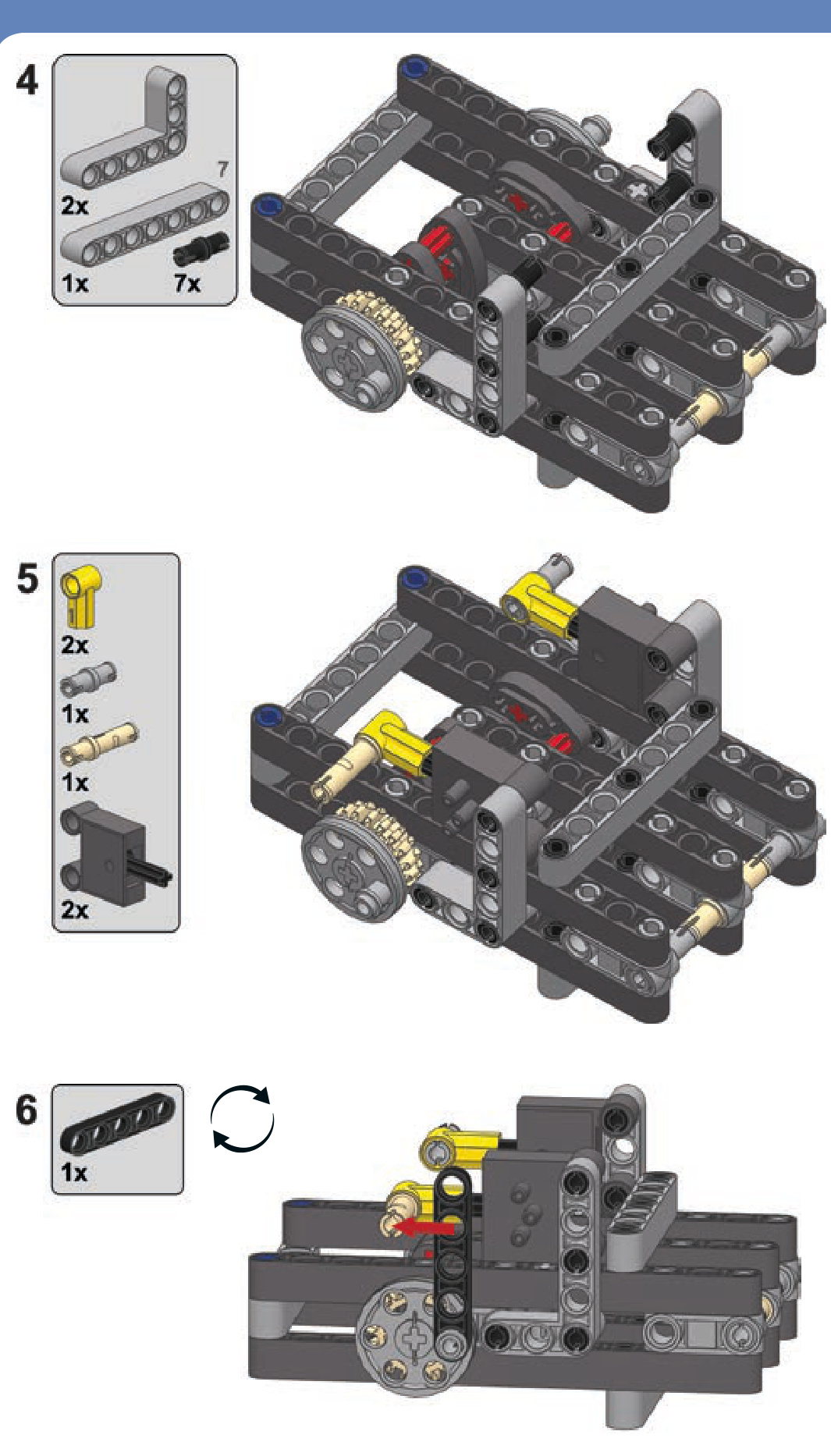
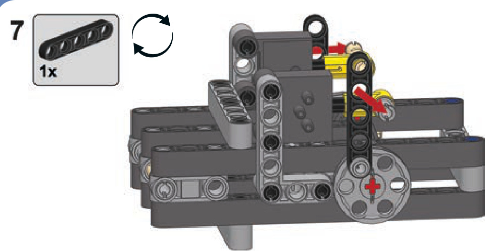
In general, the more cylinders we add, the smoother the engine will run. The engine reaches optimum performance when we use at least four cylinders, each with its cam rotated 90 degrees relative to the adjacent ones (see Figure 10-21). On the other hand, adding more cylinders will result in a greater combined engine capacity, which will in turn increase fuel consumption. Note that the efficiency of LEGO compressors is poor compared to the capacity of such an engine. Note also that the engine’s efficiency can’t be improved by using airtanks because the engine needs a constant supply of equally pressurized air and airtanks provide only a single, short blast of very highly pressurized air. You can, of course, build an engine with a separate valve for each cylinder. Some builders do that for smoother operation, but it drastically increases the overall complexity of the engine.
One last issue is that cams are quite fragile when sub jected directly to the cylinder’s power. This problem can be remedied by using sliders—that is, elements that move together with the tip of the cylinder and thereby transfer movement to the cams (see Figure 10-22). Sliders keep a cylinder’s tip moving in a straight line, and this creates a more favorable distribution of force, leaving the cams less stressed. The use of sliders is also more efficient because the cylinder’s power is not wasted by tilting it sideways; instead, all of the power is transferred to the cam. Additionally, with cylinders maintaining the same position, it’s possible to pack them more tightly. Sliders are very popular in complex engines—especially in those in the V system— as they allow a sturdier overall construction.
Figure 10-21: The “optimum crankshaft,” with four cams, each rotated 90 degrees relative to the next one, provides the smoothest operation possible for a pneumatic engine.
Figure 10-22: A two-cylinder engine with sliders. The colored dots show which ports are connected. The sliders are built around the red pieces, each moving along two light grey axles. They keep the cylinders’ motion in a straight line and then transfer the motion to the cams (blue). Note that the extension of the cylinders is limited to 3 studs rather than 4, but thanks to this limitation, the sliders can also be used to control the valves.
a two-cylinder pneumatic engine with sliders
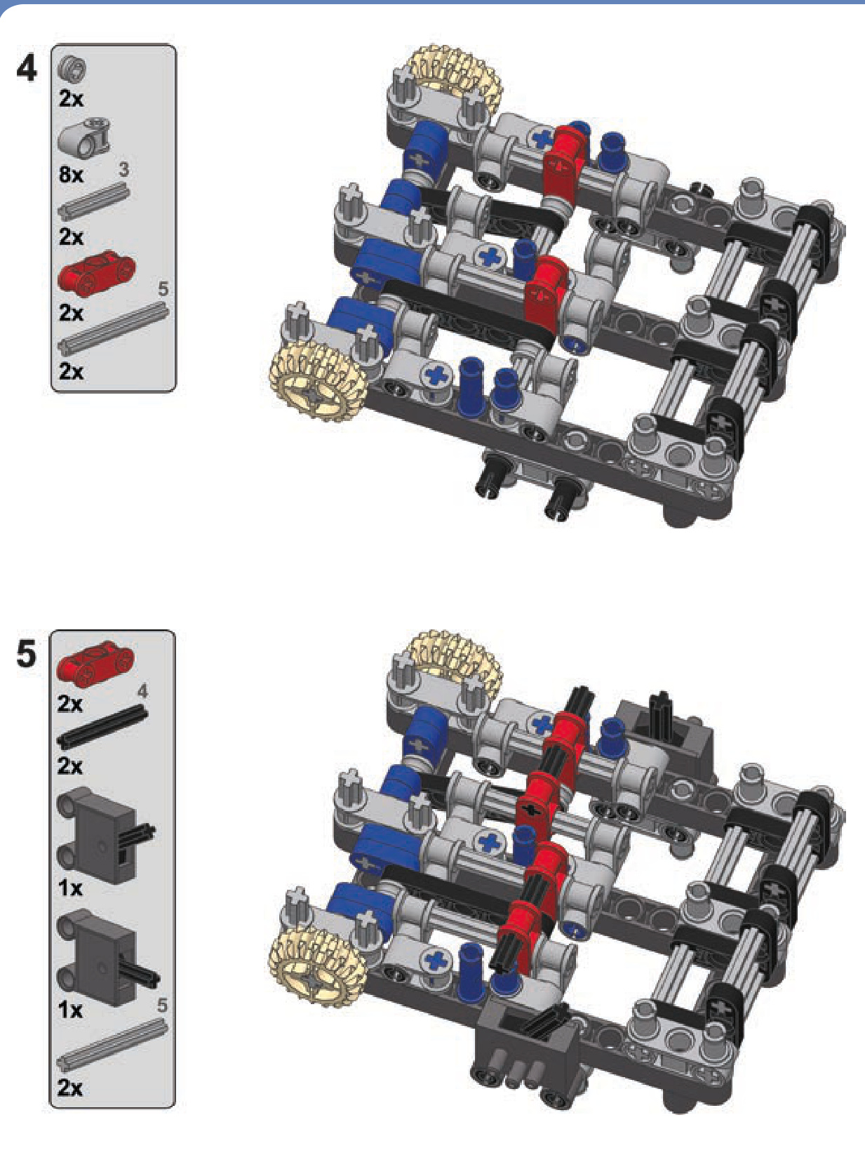
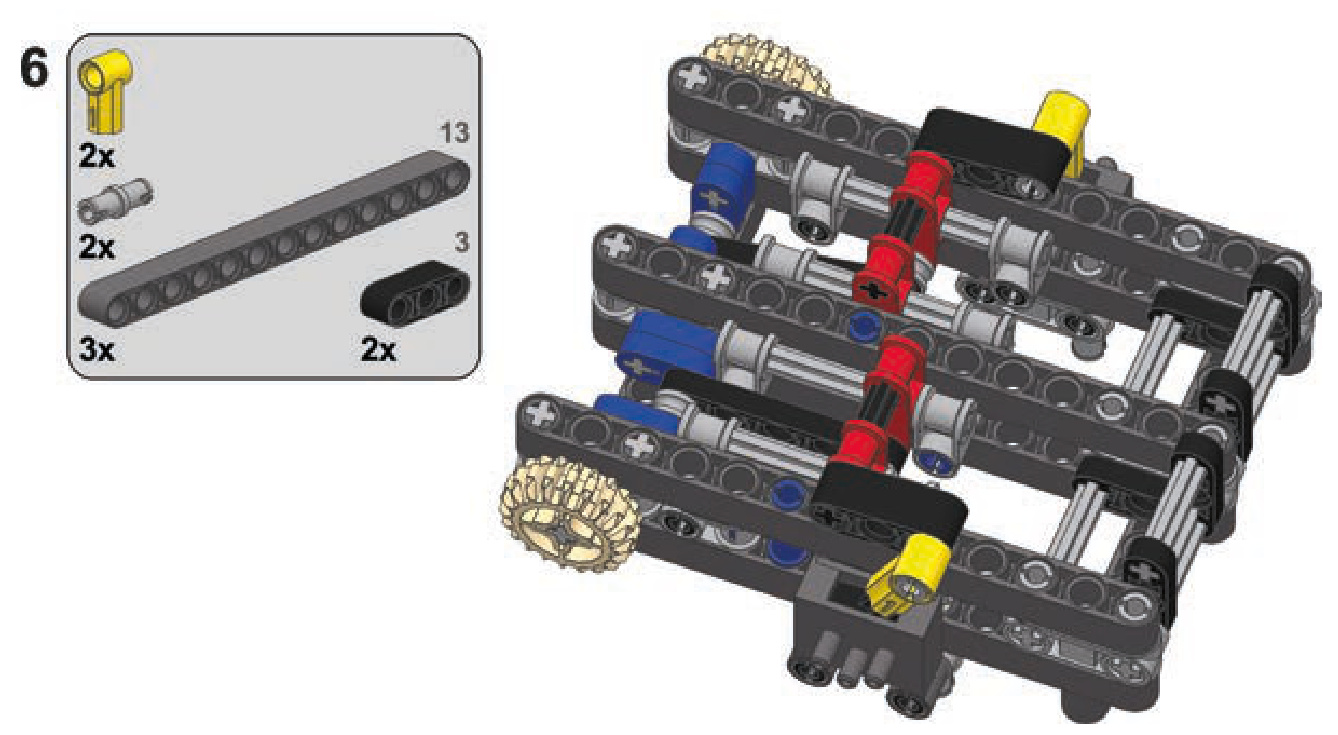
Engines in the V configuration are engines with cylinders aligned in two planes that form the shape of a letter V when viewed along the axis of their common camshaft. These engines can be built in two ways, both of which require building two identical modules with cylinders lined up and connecting them at a right angle. The first way is to build them with two separate crankshafts, each for one module, and to then use gears with a single central shaft to connect the modules. The second way is to use a single common crankshaft for both modules and to then connect two cylinders to each single crank pin. Since we want to keep the modules aligned (as they are in real engines), it’s easier to use half-stud-thick beams to connect sliders to the cams rather than use 1-stud-thick cylinder tips (see Figure 10-23).
The possibilities with pneumatic engines are vast and include engines in W, boxer, and even radial systems. You can find many ingenious variants shown in detail by visiting Dr. Dude’s YouTube channel: http://www.youtube.com/user/ DrDudeNL/. Dr. Dude, a Dutch builder, has been a fan of the LEGO Technic set—and of big Technic cars in particular—for over 30 years.
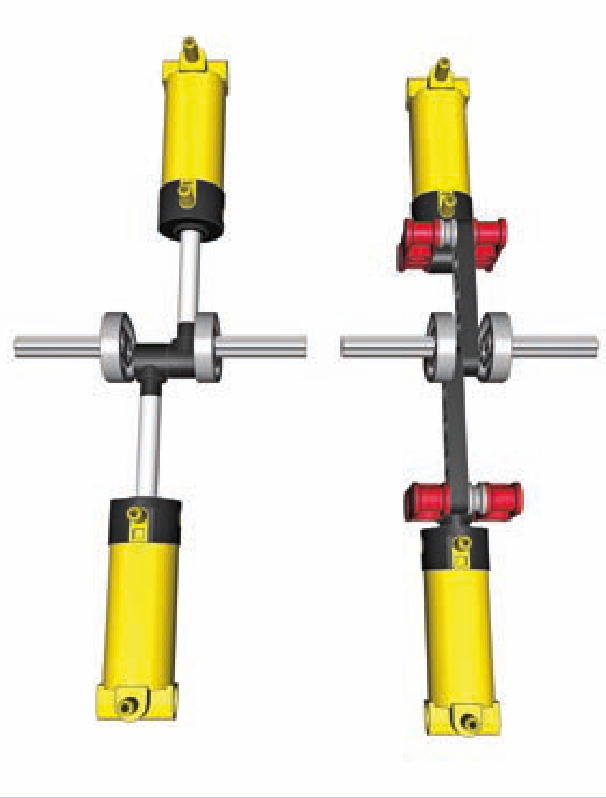
Figure 10-23: Two cylinders connected to a single cam directly (left) and through sliders (right). You can see that the sliders allow the cylinders to stay aligned, while direct connection forces one of them to be moved by 1 stud.
builder showcase
Many LEGO builders produce impressive pneumatic engines, but one of them is the unquestionable master in this field: Alex “Nicjasno” Zorko. Alex builds big and heavy models of sports cars and found LEGO motors too weak to drive them. He has developed incredibly advanced motors, including “simple” inline engines, a V6 that operates at speeds well above 2000 RPM, and a V8 strong enough to make even a very heavy model drift (shown in Figure 10-24). Alex shows his models at http://nicjasno.com/ and sells his engines at http://lpepower.com/.
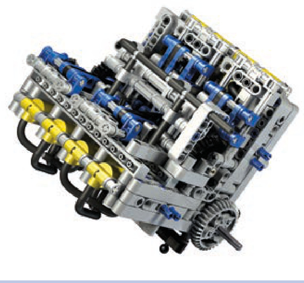
Figure 10-24: Alex “Nicjasno” Zorko’s V8 motor
a working water pressure pump
While LEGO Technic creations don’t mix well with fluids, it is possible to build a pneumatic pump that will work with water while ensuring that no sensitive pieces come into physical contact with liquid. This pump uses pressurized air to push water, making it fairly safe and simple to use in, for example, a LEGO fire engine model.
To create a water pressure pump, we need an airtight container that will initially be filled with water and will then have pressurized air delivered to it. Using LEGO pieces for such a container may not be the best idea; a small bottle with a metal or plastic cap is a better alternative.
The working idea of this pressure pump is that by delivering air into a closed, water-filled container, we can force the water out. The container therefore needs an entry for the air and an exit for the water. The entry can be anywhere in the container; the exit should be at the bottom to stay in contact with water as long as possible.
We can adapt our bottle by making two holes in the cap and putting two hoses through them, as shown in Figure 10-25. One hose (dark grey) will deliver air and can end just below the cap or go deeper into the bottle—it doesn’t matter. The other hose (blue) will be the water’s way out, and it should reach all the way to the bottom. It’s a good idea to make the other hose stiff so that it doesn’t float in the water; a rigid LEGO hose or a regular drinking straw can be used. The hardest part is making the cap airtight with hoses going through it. You can achieve this by using modeling clay, masking sol, or molten wax from a candle.
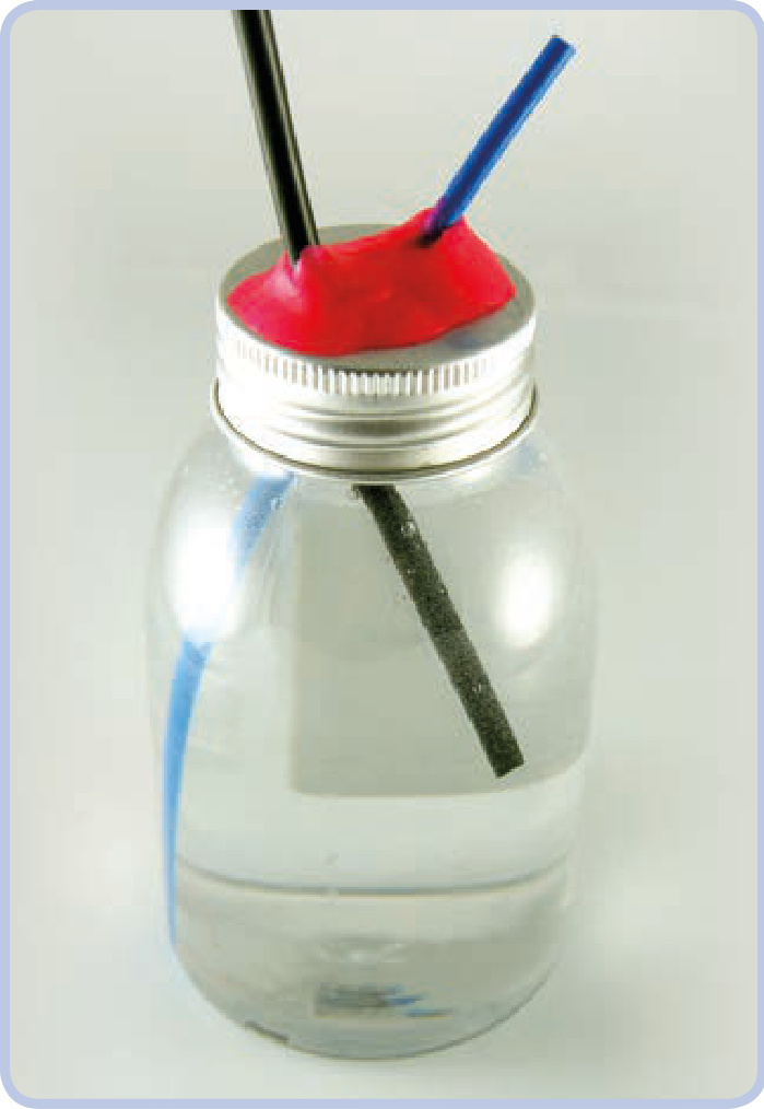
Figure 10-25: A small plastic bottle with a metal cap makes for a very good container. The dark grey elastic hose delivers air, while the blue rigid one lets the water out (note that it can be extended by putting another elastic hose on its end). The cap was punctured in two places to let the hoses through and then sealed with modeling clay (pink).
Now you can connect the first hose to any compressor, and the water will spurt from the other one. Note that water is much less compressive than air, so it will take very high air pressure to make water really spurt. You can make your pump more effective by delivering air to it faster and by making the exit hose narrow. You can also use an airtank full of pressurized air and connect it to the first hose through a pneumatic valve; opening the valve will empty it into the bottle in an instant.
Just make sure the water doesn’t come out anywhere near the electric components of your construction!
There was a time when Technic bricks alone could support and hold together almost any motorized mechanism. But eventually LEGO introduced stronger motors with enough torque to push even Technic brick connections apart. Having more torque at our disposal is an advantage in all aspects except one—it requires structural reinforcing, adding extra pieces whose primary purpose is to hold other pieces together (see Figure 11-1). A properly reinforced mechanism stays together regardless of its motor’s strength and how much load is applied to its output, even if the load stalls the motor.
This chapter explores how to find places in a structure where reinforcing is crucial; how to identify strong and weak LEGO pieces; and how to create casings, chassis, frames, and trusses to support your models.
why things fall apart
In order to find where and how to reinforce our structures, we first have to understand why pieces come apart. When we house a mechanism inside a structure, it has an input, an output, and points of attachment to that structure; most often this means we have axles with gears that are housed in a structure’s pin holes, as shown in Figure 11-2. Whenever a mechanism works, it handles a load that exerts stress on its output and has to be overcome by the force applied to its input. For example, if our mechanism is a drive train, the motor driving its input has to overcome the stress exerted by its wheels—the rolling resistance and friction. This means that there are basically two forces in our mechanism, one applied to its input and one applied to its output, and that they work against each other. In other words, the output resists the input, creating stress that is carried through every component between them.
11
building strong
Figure 11-1: The two red beams hold the yellow Technic bricks together. Without these beams, the powerful PF XL motor would push the lower brick away the moment it started running.
Figure 11-2: An example of a mechanism with a motor driving a wheel. The mechanism consists of six gears in three pairs on four axles, and it’s housed inside Technic bricks held together by plates.
Let’s think of this mechanism as a chain, with input and output being the first and last links. The initial force applied to the input (the first link) will be transferred through the chain and will stop on the link of least resistance. If the structure around our mechanism is solid, all links will have more resistance than the mechanism’s output (the last link of the chain), and the mechanism will work as intended: Only the output will yield to the input. But if any link of our chain before the output has less resistance than the output, it will be dislocated and separated from the next link, thus breaking the chain and preventing the mechanism from working.
finding weak links
So let’s find the weak link in our chain. In our example from Figure 11-2, we have a motor connected to the axle, an axle connected to the 8-tooth gear, an 8-tooth gear connected to the 24-tooth gear, and so on, all the way to the output and the wheel.
Most of the axle pairs (or other connections) in this chain are within a single LEGO brick. But the connection marked by red arrows in Figure 11-3 involves two Technic bricks, meaning that when stress is applied, it can break apart (as shown in Figure 11-4). When deciding where to reinforce your model, look for the seams that could separate under stress.
Also note that a pair of gears that increases the gear ratio (the driver gear is bigger than the follower) is more likely to come apart than a pair that decreases the gear ratio (the driver gear is smaller than the follower). There is simply more force exerted on the follower gear when gearing up, and such a pair of gears is a good candidate for reinforcing.
Figure 11-5 shows one obvious way to reinforce our mechanism: We simply replace the two pairs of bricks with two bricks. On the upside, the weak seam is now gone, every link in our chain is solid, and we no longer need to use plates. Additionally, this solution adds no weight and takes up no extra space. The downside is that using long, solid bricks can be an invasive way of reinforcing, and building in this way is time-consuming and extremely inconvenient with complex gearing, as you’ll have to place all elements at the same time.
Figures 11-6 and 11-7 show another way we can reinforce our mechanism: by adding support beams. This increases the weight of the mechanism and takes more space, but it involves only minimal changes to the original structure. Note that structures like the one shown in Fig ure 11-7 have the downside of added friction because the yellow bricks are partially supported by the axles—building compact mechanisms can come with a cost.
Figure 11-3: The critical connection in the mechanism from Figure 13-2 is marked by a red arrow here. This connection lies between two separate bricks and is held together merely by the clutching force of two plates (yellow); therefore, it can be broken easily.
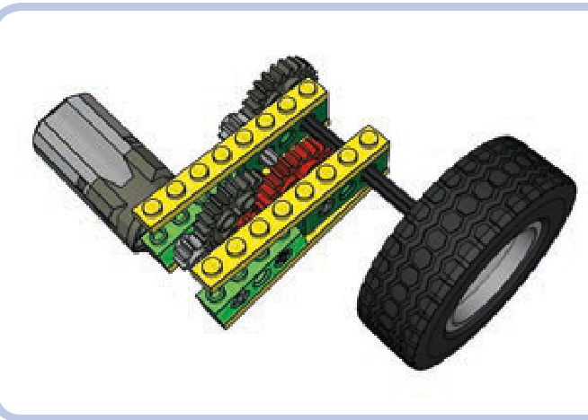
Figure 11-4: Without reinforcement, the weak link breaks apart the surrounding structure. The red gears are no longer meshed, and the mechanism fails.
understanding where to reinforce
The direction of a stressed gear’s displacement depends on its location and its direction of rotation. When one gear drives another that resists it, the driver gear pushes against the follower gear just as the follower gear pushes back. This principle, which you might remember from high school physics, is a case of Newton’s law of action and reaction, which states that forces are generated in equal and opposite pairs. Figure 11-8 shows a driver gear on top, rotating clockwise (as marked by the black arrow), and a follower gear on the bottom, being pushed down and to the side at the same time (as marked by the blue arrows).
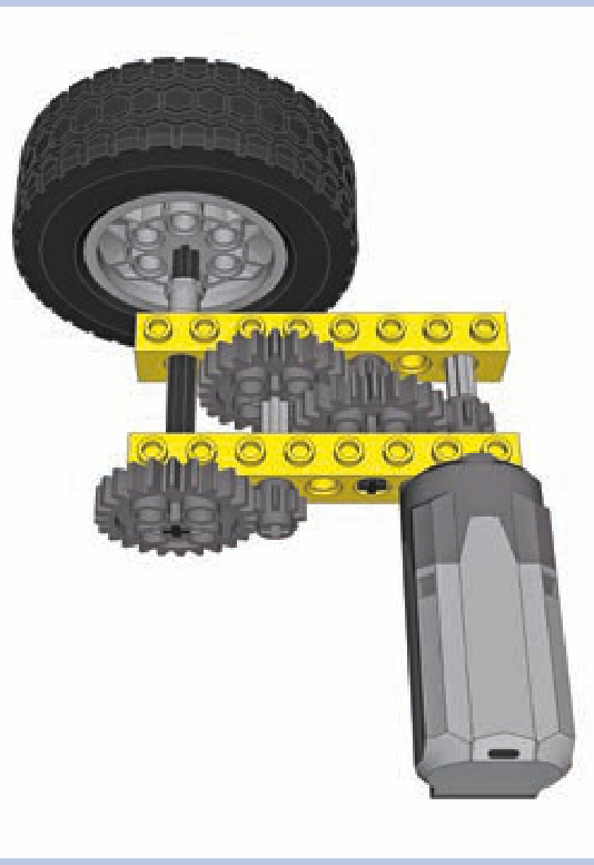
Figure 11-5: The two pairs of bricks from our original structure have been replaced with two single, solid 1×8 bricks.
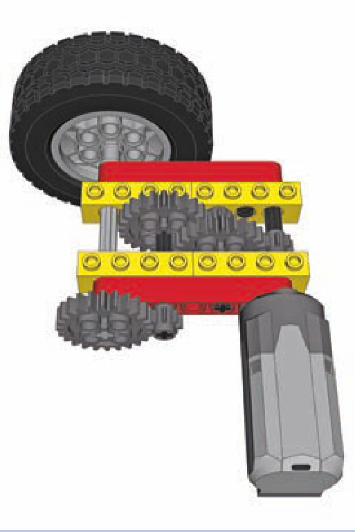
Figure 11-7: If vertical space is limited, horizontal beams (red) can some times be used. In this case, doing so requires using a few longer axles and moving the motor 1 stud away from the bricks. Note that in order to create a rigid connection, each of the bricks is attached to the beams at two points.
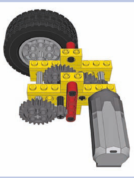
Figure 11-6: Vertical beams (red) are a popular means of reinforcement.
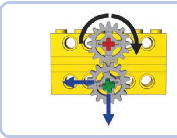
Figure 11-8: Directions of forces (blue) exerted by a driver gear (top) on the follower gear (bottom)
Now, if there were nothing holding the bricks in Figure 11-8 together, the follower gear would be pushed downward and to the left. The key to reinforcing properly is to limit displacement in both directions: Pieces that can’t be separated can still be rotated, displacing and misaligning important elements of our drivetrain.
This same principle applies when two gears are mated at a different angle, as shown in Figure 11-9. Note that the gears in this figure can’t come apart because their axles are both housed in a single L-shaped beam.
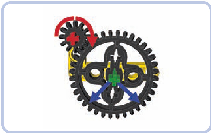
Figure 11-9: The directions of force exerted on the follower gear, which is located below and to the side of the driver gear
the right way to reinforce
Now that we know how to find weak links in our mechanisms, let’s look at some examples of reinforcing. Figures 11-10 to 11-14 show reinforcing done poorly and done properly.
As you can see, reinforcing gears can be boiled down to making sure the axles are securely supported. But since axles can be long and prone to bending, there are two rules to follow here:
N The axle should be supported at least at two points. N The axle should be supported as close to the gears on it as possible, preferably from both sides of the gears.
Figure 11-15 illustrates the first rule, and Figure 11-16 illustrates the second rule. Axles are in fact much less rigid than beams or bricks, and they can bend, twist, or even slide through the gears when subjected to sufficient stress.
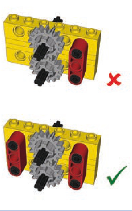
Figure 11-10: Holding one end of the bricks together doesn’t create a rigid connection, but holding both does.
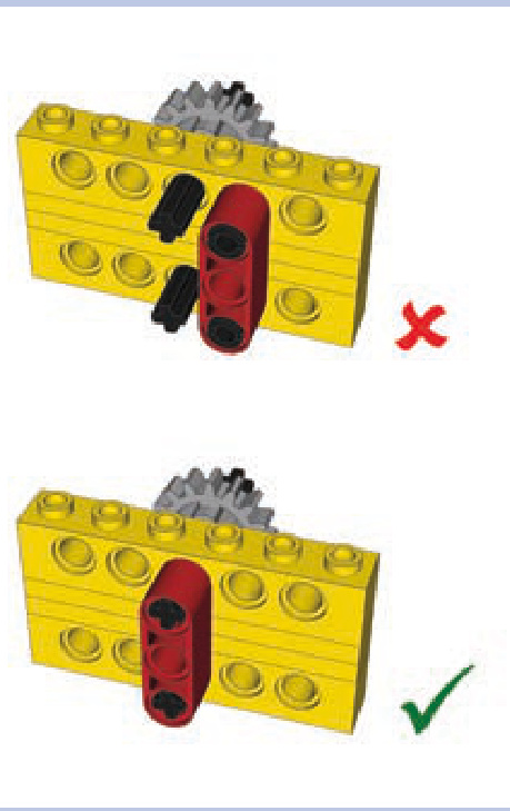
Figure 11-11: It’s possible to reduce the number of reinforcing pieces by aligning them to the meshed gears rather than pairing them.
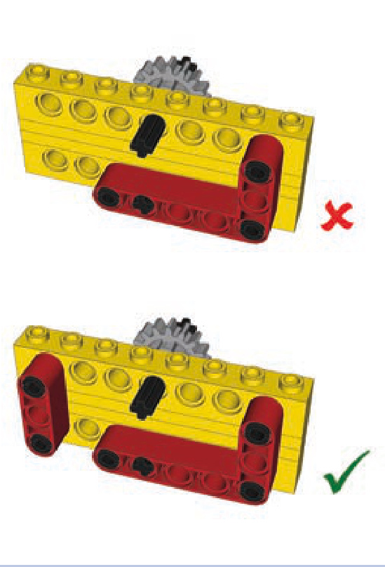
Figure 11-12: The L-shaped beam alone is not enough to create a rigid connection because it has only one point of attachment to the upper brick.
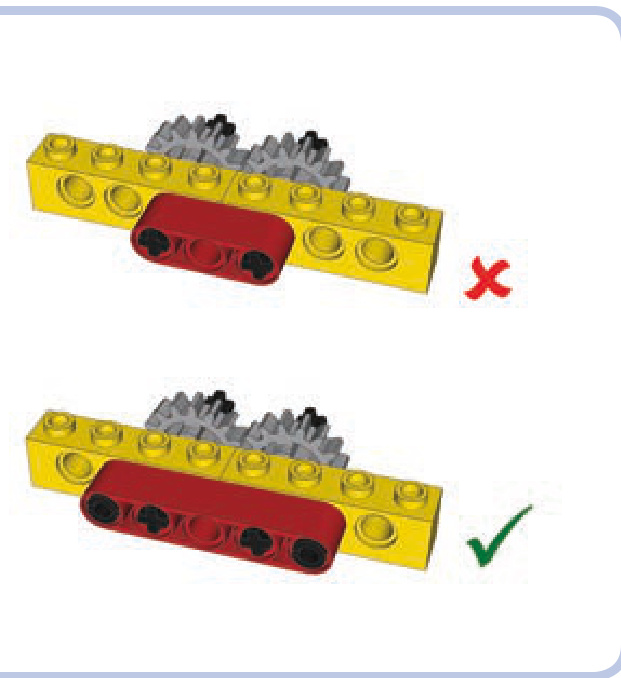
Figure 11-13: Beams that have only one point of attachment to adjacent bricks don’t create a rigid connection. At least two points of connection to each brick are needed.
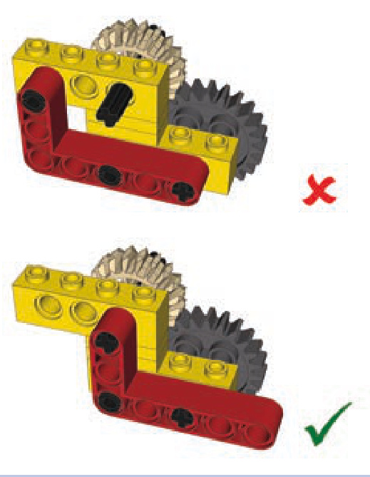
Figure 11-14: Plates help to create rigid connections. Use them as spacers between the points of connections of two bricks to prevent the bricks from oscillating.
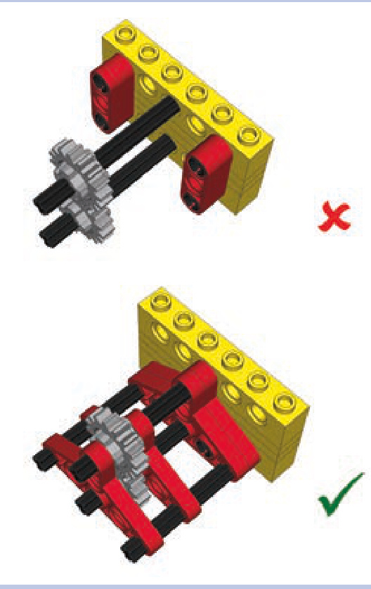
Figure 11-15: Both ends of the axles need to be reinforced to prevent the gears on them from coming apart.
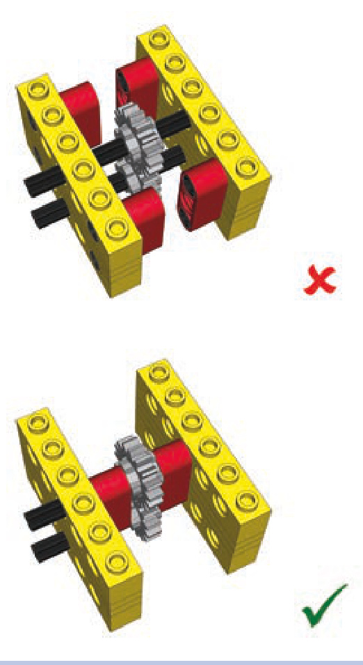
Figure 11-16: Empty space on the axles adjacent to the gears allows them to slide or enables the whole axle to bend. This empty space should be used for reinforcement.
Figure 11-17 shows a permanently twisted axle. Note that the longer the axle, the more easily it gets twisted—that’s why it’s always a good idea to swap a single long axle for a few shorter ones connected with axle joiners. Another good idea is to add substantial gear reduction near the output so that only a small portion of the drivetrain is subjected to high torque.
Reinforcing perpendicular bevel gears is a more difficult task, as even a minimal displacement in structure disengages the gears. This is because their teeth come into contact over a small area. We need to make sure the gears are firmly kept in place. A number of LEGO studfull and studless pieces are designed specifically to reinforce perpendicular gears, as shown in Figures 11-18 to 11-20.
Figure 11-17: Axles are much more elastic than they might seem. This one has been twisted permanently by a PF XL motor.
When you have no dedicated LEGO pieces to reinforce perpendicular gears, you can still use basic pieces to do so. Figures 11-21 and 11-22 show examples of this approach using studfull and studless pieces.
things to remember when reinforcing
There are a few more rules of reinforcing worth keeping in mind:
Minimal reinforcement is the best reinforcement. Extra pieces add weight and take up space.
If a seam or joint can separate, it eventually will—and usually when you least expect it. (And Murphy’s law says that it will be deep inside your MOC where you can’t fix it!)
N Real reinforcement doesn’t yield until pieces physically break.
When building, think about disassembly, too. A reinforce ment that has to be cut to be taken apart will cost you pieces.
The last rule is no less important than the ones pre ceding it. It’s fairly easy to connect LEGO pieces in such a way that the resulting structure is impossible to disassemble without cutting some of the pieces. Figure 11-23 shows some examples. As you’ll see, you should take precautions when inserting axles—always make sure it’s possible to pull or push them out.
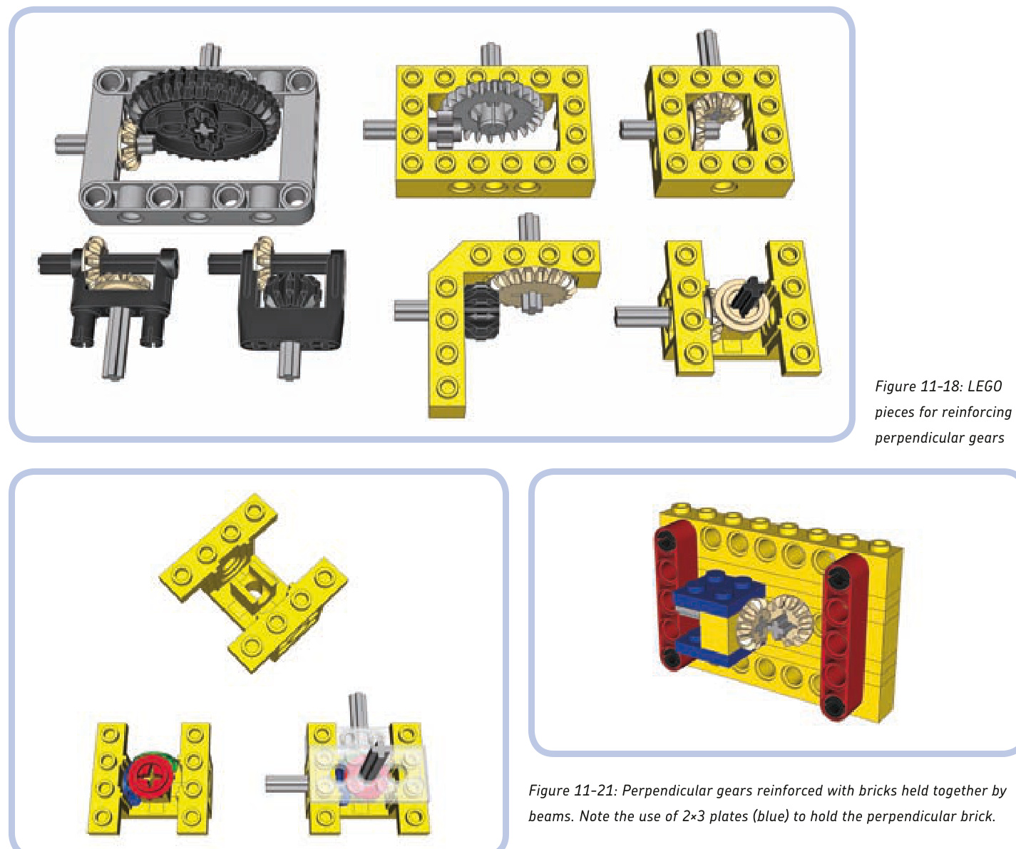
Figure 11-19: Piece #6585 is a particularly interesting brace that can reinforce both horizontal and vertical gears. Technic bricks and plates can be connected to it to support their axles.
Figure 11-20: There are also so-called Technic gearboxes, which have special sturdy bevel gears enclosed. They are robust and can have axles inserted into them, but they are rare.
Figure 11-22: Perpendicular gears reinforced with L-shaped beams. Note that one end of the beams is held together by a vertical beam. This is because there are only axles on this end of the beams and the axles don’t hold the beams together. The other end of the beams has a connector with pins that hold the beams together with a force very unlikely to be overcome by gears.
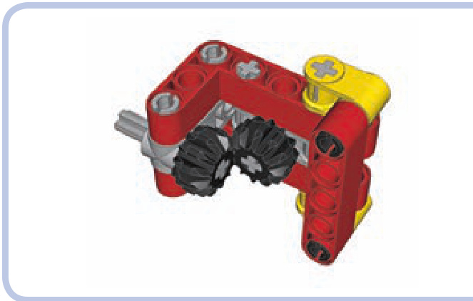
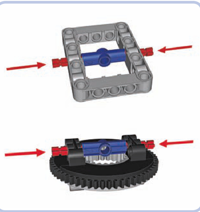
Figure 11-23: Dangerous structures: Once the axles marked by arrows are pushed in, these structures are impossible to take apart without cutting pieces.
reinforced differential casings
Differentials are often subjected to high torque because there is usually no gear reduction between them and the wheels. To make things worse, they are usually meshed using perpendicular gears. It was only in 2009 that LEGO released pieces designed specifically to remedy this problem: studless frames. But studless frames aren’t very common and work only with the newest type of differential gear, as shown in Figures 11-24 and 11-25.
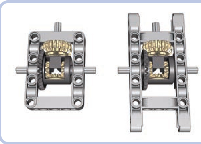
Figure 11-24: The studless frame comes in a regular (left) and an extended (right) variant. Both create a perfectly rigid reinforcement for the newest type of LEGO differential.
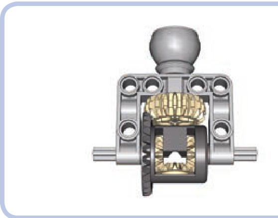
Figure 11-25: The larger part of the ball joint comes with an attached C-shaped frame, large enough to house the newest type of LEGO differential.
four reinforced differential casings
The following are examples of sturdy casings for all types of differentials, made of common pieces. They are inevitably inferior to studless frames because of their greater size and weight, but they are useful nonetheless.
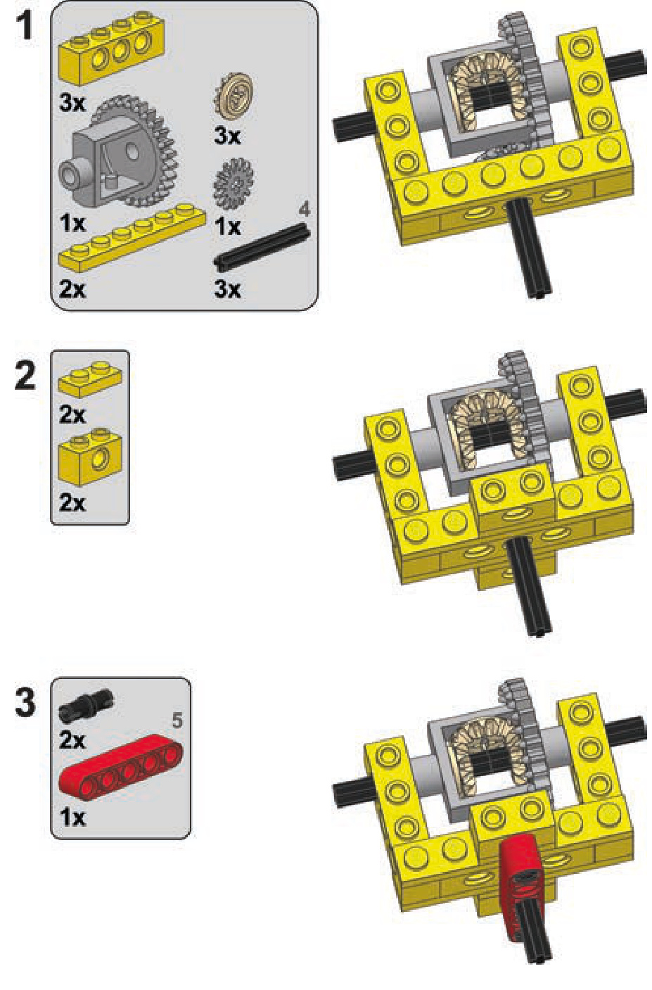
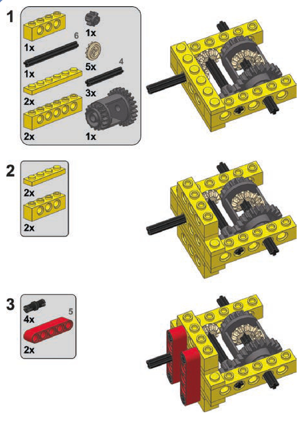
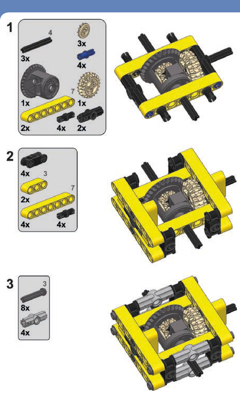
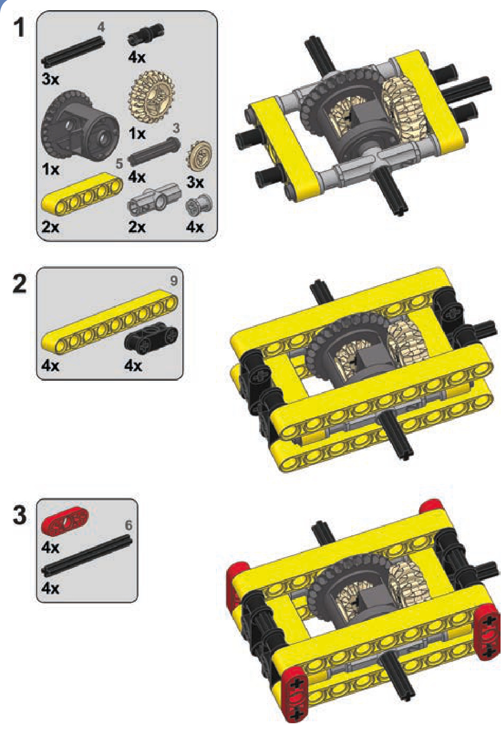
reinforced worm gear casings
Because of their unique design, worm gears need particularly solid reinforcement. As Figure 11-26 shows, apart from pushing the follower gear away, worm gears have a strong tendency to slide along the axle they’re sitting on. This is a result of worm gears’ enlarged axle holes, which allow them to slide along axles. This lateral force can be strong enough to make a worm gear drill through adjacent pieces if sufficiently high torque is applied to it for a prolonged time!
LEGO released special casings for worm gears, but they are relatively large and work only with 24-tooth follower gears, as shown in Figures 11-27 and 11-28.
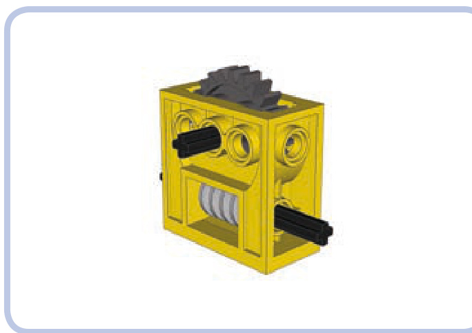
Figure 11-27: The LEGO casing for the worm gear is very sturdy and quite common, but it works only with a 24-tooth follower gear. It’s also better suited for studfull structures than for studless ones.
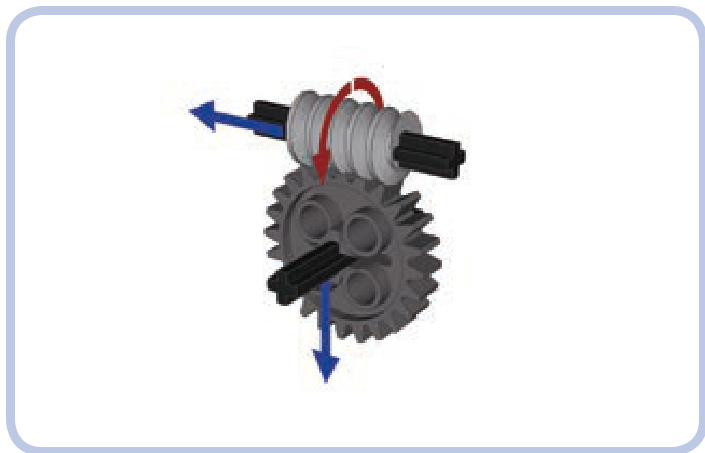
Figure 11-26: The directions of forces exerted by a worm gear. Unlike regular gears, a worm gear doesn’t push the follower gear to the side; instead, it pushes itself against the follower gear along its axle.
Figure 11-28: A gearbox with a worm gear and 24-tooth follower gear closed inside. It’s even sturdier than the regular casing, but it’s very rare.
three reinforced worm gear casings
Thankfully, if you have neither a casing piece nor a gearbox piece, you can easily build your own. Three designs for worm gear casings (using various follower gears) are shown here.
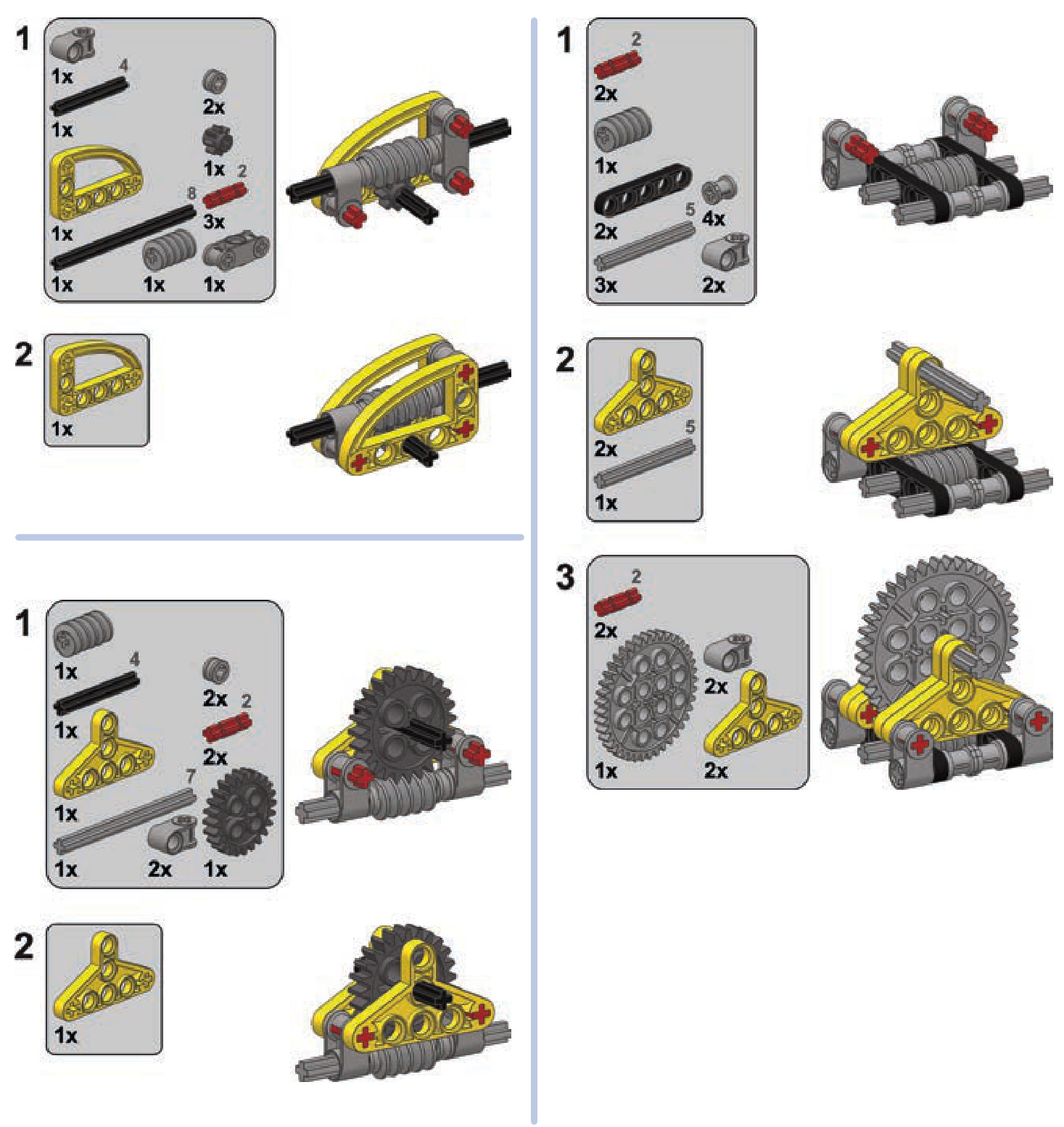
load-bearing structures
Load-bearing structures are the “skeletons” within our models. You might think of these structures as the framing of a house, the pylons of a suspension bridge, the chassis of a car, or even the bones within the human body. They support a construction’s weight and maintain its rigidity, and they may have no other purpose beyond structural reinforcement.
rails, chassis, and body frames
A chassis is the type of a load-bearing structure most commonly used in vehicular models. A properly built chassis is sturdy enough to support the weight of the vehicle and rigid enough to maintain its shape as the vehicle negotiates obstacles and carries loads.
We’re going to focus on the most convenient and commonly used way to build a chassis: rails, also called stringers. Almost all LEGO Technic sets use this method.
相关页面
图片总数:197 张