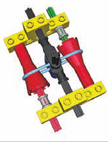
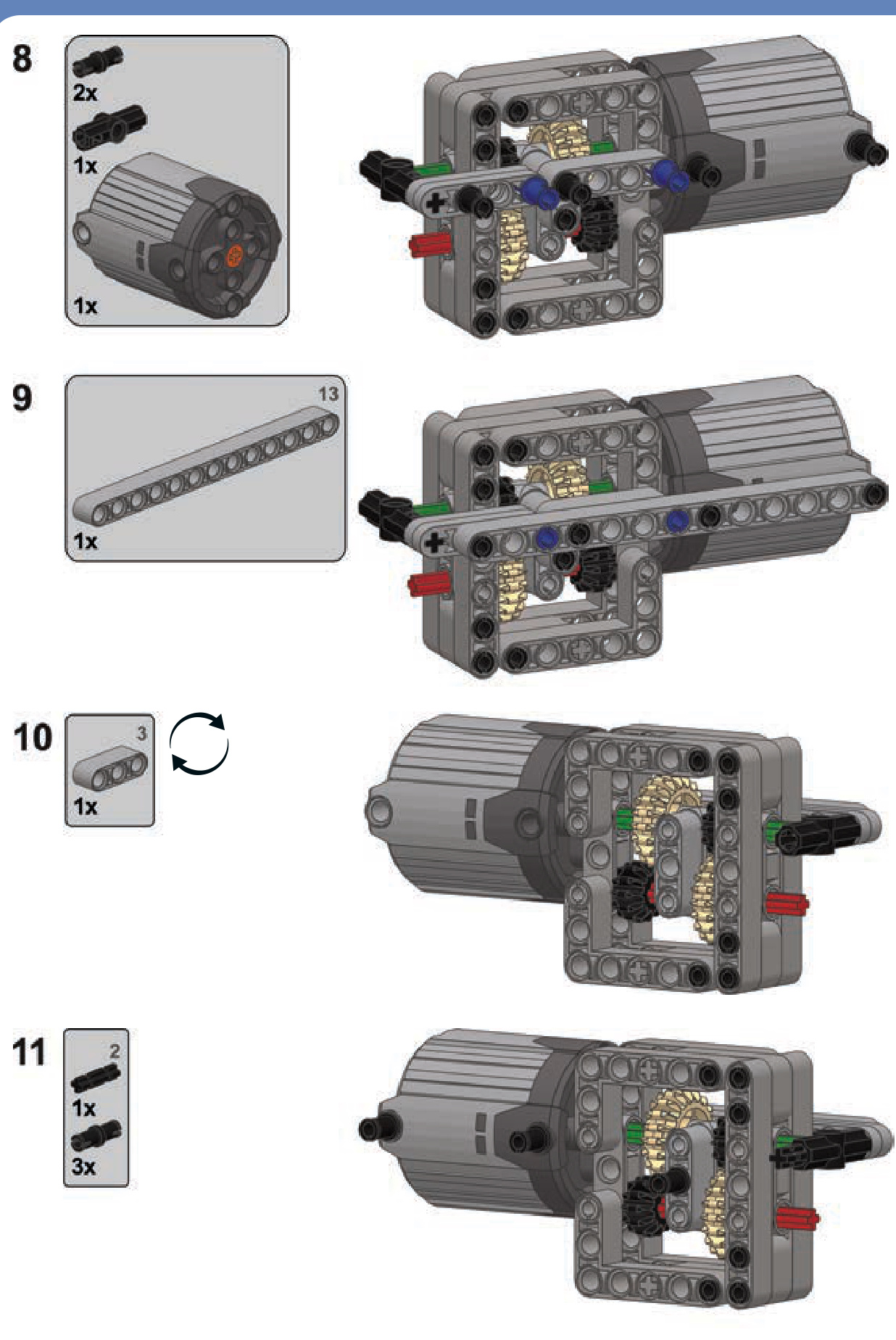
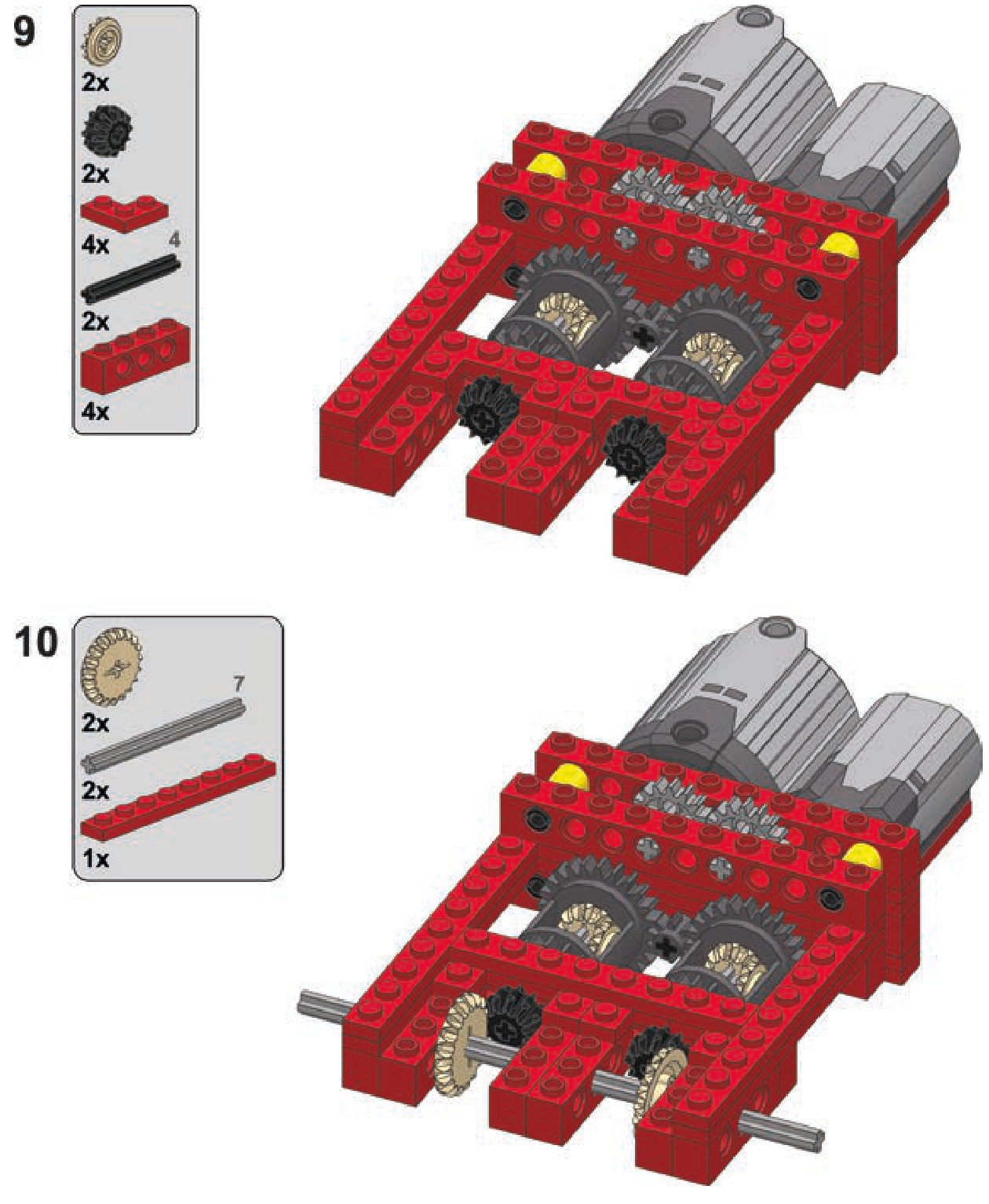
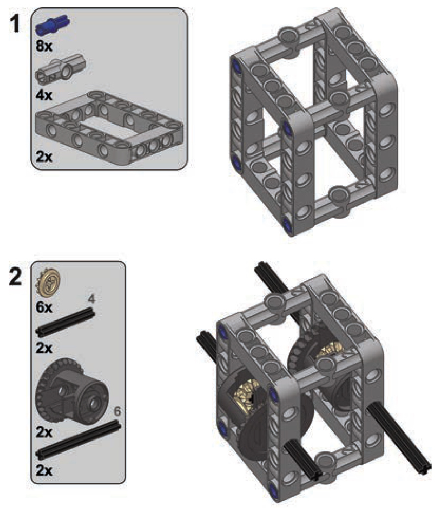
In the example in Figure 16-27, only 1 stud of vertical space inside the hull is taken by the suspension system, but it is taken quite completely. Note that the bars on each side are separate axles—in this case, 7 studs long each. It is possible to use a single axle that traverses the whole hull as long as it’s locked securely in the middle so that twisting one of its ends doesn’t affect the other end.
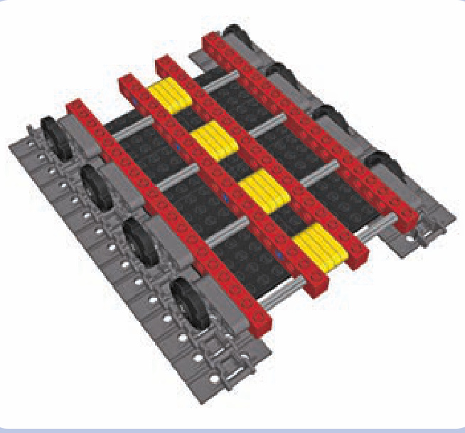
Figure 16-27: A hull floor of a vehicle with torsion-bar suspension
experimenting with road wheels
We can use a pair of wedge belt wheels to create a single road wheel that braces the track from two sides, as shown in Figure 16-29. Wedge belt wheels look more accurate while modeling some tracked vehicles, and they also allow you to build compact suspensions, as shown in Figure 16-30. (LEGO models aren’t heavy enough to effectively compress solid rubber, so the shock absorption effect achieved with these tires alone is minuscule.)
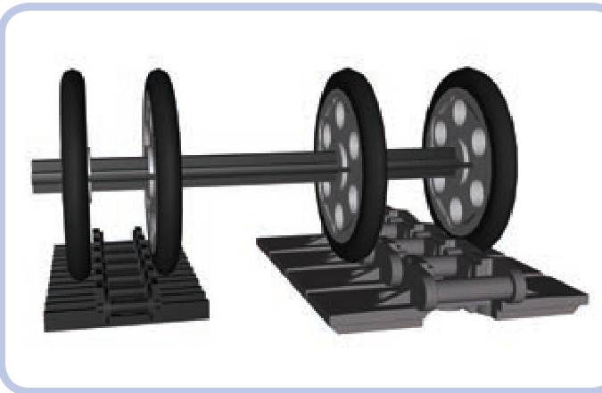
Figure 16-29: A pair of wedge belt wheels 1 stud apart can firmly secure the older type of track. If they are 2 studs apart, they can do the same with the newer type of track.
Early tracked vehicles were built with road wheels of solid metal. Later, engineers observed that vibrations between the tracks and the vehicles could be reduced by putting rubber rims over the road wheels. Today, rubber rims are considered standard for real-life tracked vehicles. Note that these rims are different from conventional tires: They are made of solid rubber, they’re thin, and they have no tread.
There is an easy way to re-create a road wheel with a rubber rim using LEGO pieces so that it looks accurate: You can use a wedge belt wheel with a special solid tire (#70162), as shown in Figure 16-28.
Figure 16-28: A belt wheel with a tire. The tire is solid rubber and very easy to put on and take off.
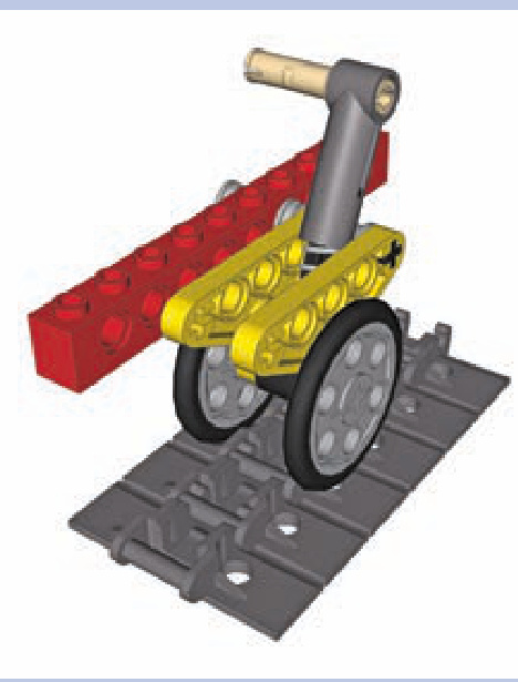
Figure 16-30: This suspension, which uses a trailing arm and a shock absorber, takes advantage of double road wheels to position the absorber as low as possible. With a central road wheel, the shock absorber would have to be moved to the outer side or be located much higher.
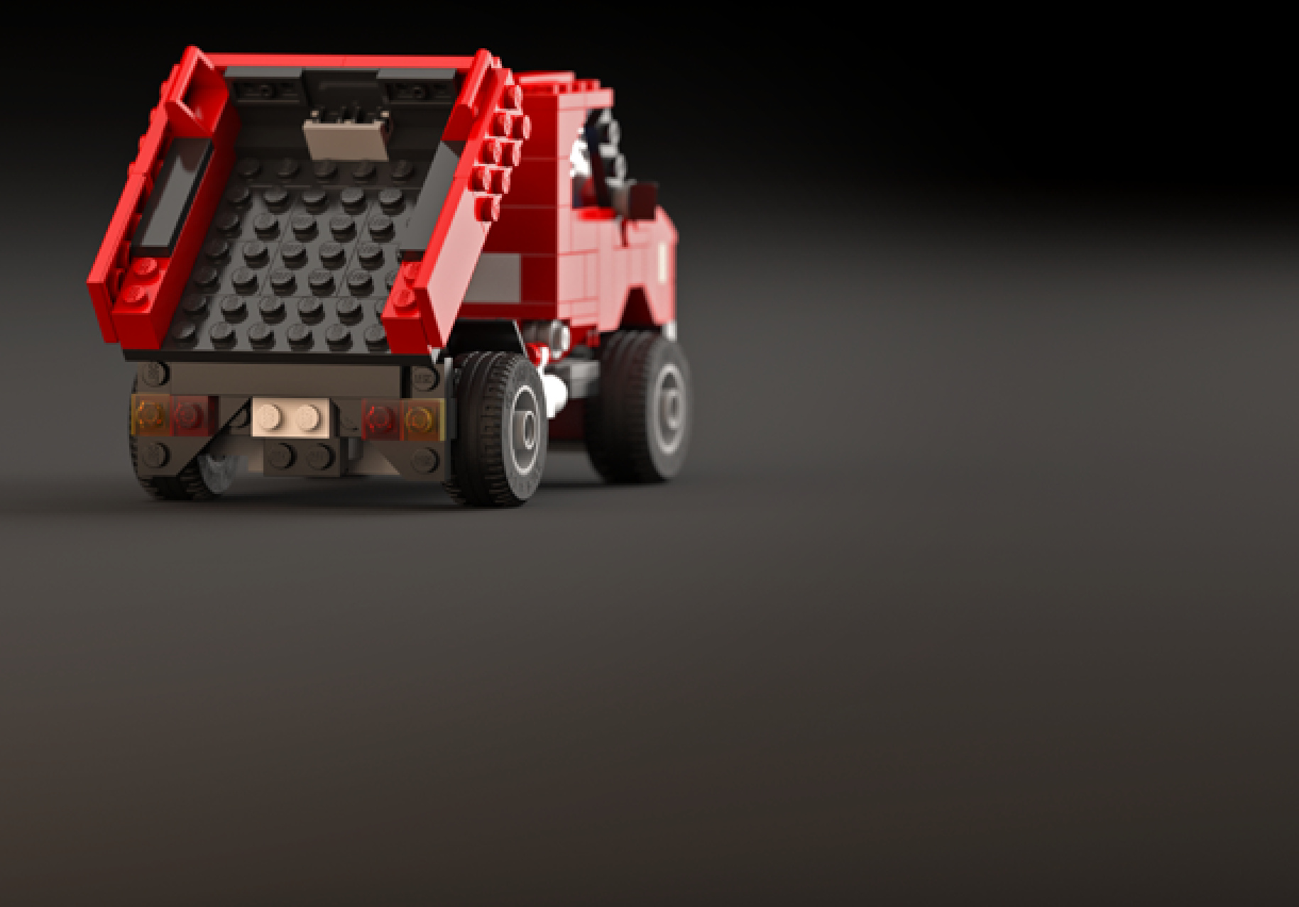
My model of a Soviet T-72M tank, shown in Figure 16-31, employed yet another approach: The wedge belt wheels with tires were simply inserted into the central portion of the track, and they held it in place surprisingly well. At the same time, they were all suspended on torsion bars.
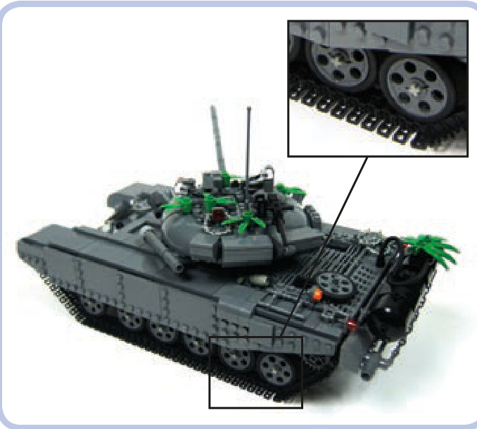
Figure 16-31: A model tank using wedge belt wheels with tires, suspended on torsion bars
Another interesting thing about wedge belt wheels is that without the tire, they have a diameter that perfectly matches that of certain sprocket wheels. They can be used to conceal colorful sprocket wheels for aesthetic effect, as shown in Figures 16-32 through 16-34.
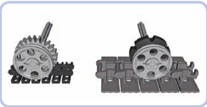
Figure 16-32: The diameter of a wedge belt wheel matches the diameter of a 24-tooth gear meshed with the central protrusion of the older track (left) or the diameter of a smaller sprocket wheel meshed with the central protrusion of the newer track (right). Thus, the wedge belt wheels can be used to conceal the real road wheels and improve aesthetics.
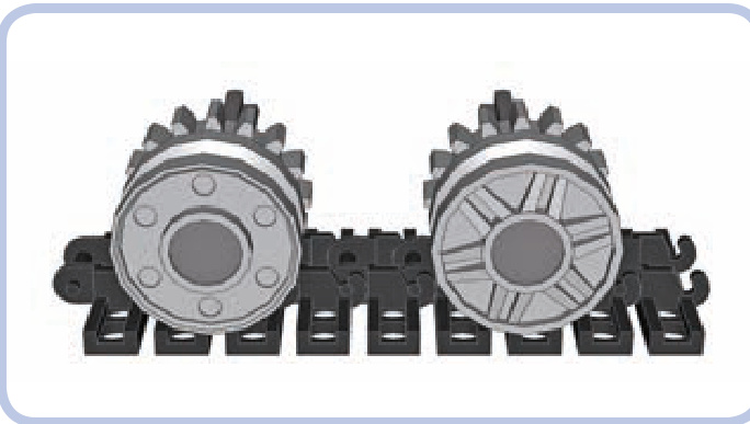
Figure 16-33: Concealing 16-tooth gears behind mm wheels (#56902). As shown here, the two sides of these wheels look different and can be used together to create an interesting aesthetic effect.
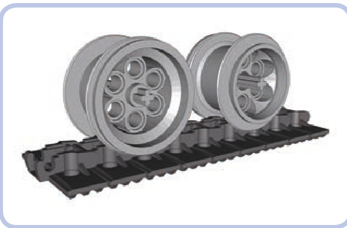
Figure 16-34: The newer type of track works fairly well with VR wheels (#6595). These wheels also have two sides that look different, and their size and appearance make them very suitable for large models.
If you’re curious about how we can power tracked vehicles like tanks and bulldozers, skip to “Subtractors” on page 280, where you’ll learn the methods of steering tracked vehicles and independently driving each track.
17
transmissions
Just like their real-life counterparts, LEGO transmissions are mechanisms capable of changing their internal gear ratio. They can increase gear reduction in the drivetrain when more torque is needed and decrease it when speed is of greater importance. It’s the same principle at play when shifting gears in a car or in a bicycle, and it makes LEGO electric motors much more versatile.
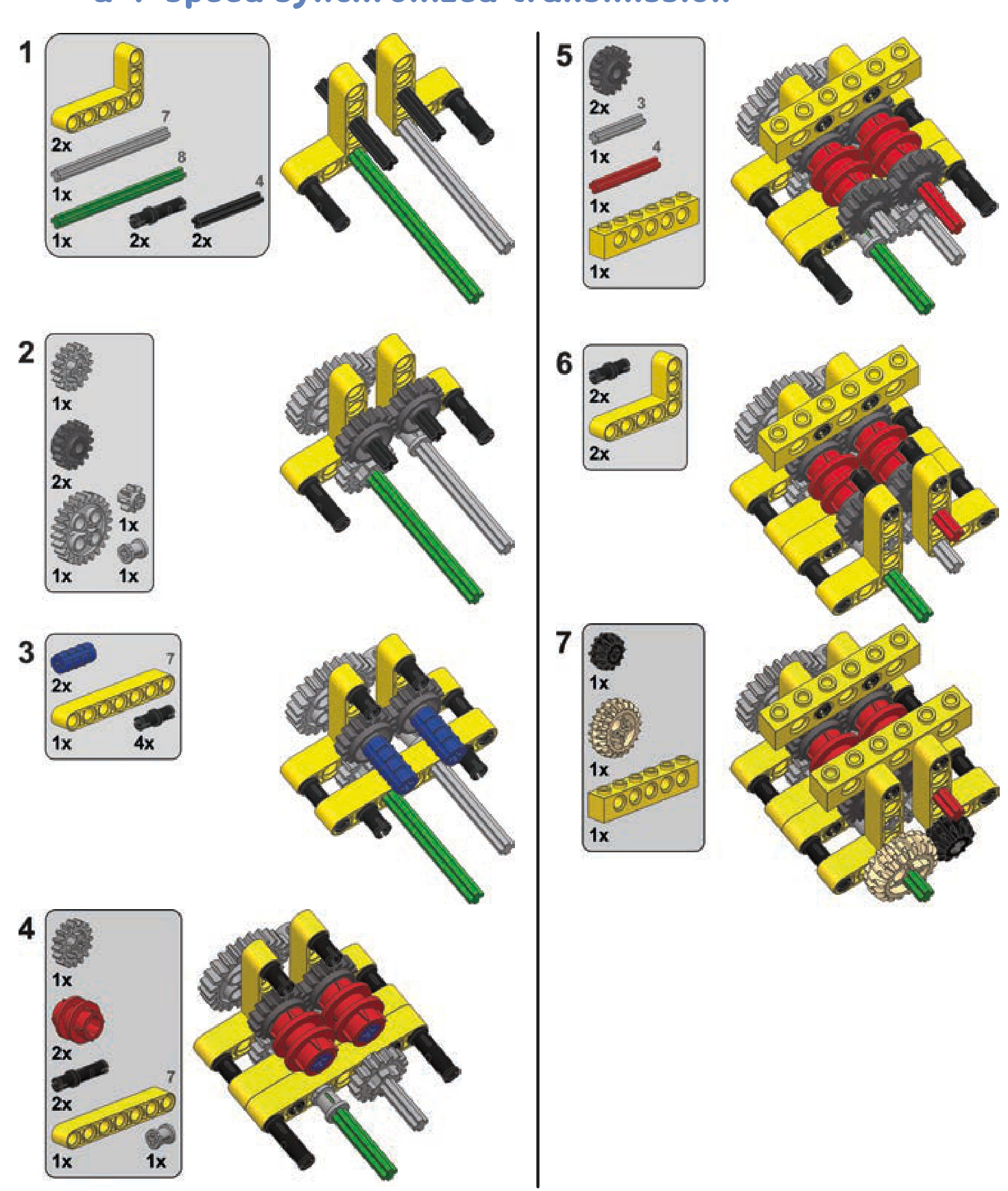
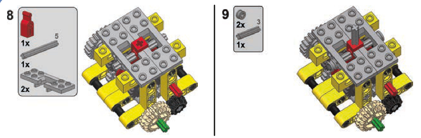
A typical transmission has a number of fixed gear ratios, one of which can be selected at a time. Such a gear ratio is often simply called a speed or a gear: We can shift to lower gear (increasing the gear reduction) or to higher gear (decreasing the gear reduction). Therefore, a transmission must have at least 2 gears (as shown in Figure 17-1), while some of the most complex ones can have more than 10. Depending on their number of gear ratios, we call them 2-speed transmissions, 3-speed transmissions, and so on.
A transmission usually has a single input and a single output; the input is connected to the drive motor, and the output is connected to the final drive (wheels or tracks). A typical transmission also houses a number of gears, and each speed uses only a few of them. In other words, while some of the gears are used to transfer the drive and affect the current gear ratio, other ones just rotate unused. This makes them work like idler gears: driven but idle. In transmissions, they are called dead gears, and the fewer their number, the more efficient the transmission, as they add weight and thereby friction.
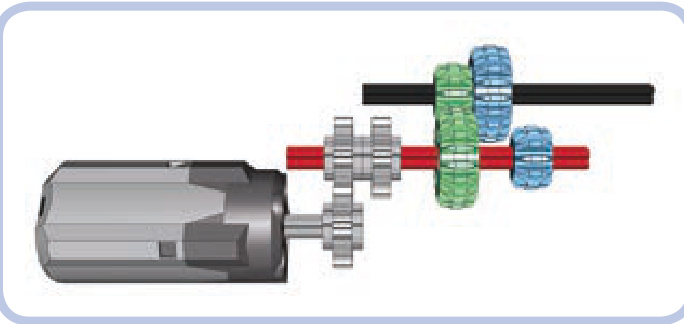
Figure 17-1: The inside of a simple 2-speed transmission. Consider what happens if we move the red axle 1 stud to the left and the green gears disengage and blue gears engage, changing the gear ratio between the motor and the output axle.
Lastly, we’ll consider a special type of transmission called a distribution or split transmission. This type of transmission has one input but several outputs. Such a transmission allows several mechanisms to be driven by a single motor without interfering with each other, as only one mechanism is driven at a time. We will discuss this particular type of transmission at the end of this chapter; for now, let’s focus on the simpler ones.
types of transmissions
When it comes to transmissions, we can organize our models into several disparate categories. Firstly and most importantly, a transmission can be synchronized or non synchronized. This refers to how easy it is to make gears mesh while shifting gears. Whenever a gear is shifted, one pair of gears has to disengage, and another pair has to engage. In synchronized transmissions, these gears can engage at any speed and any position; in nonsynchronized transmissions, engagement is a matter of making their teeth meet properly, which can succeed or fail, depending on the gears’ positions and on the difference of their speeds. If gears fail to engage properly, they grind their teeth, and we have to try to shift the gear again. We can assume that gears will always engage in synchronized transmissions; in nonsynchronized ones, successful shifting is a matter of the shape of the gears’ teeth, the speed of shifting, and a degree of luck. Some types of gears mesh more easily in nonsynchronized transmissions than others. For example, double-bevel gears, because they are beveled, engage more easily than typical
spur gears. Naturally, it’s much easier to shift a nonsynchronized transmission while its input is stopped; in a synchronized transmission, it makes no difference.
Secondly, transmissions can be categorized as sequential or regular. Sequential (or linear) transmissions can only be shifted from one gear to the next closest one. That is, they can be shifted from 2nd to 3rd gear, but they can’t be shifted from 2nd to 4th gear directly; instead, they have to shift from 2nd to 3rd and then to 4th. Regular (or nonlinear) transmissions, on the other hand, are not bound by this restriction, and they often use elaborate shift sticks, like the one in Figure 17-2. They can shift even from 10th to 1st gear directly, even though it may be dangerous to change the gear ratio so much so quickly. In real life, sequential transmissions are common in bicycles and motorbikes, while regular ones are found in cars.
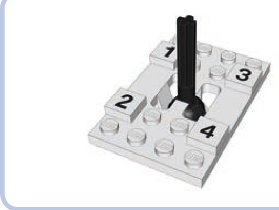
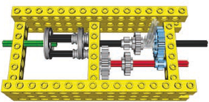
Figure 17-2: The unique shift stick from the 8880 set, the first LEGO set with a nonlinear and synchronized transmission. The transmission has 4 speeds, and the stick can move in an H pattern, allowing it to shift from one gear to any other.
how LEGO transmission driving rings work
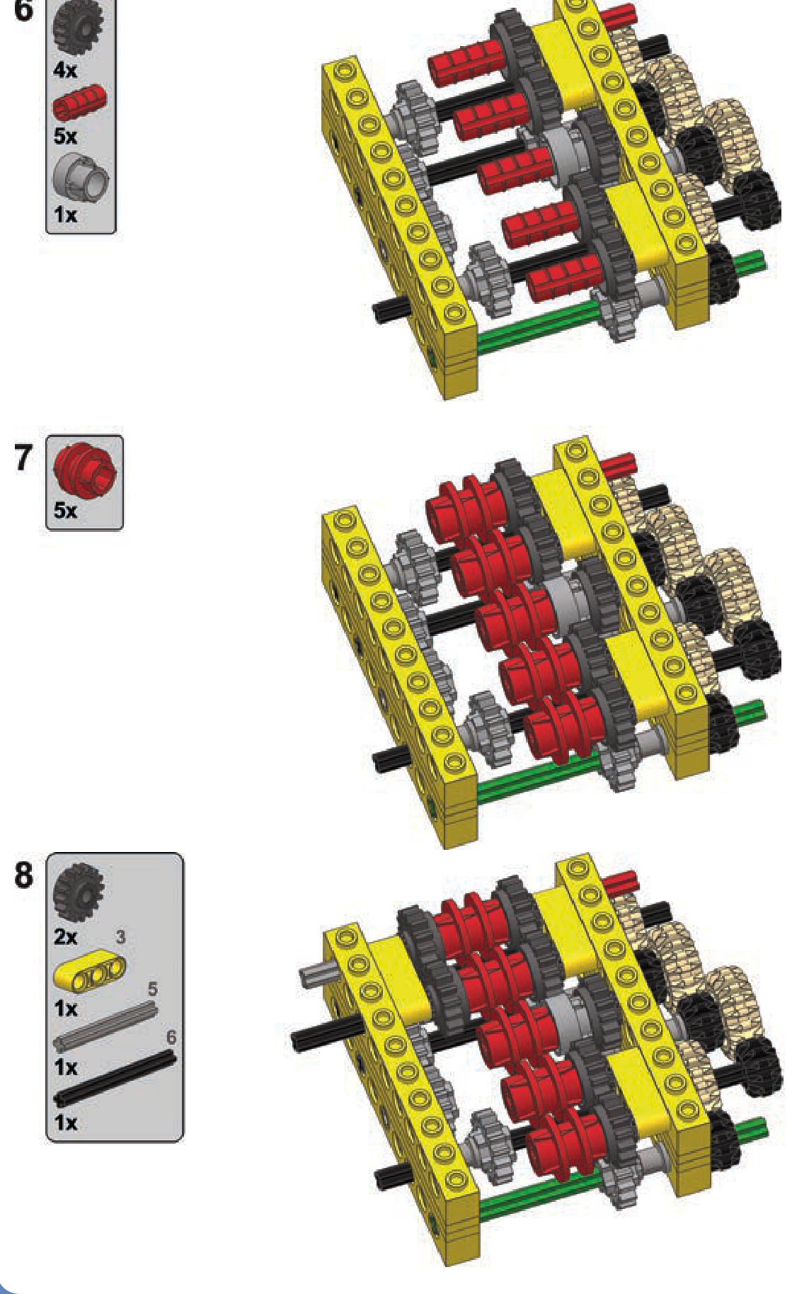
As building a synchronized transmission with regular pieces is quite difficult, LEGO has developed a special piece just for this task. It’s called a transmission driving ring, and it’s shown in Figure 17-3.
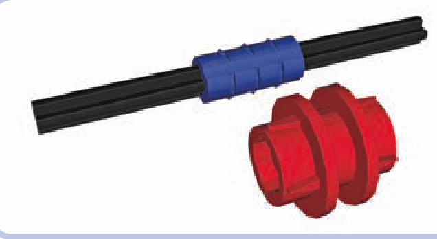
Figure 17-3: The transmission driving ring (red) has to be placed over a ribbed axle joiner (blue). The axle joiner connects two axles, with each of them going 1 stud deep inside it.
The transmission driving ring (red) has to be placed on an axle joiner (blue). This makes the transmission driving ring rotate together with the joiner; at the same time, the ring can slide forward or backward along the joiner. Figure 17-4 shows what happens when we put two 17-tooth gears with clutches on the axle next to the ring. The gears rotate freely on the axle, unless engaged by the driving ring that slides into them.
The easiest way to control the transmission driving ring is to use another special piece called the transmission changeover catch, shown in Figure 17-5. It was developed specifically to move the ring back and forth, engaging and disengaging it with the adjacent gears. It should be located above the ring, on a separate transverse axle.
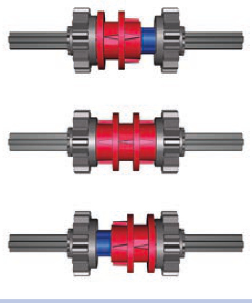
Figure 17-4: There are three positions possible for a transmission driving ring: engaged with left gear, neutral (no gears engaged), and engaged with right gear. Note that only engaged gears rotate together with the axle.
Figure 17-5: The transmission driving ring and the transmission changeover catch. Note that the catch rotates together with the axle it sits on, but it can slide along it freely. Some transmissions make use of this property. To see an animation of this process, visit http://www.technicopedia.com/1994 .html#Parts.
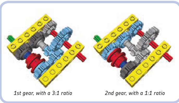
Figure 17-6 shows a very simple 2-speed transmission that uses a driving ring controlled with a catch. If we engage the ring with the gear to its left (shown in the middle), the resulting gear ratio will be 3:1. If we engage the ring with the gear to its right (shown on the bottom), the resulting gear ratio will be 1:1. The key to understanding how this mechanism works is to remember that 17-tooth gears with clutches rotate freely on axles unless engaged with the driving ring. They can therefore be used to transmit drive over the axle they sit on, while not driving that axle or any other gears on it.
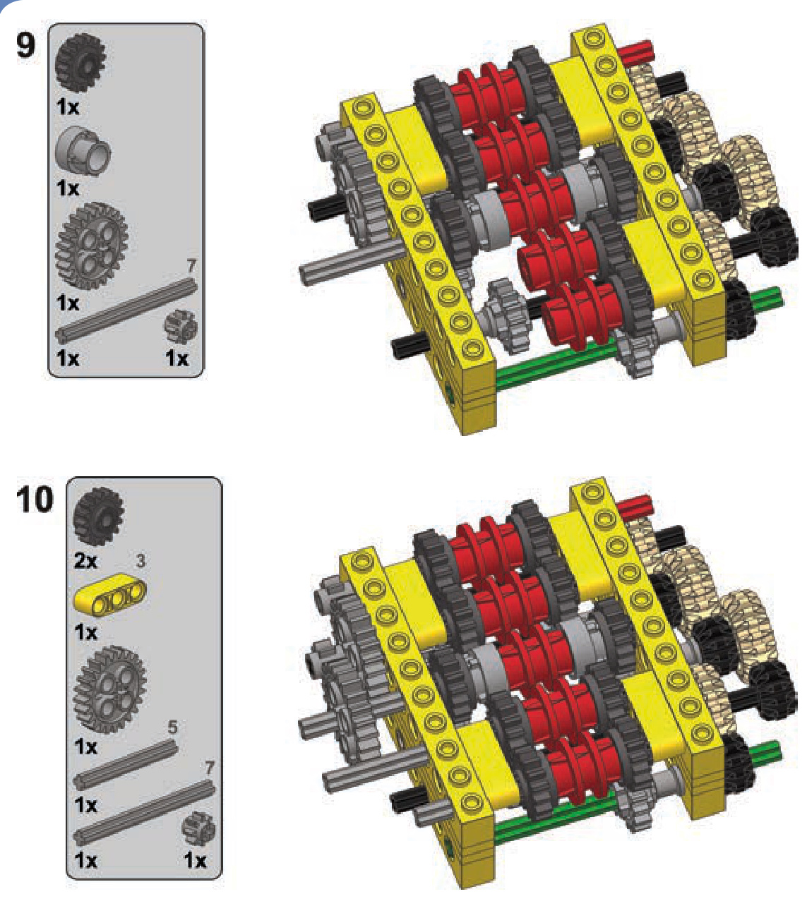
If you like the idea of using synchronized transmissions, you’ll also want to know about a piece called an extension driving ring, shown in Figure 17-7. It works like an overlay for the regular transmission driving ring, allowing it to engage gears 1 stud farther away from it, as shown in Figure 17-8.
The main advantage of the transmission driving ring is that it can engage at any moment, at any speed, without the need to stop the input. The main disadvantage is that it works only with one particular type of gear, so additional gears are needed just to achieve various gear ratios, making plenty of dead gears unavoidable.
Wa rning The transmission driving ring is also a torquesensitive piece; it can disengage itself or even get physically damaged if a large torque is applied to it. This makes nonsynchronized transmissions a more common choice for high-torque applications.
Figure 17-6: A simple 2-speed synchronized gearbox set on neutral gear (top), low gear (middle), and high gear (bottom)
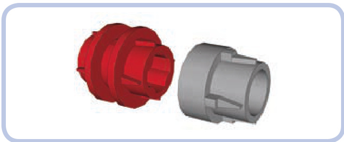
Figure 17-7: The extension driving ring (light grey) can be put over the transmission driving ring (red), extending it by 1 stud. Note that there is a large backlash between the driving ring and the gear it engages through extension.
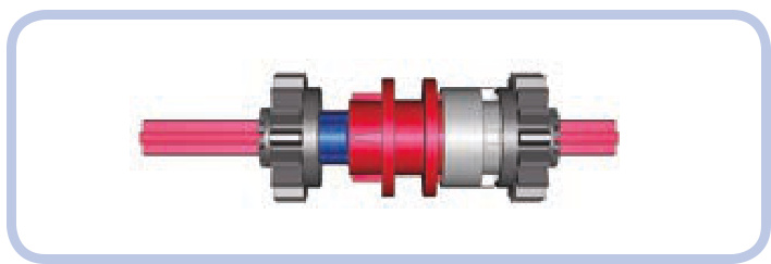
Figure 17-8: The extension driving ring fills the gap between the transmission driving ring and a gear 1 stud away from it, allowing the gear to be engaged.
transmission designs
This section lists a number of designs for complete transmissions. For each design, there is the type of transmission, a short description, and a scheme showing which gears are active at which speed. Building instructions for selected transmissions appear at the end of the chapter.
The following colors are used to mark pieces: green for the input axle, red for the output axle, and light blue for the active gears. The changeover catches are removed for clarity.
Keep in mind that it’s also possible to combine two or more transmissions of any type by making one transmission’s output another one’s input. The number of speeds will be effectively multiplied: For example, a 2-speed transmission combined with a -speed one will produce 8 speeds.
Some builders like to include a reverse gear in their transmissions. This is accurate in relation to real trans mission systems but redundant when used with an electric motor that can be reversed at any moment. I have omitted such designs on purpose because I think they waste a potentially useful speed for no real reason.
Many builders consider a sequential synchronized transmission the best variant of all because it can be easily shifted remotely. While beyond the scope of this book, such a transmission relies on a control mechanism that is independent of the actual transmission and that can be used with many of the designs shown below. For ideas on creating remote-controlled transmissions, check out the website of Sheepo, one of the best transmission builders: http://www .sheepo.es/.
2-speed synchronized transmission
Type: sequential, synchronized
This is the simplest synchronized transmission possible. (Building instructions are on page 261.)
2-speed linear heavy-duty transmission
Type: sequential, nonsynchronized
A transmission designed specifically to handle high torque, shown here with the PF XL motor. Gears are shifted by sliding part of the transmission together with the motor attached to it. This makes the transmission simpler and reduces the number of gears. (Building instructions are on page 262.)
2-speed RC motor transmission
2-speed orbital transmission
Type: sequential, synchronized
This unusual transmission can be built with one or two RC motors. LEGO RC motors have two outputs instead of one, with the outer output having 26 percent more torque and less speed than the inner output. This transmission is connected to both of the motor’s outputs at the same time, allowing us to select from which one it is driven. This allows us to make use of the difference in the outputs’ properties, even though the gear ratio of the transmission itself is 1:1 at both speeds.
Building instructions are on page 264.
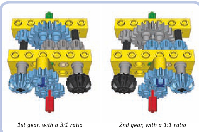
Type: sequential, synchronized
This transmission is placed between two gears and shifted by rotating it 180 degrees. In this example, rotation is done with a dark grey crank that should be blocked once rotated. You can use a worm gear to rotate and then block the transmission. The transmission is synchronized without using the transmission driving ring and provides a vast difference in gear ratios. Additionally, it has no dead gears.
Note the half bushes used to create a gap between the transmission and the bricks on its sides. The gap is intended to prevent the 4L axles on the sides of the transmission from getting into the holes in the bricks and blocking the transmission.
Building instructions are on page 266.
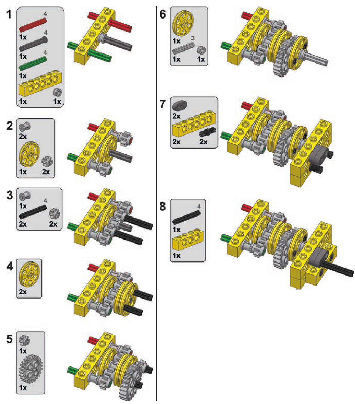
2-speed ratchet transmission
3-speed linear transmission
Type: sequential, synchronized
This transmission uses a ratchet to shift gears. It shifts when the direction of the motor that drives it changes. It’s small, simple, and synchronized without the use of the transmission driving ring. It can handle significant torque, but its output always rotates in the same direction, regardless of its input direction. So when it’s used in a car, it makes the car drive only forward or only backward.
The transmission works like this: The direction of the input tilts the ratchet left or right. A 17-tooth gear on top of the transmission meshes with one of two 12-tooth doublebevel gears when the ratchet is tilted. The 17-tooth gear sits on an axle pin with friction, and the resistance created this way makes the ratchet press hard against the 12-tooth double-bevel gears. The greater torque is handled by the transmission. The greater the resistance on the ratchet, the harder it presses, meshing its top gear more effectively. There is, of course, a limit to how much torque can be handled.
Building instructions are on page 267.
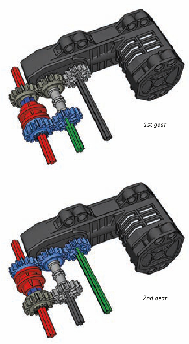
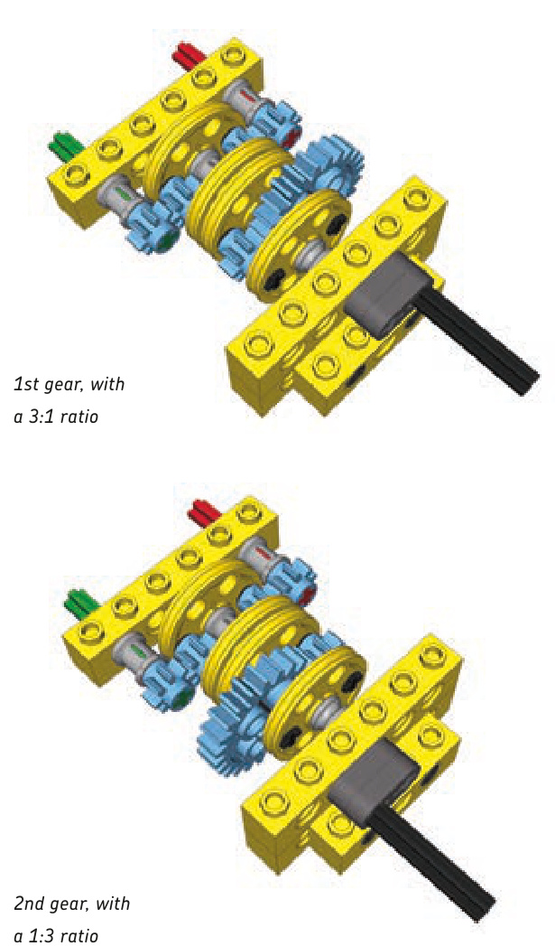
Type: sequential, nonsynchronized
1st gear, with a 3:1 ratio
2nd gear, with a 1:1 ratio
3rd gear, with a 1:3 ratio
This transmission is simple but large. It uses an extendable driveshaft to make the input driven and movable at the same time. The control lever is shown semitransparent for clarity. Building instructions are on page 268.
4-speed double-lever transmission
4-speed synchronized transmission
Type: regular, synchronized
Type: regular, nonsynchronized
This regular transmission is strong and useful. It’s very simple and relatively small, but it has two control levers, which is challenging when it comes to remote control. It consists of three shafts connecting input and output: one fixed and two that can slide by 1 stud. Due to its simplicity, no building instructions are provided, just the schemes of its speeds. The control levers are shown semitransparent for clarity.
Not e The structural parts and the control levers have been removed for clarity.
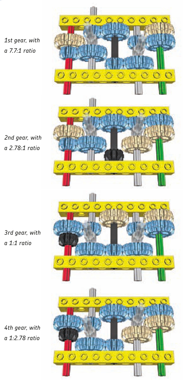
This synchronized transmission, shown in Figures 17-9 to 17-11, has two transmission driving rings, only one of which should be engaged at a time. Relatively small and providing a large difference in gear ratios, it can be controlled by a single lever moving in an H pattern or by two levers, one for each driving ring. It has a lot of dead and idler gears.
Building instructions are on page 270.
5-speed linear transmission
Type: sequential, nonsynchronized
Figure 17-9: The 4-speed synchronized transmission with a single control lever moving in an H pattern. Note the special so-called “changeover plates” (light grey) used to control the shifting lever’s movement and to support the axle it moves along.
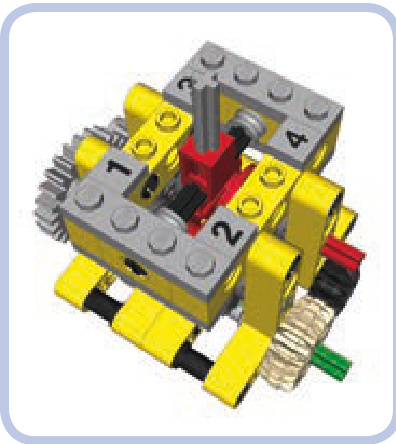
Figure 17-10: The 4-speed synchronized transmission with a single control lever moving in an H pattern. The lever is housed and supported by common LEGO pieces.
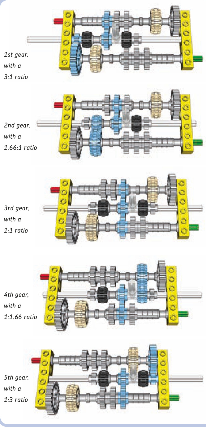
Figure 17-11: The 4-speed synchronized transmission with two control levers, each controlling a single transmission driving ring. Note that both rings can’t be engaged at the same time: One has to be set in neutral position before the other one is engaged.
This transmission has one central shaft that can slide by 4 studs. Its disadvantage is that the central shaft makes use of a rare 16L axle, which can bend and disengage gears under high torque. Due to its simplicity, no building instructions are provided here, just the schemes of its speeds. The control lever is shown semitransparent for clarity.
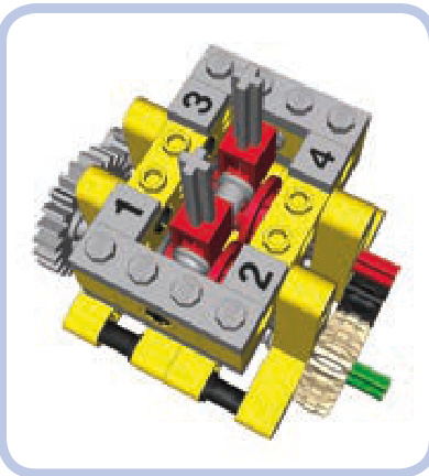
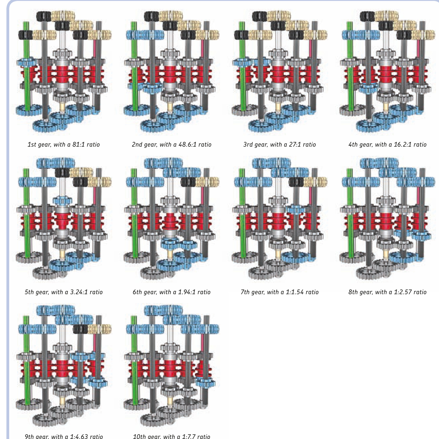
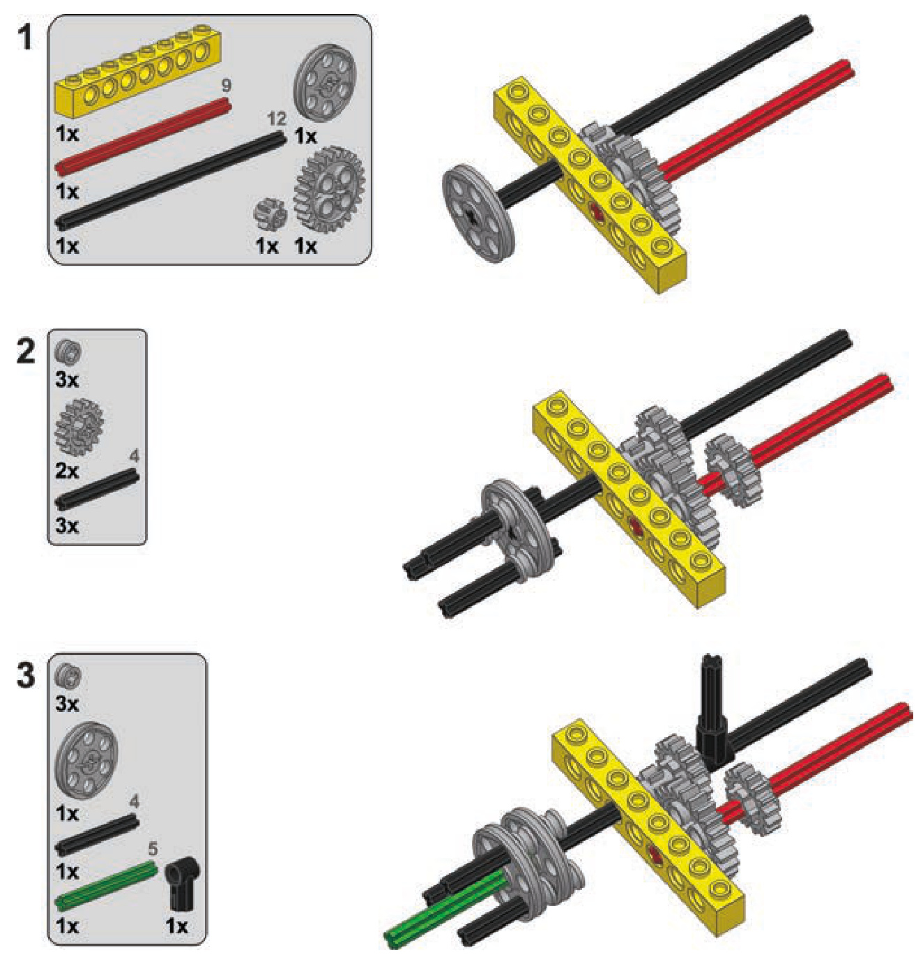
10-speed synchronized transmission
Type: regular, synchronized
Not e This is the bottom view with the structural parts and the control levers removed for clarity.
This transmission has a 4-speed design that’s expanded further with the use of extension transmission driving rings.
If you study it closely, you’ll notice that it can be expanded beyond 10 speeds by adding another pair of extensions and then four regular transmission driving rings. You can continue to expand it beyond this point by again adding two extension driving rings and so on. There’s no limit to how many speeds can be added this way, except that the number of dead gears in the transmission increases quickly and a 14-speed version generates enough resistance to stall a PF XL motor. (Building instructions are on page 271.)
continuously variable transmission
Type: sequential, synchronized
The continuously variable transmission (CVT) is a special type of a transmission. It doesn’t have a definite number of speeds with fixed gear ratios. Instead, it has a minimum and maximum ratio, and it can be shifted continuously between them.
Real-life CVTs are very useful, but at the same time, they are very complex and often based on hydraulics or magnets. The easiest way to build a CVT with LEGO pieces is by using cones and a rubber band.
As you see, the transmission consists of input and output shafts with opposing cones connected by a rubber band. The band can be moved left or right so that it’s wrapped around the broader portion of one cone and the narrower portion of the other. The circumference of the each cone is at its narrowest and at its broadest, which corresponds to a 1:2.27 ratio. This transmission can therefore be shifted smoothly between ratios 1:2.27 and 2.27:1.
The transmission can’t handle much torque, and the tension of the rubber band has to be adjusted carefully in order for it to work properly. Too little tension will make the rubber band slip; too much tension can displace the cones. The original LEGO rubber bands work best as they are sticky and have a round profile; they come in many variants of different lengths that can work better or worse depending on the distance between the shafts in the transmission. Also note that the control lever module is mounted between two bricks with axle holes. Axle holes not only keep the control lever straight. They also add some resistance so that it takes force to move the lever and thus the lever can’t be moved by the rubber band’s tension.
Building instructions are on page 276.
distribution transmissions
One type of transmission’s primary function isn’t to change gear ratios but to change which output is driven at the moment. This transmission, the distribution transmission, can be synchronized or not, depending on whether transmission driving rings are used. Distribution transmissions are very useful whenever there is a need for one motor to control one of many functions at a time, and they are quite popular in LEGO Technic sets.
In most cases, the distribution transmissions themselves are fairly simple; it’s transferring the drive from them to several receiving mechanisms that can be tricky. Figures 17-12 to 17-16 present a few examples of such transmissions with various numbers of outputs, shown without housing for clarity. Note that the examples have a 1:1 ratio on all outputs for simplicity, but it’s possible to create various ratios on various outputs.
Figure 17-12: A nonsynchronized distribution transmission with two outputs
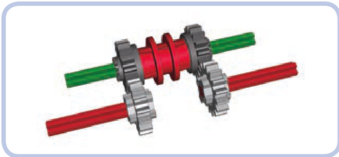
Figure 17-13: A synchronized distribution transmission with two outputs
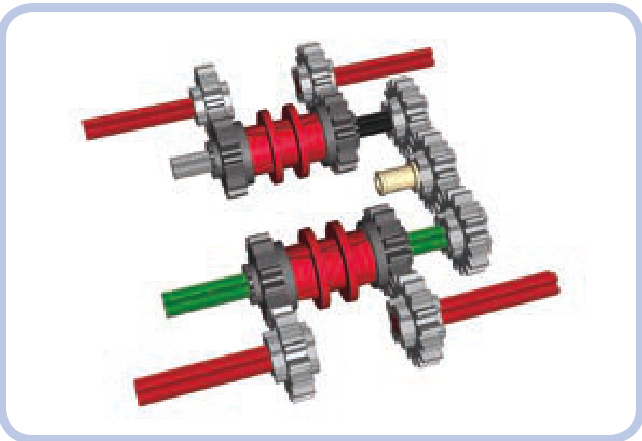
Figure 17-14: A synchronized distribution transmission with four outputs
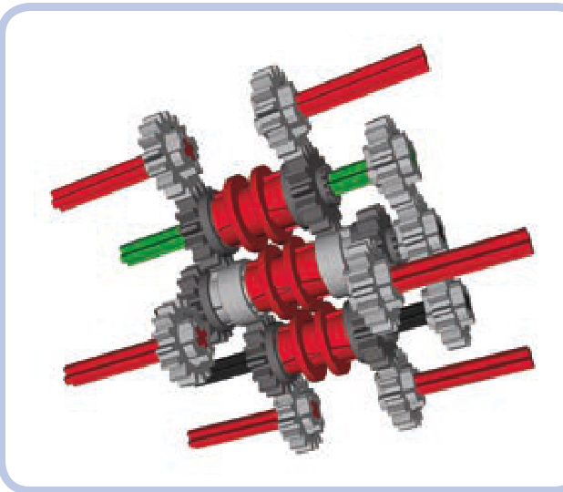
Figure 17-15: A synchronized distribution transmission with six outputs
Figure 17-16: A synchronized distribution transmission with eight outputs
a 2-speed synchronized transmission
a 2-speed linear heavy-duty transmission
a 2-speed RC motor transmission
a 2-speed orbital transmission
a 3-speed linear transmission
a 4-speed synchronized transmission
a 10-speed synchronized transmission
a continuously variable transmission
adders and subtractors
Adders and subtractors are mechanisms used to couple two or more motors together. Coupled motors are usually used to control a single function, most often the propulsion of a vehicle. They can work together (in an adder) or against each other (in a subtractor). Both mechanisms make use of differentials, and both are examples of advanced mechanics. The way subtractors work is particularly fascinating.
You’ll find that using adders is a great way to give your motor even more power. Subtractors will be most useful when building tanks and construction vehicles, as these mechanisms have two outputs perfectly suited for controlling two treads.
hard-coupling
But first, let’s consider a simpler solution to coupling motors, one that forces two motors to run at the same speed. Making such a connection is called hard-coupling (see Figure 18-1).
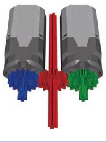
Figure 18-1: Two hard-coupled motors with a single output, shown in red
18
Forcibly slowing or speeding up a motor can be harmful and may permanently degrade its performance. Still, hardcoupling isn’t that different from a LEGO motor’s regular use, where motors are slowed down by a load or sped up by a vehicle rolling downhill. Hard-coupling two or more motors of the same type is a fairly low-risk solution for increasing your model’s power. But what if we want to couple motors of different types or if we find hard-coupling too risky? This is where adders come in.
Not e The performance of identical electric motors can vary, making their speeds differ by a few percent. This is because every motor includes moving parts that are prone to wear, and the precision of the motors’ production process can vary between batches.
coupling motors with adders
Adders couple two motors to work as one; in doing so, adders sum the motors’ individual torques. As a result of this coupling, the output will be the average of the two motors’ rotational speeds. This means that we can use two coupled PF Medium motors in cases where one Medium motor is too weak and an XL motor is too large.
summing torque with an adder
An adder makes use of a differential in order to equalize the differences between two or more inputs and to drive a single output. A differential has three elements that can be used as inputs or outputs: the two axles that come out of it and the case of the differential itself, as shown in Figure 18-2.
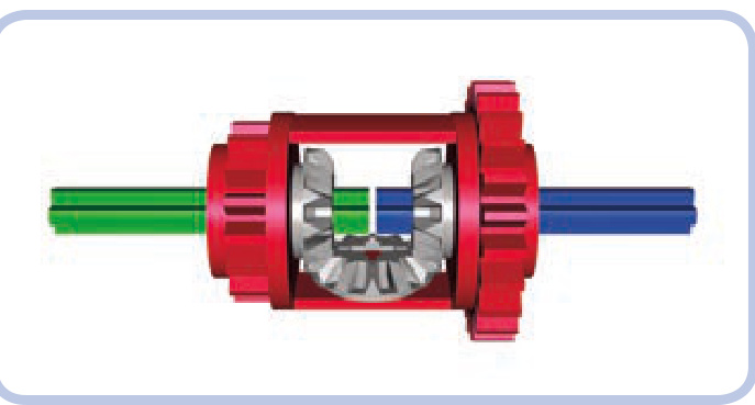
Figure 18-2: A differential that includes two axles (green and blue) and the differential case (red)
A differential consists of a housing with three bevel gears inside, two of which are set on two axles that enter it from opposite sides. The third gear is connected to the housing only. The first two gears are called spider gears or side gears, and the gear fixed to the housing is called a planet gear.
When a differential is used to couple motors, any difference between inputs will be equalized by the system of the differential’s inner gears. The output will be driven by the sum of the inputs’ torques and the average of their speeds. Figures 18-3 through 18-6 show some examples of two motors coupled with an adder in various ways. The biggest distinction among these variations is the use of different differentials. The motors’ inputs are blue and green, and the adder’s output is red.
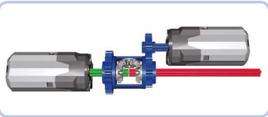
Figure 18-3: Two PF Medium motors are driving the differential case (blue) and one of the axles (green). The other axle (red) is the output.
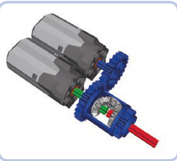
Figure 18-4: The same setup as in Figure 18-3 but with the motors placed side by side
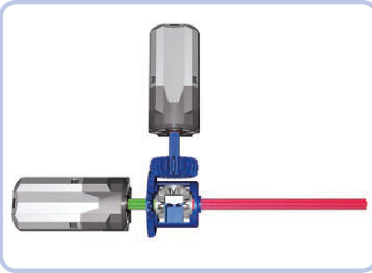
Figure 18-5: An adder using the latest differential variant
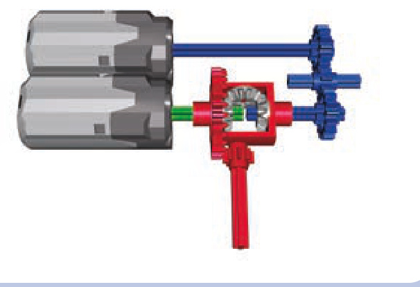
Figure 18-6: An adder using the oldest differential variant
Not e When using adders, always try to have similar gear ratios between the motors and the adder. Differences in gear ratios will make the motors share the load unevenly, with one motor working harder than the other. The gear ratio immediately after the adder (that is, between the adder and the mechanism it drives) does not affect the load distribution.
You already know that an adder sums the torques of its inputs and averages their speeds, but let’s express these relationships mathematically. If we have one motor, , and another motor, motor , then the adder’s torque is equal to
and if is the total number of motors, the adder’s speed is equal to
speed(motor1) + speed(motor2)… + speed(motorn )
One important consideration when building adders is the direction each input rotates. Coupled motors are usually powered from the same source, resulting in an identical direction of rotation. But depending on whether the inputs’ directions match, the two motors can work together or against each other. The latter case is obviously undesirable, as it results in decreased torque and speed.
All the examples shown above have motors running in the same direction; however, in some cases, it’s convenient to have the motors oriented so that they run in opposite directions. For the adder to work properly in such a case, we need to reverse the direction of one motor, either by powering it from a power source with the opposite polarity or by connecting it to a shared power source through a switch (shown in Figure 18-7). With older 9V motors, you can reverse the polarity of a motor by simply rotating its wire connector 90 degrees.
Figure 18-8 shows two examples of adders that need one of their motors reversed.
Figure 18-7: A Power Functions switch (left) and a 9V system switch (right)
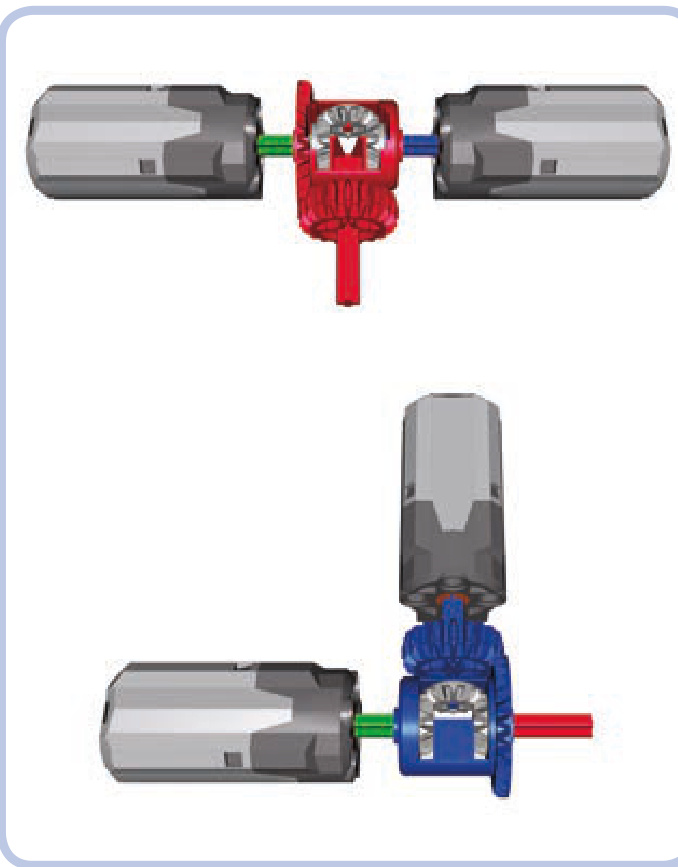
Figure 18-8: These two adders won’t work properly unless we change one motor’s rotational direction.
adding more than two motors
In most cases, coupling two motors will give us enough torque, but what if we want even more torque? We can use an adder to couple more than two motors, but unfortunately the mechanism’s size and complexity will increase drama tically since every motor beyond two requires one more differential (see Figure 18-9).
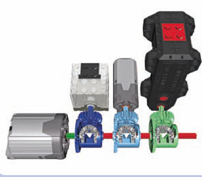
Figure 18-9: It takes three differentials to couple four motors in this chain of adders.
Each differential other than the first one has one input already taken, as it’s connected to the previous differential (the second differential is connected to the first one, the third to the second one, and so on). Thus, we are left with only one free input, and we can add only one motor for each differential. Unfortunately, the resulting high torque makes chaining adders in this way fairly risky.
When more than two motors need to be coupled, it’s usually a better choice to use motors of the same type and hard-couple them. This is true not only because it takes less space but also because with more motors, there is more torque to transfer, and differentials are not fit for handling high torque. Hard-coupling with knobs (shown in Figure 18-10) is a reasonable alternative.
Figure 18-10: These four motors are hard-coupled with knobs, making them more torque resistant than differentials.
subtractors
Subtractors combine the power of two motors in a more complex way. Each subtractor has two inputs and two outputs and also uses two differentials. Rotating one input of a subtractor makes both outputs rotate in the same direction; rotating the other input makes the outputs rotate in opposite directions. Both inputs can be rotated at once, making the outputs rotate at different speeds.
It’s easier to understand how a subtractor works when thinking of its most common use: driving tracked vehicles. A typical tracked vehicle has two tracks: left and right, as shown in Figure 18-11. When both tracks rotate in the same direction, the vehicle moves forward or backward along a straight line. When the tracks rotate in opposite directions, the vehicle turns in place. When the tracks rotate at different speeds, the vehicle makes a wide turn, as a car would, and the greater the difference between motor speeds, the tighter the turn.
Figure 18-11: A simple tracked vehicle
With tracked vehicles, we can assume that one of the subtractor’s input motors is for driving and the other is for turning. Let’s call them and respectively, and note that is usually faster than If only is running, both tracks (that is, both outputs) rotate in the same direction, making the vehicle drive straight. If only is rotating, both tracks rotate in opposite directions, making the vehicle turn in place. Now, an interesting thing happens when both and are running at the same time: One track rotates at speed, and the other at speed. Depending on how much these speeds differ, each track can rotate very slowly , stop completely , or rotate in the opposite direction . Figure 18-12 shows how and affect the motion of a vehicle.
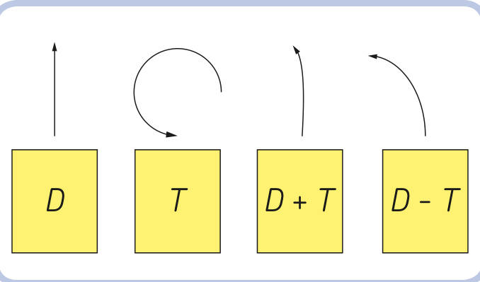
Figure 18-12: The path of a tracked vehicle with subtractors’ inputs being driven. D represents the driving motor (faster), and T represents the turning motor (slower).
By adjusting our inputs’ speeds, we can achieve any combination of the tracks’ speeds: Each track can be stopped or can rotate forward or backward at a speed ranging from almost zero to the sum of the speeds of both inputs.
Note that the relationship between the motors’ maximum speeds affects the way the subtractor works. As an example, let’s imagine we have a vehicle driving straight at full speed and we start turning at full speed. There are three possibilities:
If the speed of is greater than that of neither track will be stopped or reversed; one track will slow down, and the other will accelerate. The vehicle will start turning along an arc while continuing to drive in the same direction. If the speed of is equal to that of one track will stop, and the other will accelerate; the vehicle will start turning almost in place, with the stopped track being the center of the turn.
If the speed of is less than that of one track will be reversed, and the other will accelerate; the vehicle will start turning almost in place, with the center of the turn located between the tracks at a point proportional to their speeds (closer to the slower track, farther from the faster one).
The difference between the maximum speeds of and is a crucial consideration when selecting motors and gear ratios to drive the subtractor. Usually, the first of the three cases listed above (with the faster drive motor and the slower steering motor) is the most realistic and convenient case: A vehicle that goes straight faster than it turns is easy to control and behaves real tracked vehicles do.
Also, the turning input’s speed is very important when a vehicle is turning in place. The tracks rotate in different directions, so the difference between the two tracks’ speeds is equal to twice the turning input’s speed. Applying too much turning speed will make our vehicle look like a carousel rather than, say, a tank. Additionally, turning in place involves significant friction, as the tracks scrub the ground over a large area. Therefore, it’s a good idea to use gear reduction on the turning input, sacrificing speed for torque.
why use a subtractor?
As you might imagine, a tracked vehicle can be driven with two separate motors as well: one motor driving the left track and the other driving the right track. Using a subtractor takes two motors, too, but has several advantages:
better control A vehicle with a subtractor can drive in a perfectly straight line, while a vehicle with two separate motors is sensitive to differences between the motors’ speeds and to its own weight distribution, which can weigh down the motors unevenly.
lower power consumption In a subtractor, one motor is for driving, and the other is for turning; therefore, we can use two different types of motors together. Driving, tracks separately, on the other hand, requires two identical motors, and two strong motors have a higher total power consumption than one strong motor and one weak one.
more mechanisms Connecting another mechanism (a replica piston engine or a rotating fan in the engine bay, for example) to the drivetrain is easy with a subtractor, as it has one motor used specifically to drive. When two separate motors are used, connecting a mechanism to both of them is impossible, and connecting a second function to one motor can slow it down, resulting in a mismatch in speed.
better remote control Without a subtractor, you need the Power Functions remote with speed control dials to make the vehicle turn in an arc. The regular Power Functions remote will only be able to make the vehicle drive straight or turn in place.
The advantages of a subtractor are somewhat diminished if you have the Power Functions remote control with speed dials, which enables a driver to control the speed of each track independently. There are also some disadvantages to subtractors that should be taken into account at all times. First, a subtractor is relatively large and complex, requires plenty of parts, and adds to the vehicle’s weight. Second, a subtractor relies on differentials, which can be damaged by high torque. My experience shows that using a subtractor to drive a vehicle heavier than involves a serious risk of breaking the bevel gears inside the differentials, regardless of the gear ratio between the subtractor and the sprocket wheels. The other disadvantage to subtractors is that they don’t give you the power benefit of having two drive motors.
longitudinal subtractor
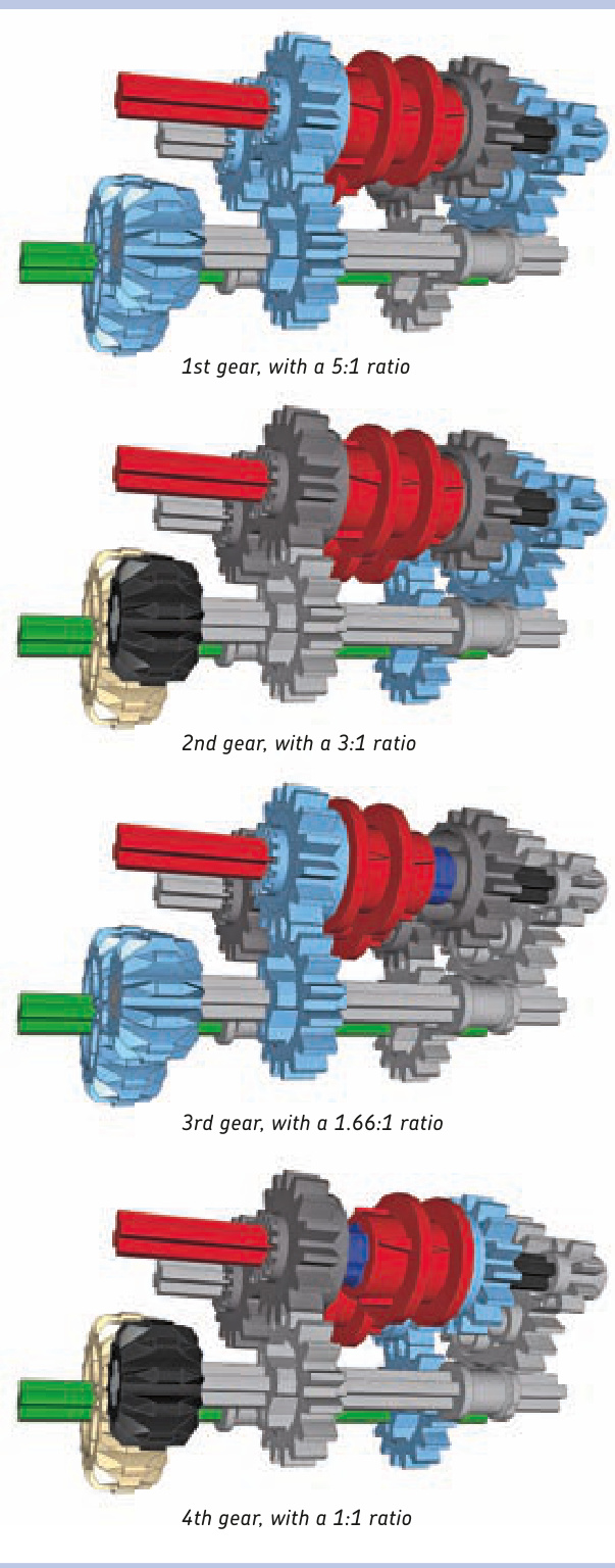
A longitudinal subtractor’s elongated, narrow shape makes it a good choice for tracked vehicles that have long, narrow hulls between their tracks. Figure 18-13 shows the driving input in blue, the steering input in green, the outputs in red, and the sprocket wheels driving the tracks in yellow.
Notice that each motor drives both differentials at once. The PF XL motor drives with a 1:1 gear ratio. The PF Medium motor turns with a 9:1 gear ratio. That ratio makes the turning input’s speed slower than the driving input’s speed, even though the Medium motor’s rotational speed is faster than the XL’s. The driving input rotates at 146 rpm (the normal speed of the XL motor), and the turning input rotates at 30.6 RPM (that is, the speed of the Medium motor reduced by a factor of 9).
Obviously, a subtractor can work with different combinations of motors and gear ratios; the one shown here exemplifies this and is the most efficient combination for most uses. If you use the right gear ratio at the sprocket wheel, you can easily use a single XL motor to drive a vehicle. However, a vehicle’s efficiency at heavier weights depends greatly on the type of surface the model is driving on. To achieve more power for heavier vehicles, you can connect more than a single motor to the driving input, for example, by using an adder.
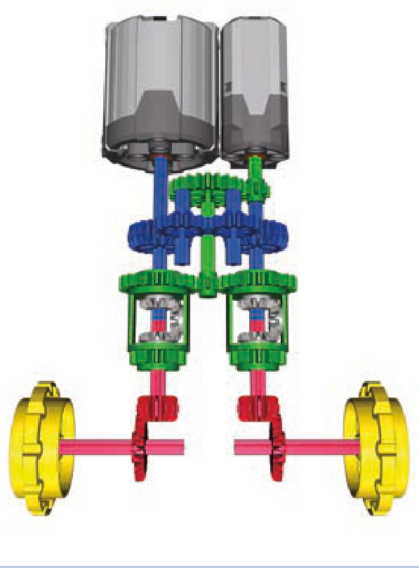
Figure 18-13: A longitudinal subtractor
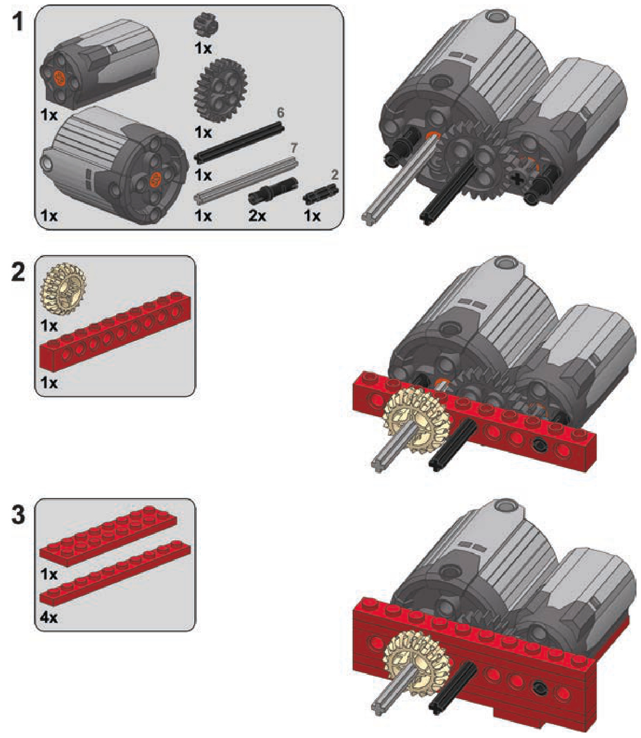
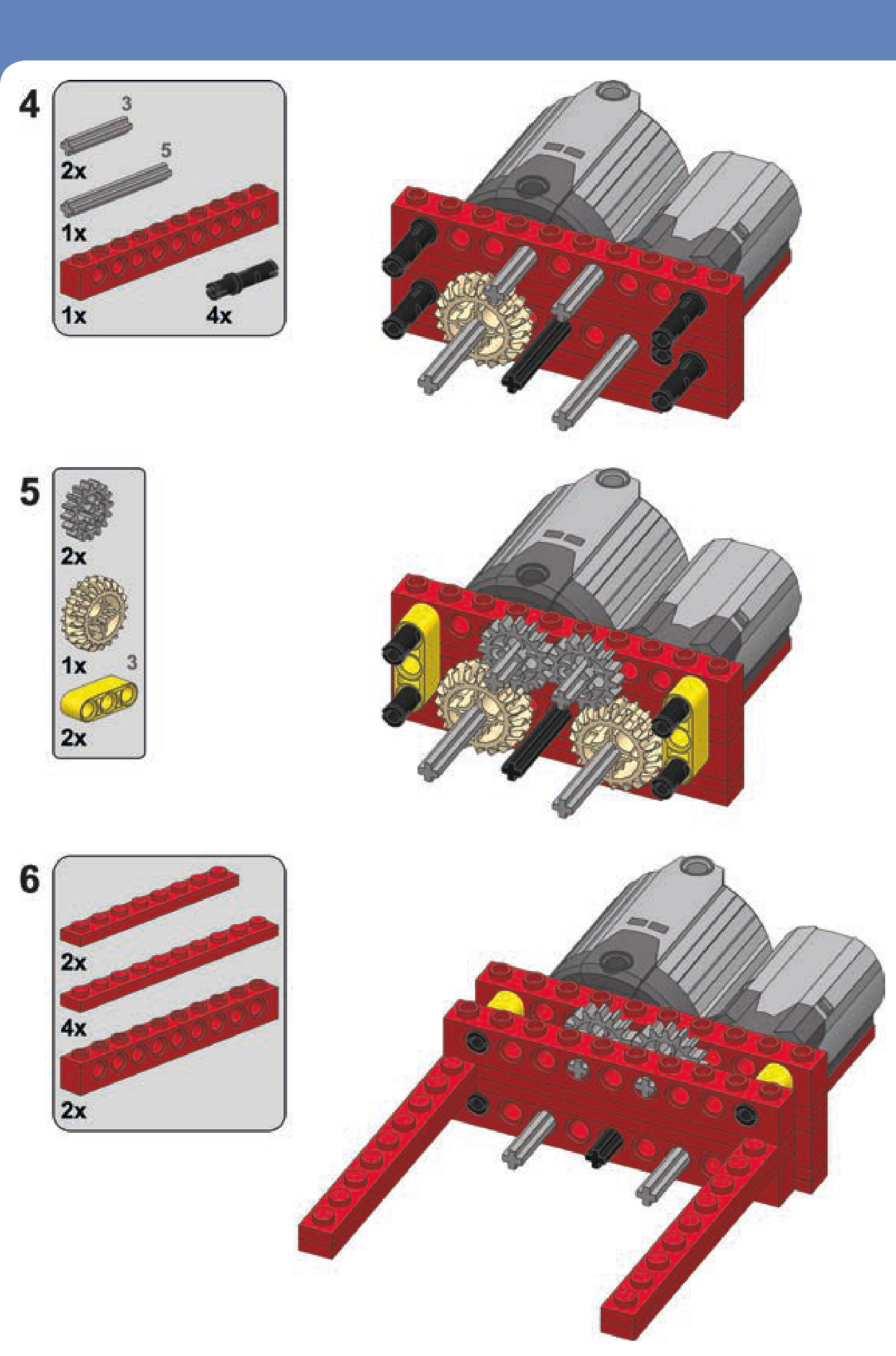
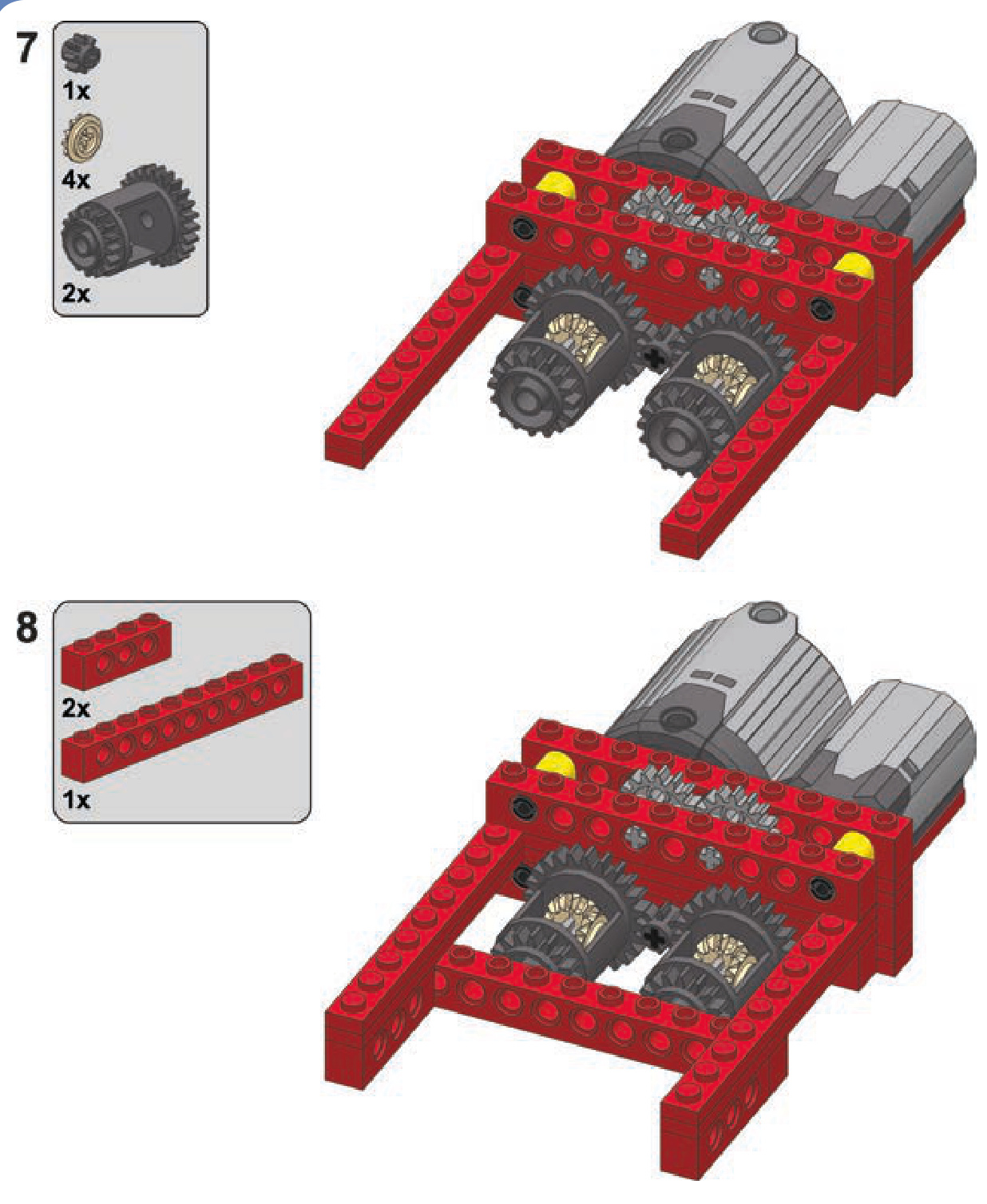
The following are instructions for building this subtrac tor inside a studfull structure. Note that many details can be changed as needed, including the types and number of motors and the gear ratio of the inputs and outputs. You’ll want to replace the bevel gears on the outputs with knobs if you’re building a heavy vehicle.
a longitudinal subtractor
transverse subtractor
This subtractor is smaller and a little less complex than the longitudinal one. Figure 18-14 shows an example of this subtractor with two outputs (shown in red), the driving input (blue), and the turning input (green). Note that we can use the outputs coming from the other differential just as well, and it will work, but the inputs’ roles will be swapped: The turning input will become the driving input, and the driving input will become the turning input.
The transverse subtractor differs from the longitudinal version in several ways. Each motor drives a single differen tial, and two sets of gears connect the two differentials. One set has an even number of gears, and the other an
odd number. The important thing is that both sets have a 1:1 ratio. Therefore, when using this subtractor with two different motors, it’s crucial to make sure that the stronger motor doesn’t drive the weaker one—a gear reduction at the weaker motor should prevent this.
This configuration offers more room for experimen tation than the longitudinal subtractor does. For instance, we can relocate the motors if we drive the differentials with worm gears, preventing the problem of one motor driving another, as shown in Figure 18-15.
Finally, it is possible to build a fully studless variant of this subtractor using the new 28-tooth differentials (see Figure 18-16). It looks very different, but it works just the same.
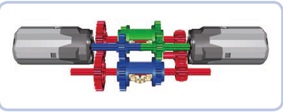
Figure 18-14: A transverse subtractor
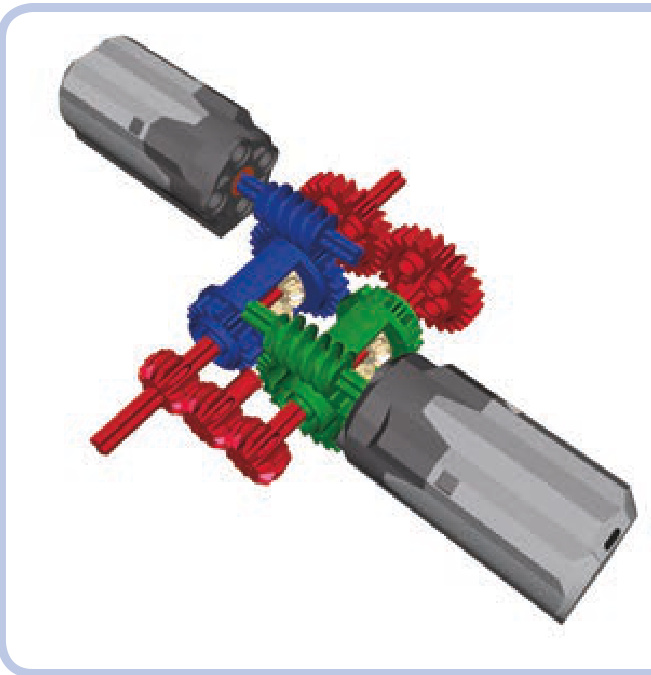
Figure 18-15: A transverse subtractor with worm gears
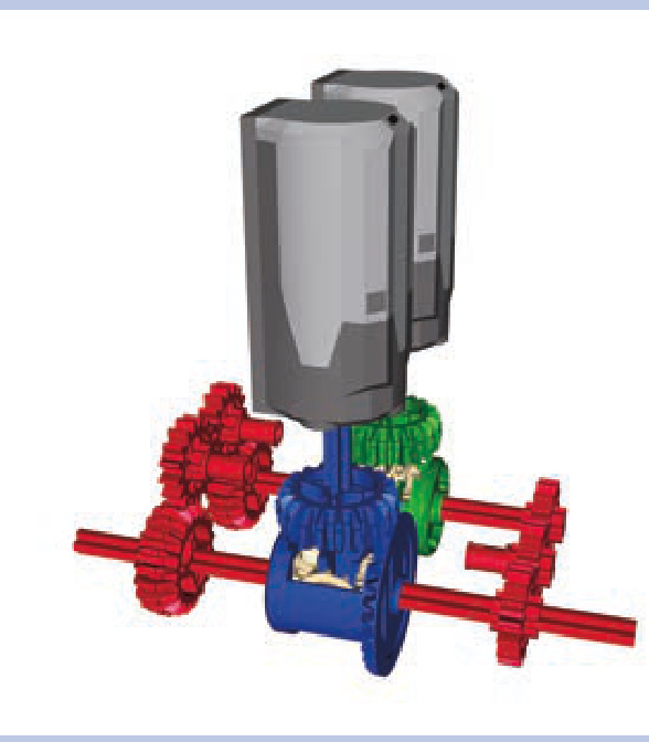
Figure 18-16: A transverse subtractor with the latest differential variants
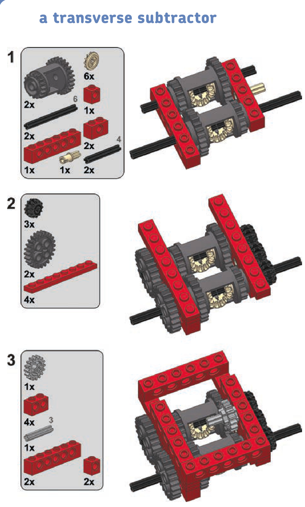
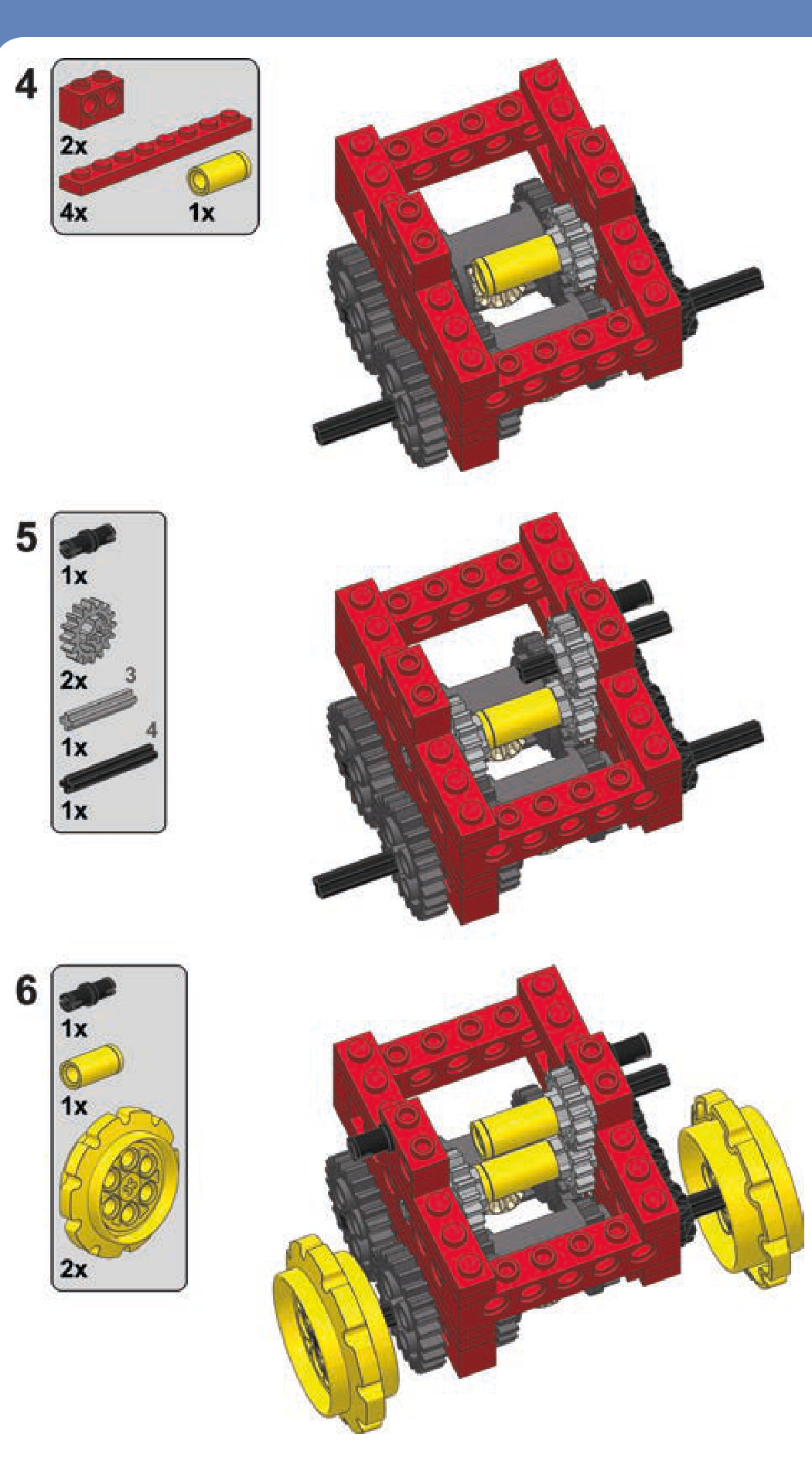
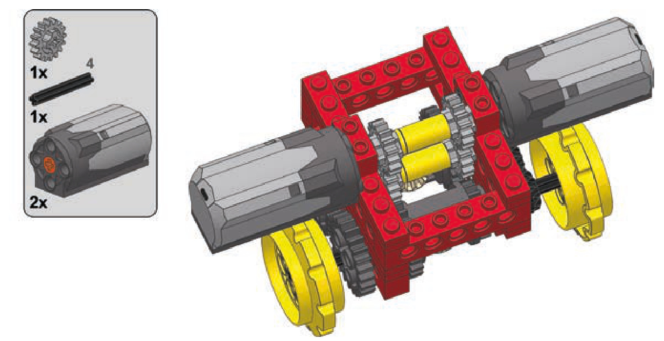
a studless transverse subtractor

19
Builders are usually inspired to create their own models for two reasons: the desire to model a real-life object (like a favorite car or truck) or the desire to model a real-life mechanism or function (for example, a drive or a pneumatic system). If you’re inspired by mechanisms, just look for models that could include one. When you decide to build a model, you’ll want to start by asking yourself three questions:
- Can I make it work well?
- Can I make it look good?
- Can I find sufficient reference material to accurately model this object?
Finding a balance between the aesthetics and functionality of the model is an extremely sensitive task, and it often helps to decide which is more important to you before you start building. As you build and rebuild your models, you’ll likely reexamine your priorities. It’s best to accept one of two options before you even start building: I can compromise the
form vs. function
look in favor of functionality, or I can compromise functionality in favor of the look.
Looking at the silhouette of the object you want to model may also help in the early stages. Bear in mind that most LEGO pieces fit well within straight lines, right angles, and rectangular shapes. This makes trucks much easier to build than motorbikes, for example. You can, of course, use flexible axles and Technic panels to model curved, flowing shapes, but the resulting aesthetic is generally poorly received outside the Technic community and sometimes within it, as well.
cars
Your typical car is challenging to model because of the limited space it provides for electric and mechanical components (see Figure 19-1). Big elements, such as power supplies, IR receivers, and motors, are difficult to incorporate into a car.
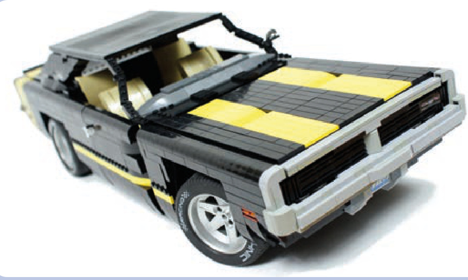
Figure 19-1: My 1969 Dodge Charger model appears to have a massive hood with plenty of space beneath it. However, since I decided to model the car’s huge engine, almost none of this space was available for mechanical components, and I was barely able to fit a mechanism to lift the distinctive grille that reveals the car’s headlamps. Most of the electric components ended up in the trunk.
In most cases, the only spaces available for those elements are the cabin floor, the central space between the seats, the trunk, and the space normally taken by the engine (if you choose not to include a replica of the engine in your MOC). You can also build a motor-free model, with all the functions activated manually, in the spirit of many LEGO sets.
Space constraints become even more challenging with sports cars, which are slung low to the ground and often have open tops, exposing any mechanism installed in the cabin. Cars of this type often use wide tires and independent suspensions, which can result in width issues if you decide to include both in your model. Finally, as sports cars’ engines are particularly huge, choosing between a front-engine and central-engine car greatly affects the amount of space available in the front and in the rear, as well as the silhouette of the model. Figure 19-2 shows an extreme example of this, comparing a front-engine Dodge Viper and a rear-engine Pagani Zonda. Note how the silhouettes of the cars differ— the Viper’s cabin is moved far back, adjacent to the rear wheels, while the Zonda’s cabin starts just behind the front wheels. Both cars, although similar in many respects, offer different challenges and opportunities to a model builder.
Off-road cars, such as SUVs, have taller silhouettes and offer more space, especially in the chassis, but they also have more complex and space-consuming drivetrains and suspension systems. Their engines are usually under the hood, as in the Jeep Wrangler Rubicon shown in Figure 19-3. And many SUVs have hard-top bodies, making it possible to use some of the cabin’s internal space (but also making the car more top-heavy).
Finally, there are cars such as buggies and truggies, whose bodies are built primarily with pipes and whose internal elements are exposed, as shown in Figure 19-4. There are many ways to install elements of the Power Functions system, such as motors and battery boxes, in these cars so as to mimic the original cars’ fuel tanks and other parts.
trucks
Trucks have many qualities that make them easy to model, and they are one of the favorite themes of model builders. They are technically simple to build, and they offer plenty of space for internal components and many possibilities for experimenting with aesthetics. They are also often large enough to conceal even very complex mechanisms—for example, my tow truck model housed 17 motors.
Trucks can be divided into two categories with different appearances and different amounts of space available: longnose (or US) trucks and cab-over-engine (or European) trucks. Longnose trucks, which are designed to travel over longer distances, have a hood (or bonnet) with the engine in front of the cabin. They often have a sleeper module behind the cabin—that is, a simple structure adjacent to the cabin, where the driver can sleep or relax (see Figure 19-5). The cab-over-engine variant is generally smaller and more compact with, naturally, a simple cabin over the engine. European-style trucks have no hoods, and the optional resting space for the driver is located inside the rear part of the cabin rather than in a separate body module.
Note that trucks of both categories usually have air deflectors on top of the cabin. In longnose trucks, however, the sleeper modules may have their own extensive air deflectors that direct the air flow between the cabin and the trailer. With cab-over-engine trucks, the deflectors appear only on the cabin and may be quite tall to compensate for the difference in height between the cabin and the trailer, as shown in Figure 19-6.
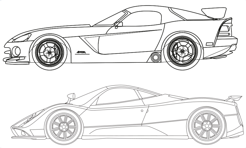
Figure 19-2: The Dodge Viper (top) and Pagani Zonda (bottom) are two sports cars with different engine locations.
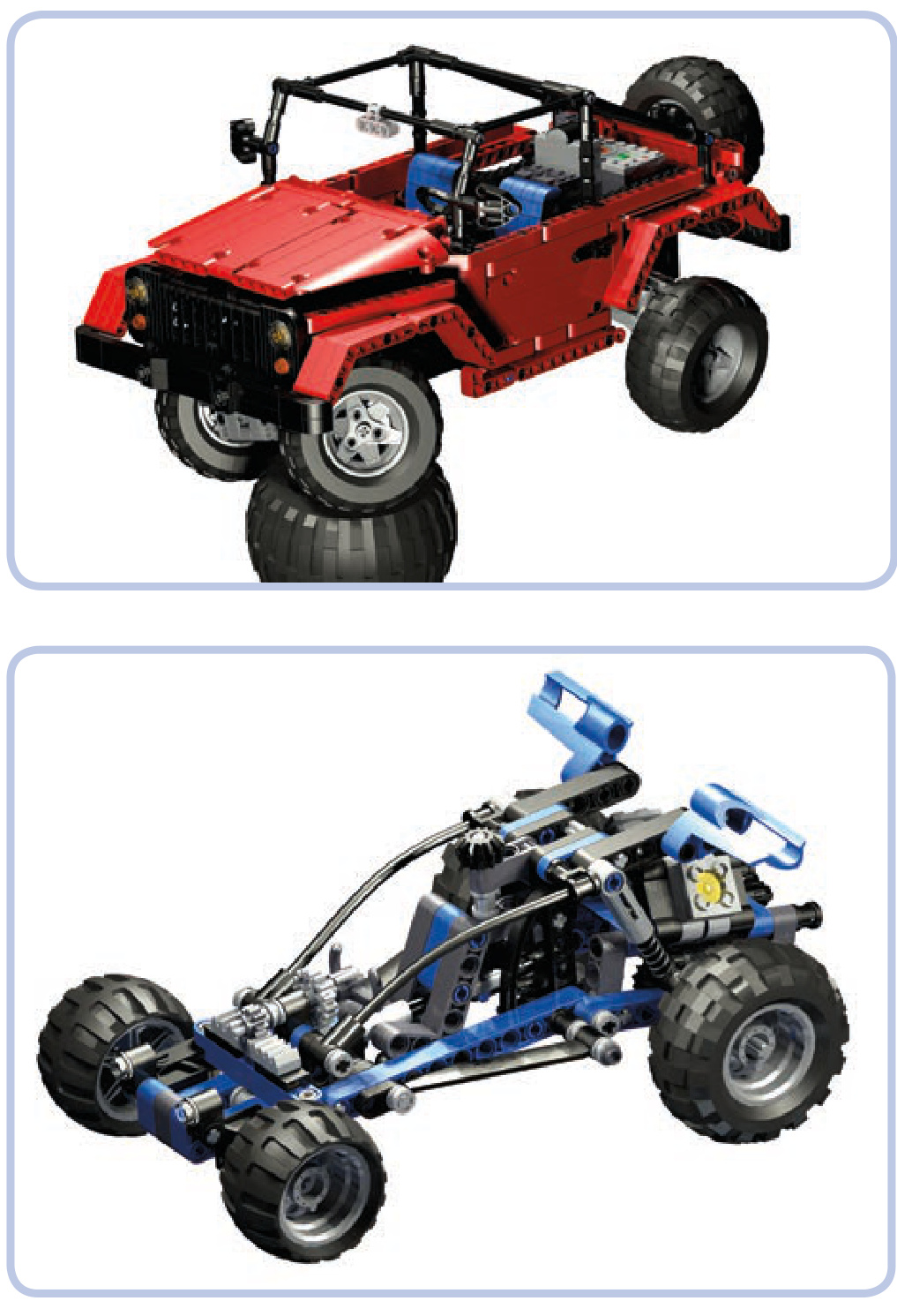
Figure 19-3: My model of the Jeep Wrangler Rubicon, which is a small open-top car, had motors under the hood and the battery and IR receiver in the trunk. This way it had a good weight distribution and plenty of space left for some decorative elements in the cabin interior, including seats and the steering wheel.
Figure 19-4: LEGO 8296 set features a simple dune buggy with a typical pipebuilt body.
Longnose trucks definitely have more advantages for model builders: They offer more internal space, especially with the addition of a sleeper module, and there are more ways to experiment with their aesthetics. Note that in the trucks with no hood—longnose and cab-over-engine alike— the engine is accessed by lifting up the cabin, which tilts
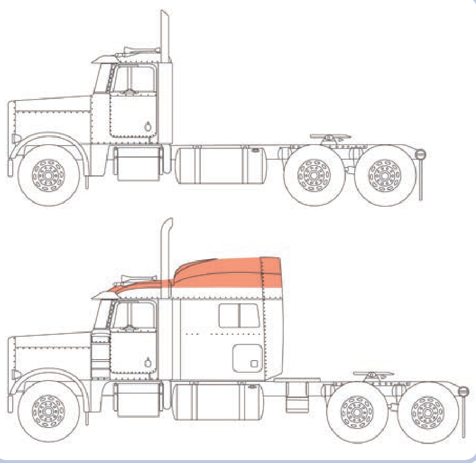
Figure 19-5: The longnose Peterbilt truck, shown without the sleeper module (top) and with sleeper module (bottom). The air deflector is marked with orange.
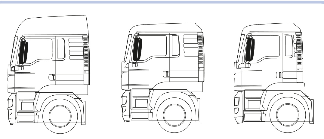
Figure 19-6: Three cabin variants of the same European MAN TGS truck (from left to right): with tall airfoil and resting space, with low airfoil and resting space, with low airfoil and no resting space
forward. This is difficult to include in a model, and engines are often omitted completely from the models of cab-overengine trucks, especially since engines use space that is best suited for the steering system. Trucks with hoods, on the other hand, can have working hoods with replicas of the engine beneath, and this still leaves plenty of space below the cabin for steering mechanisms. As Figure 19-7 shows, the space under the hood can be used to create a fairly complex engine replica, as well as to house some electric components.
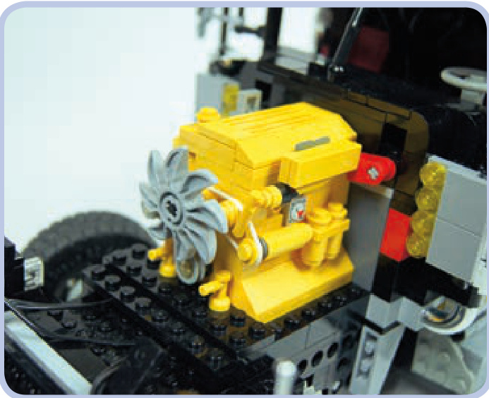
Figure 19-7: The hood of my tow truck model housed a replica of the original Caterpillar engine and a Power Functions battery, located between the engine and the front of the cabin. The red connector piece adjacent to the engine functioned as the model’s master power switch.
motorcycles
Motorcycles, like the one shown in Figure 19-8, are very challenging to model for a number of reasons—the most important one being the fact that they have only two wheels. In order to stand on its own, a model requires at least three wheels (or wide, flat tires). To enable a motorcycle model to stand on its own, we can add a small, unobtrusive wheel or a full sidecar. Sidecars have the advantage of offering plenty of internal space near the bike’s rear wheel, so they can be used to house a propulsion motor. Another alternative is to build a trike or a quad, which is something like a fourwheeled bike.
Other difficulties you may encounter while building bikes include motorizing the steering system, the limited variety and size of matching LEGO wheels, and the overall small size and exposed body, which make it difficult to install any large electric components. All in all, motorcycles are aesthetically interesting models to build but difficult ones to motorize. Among the LEGO sets, as well as among MOCs, most motorcycles have only basic functions, such as a suspension system and drivetrain with a replica of an engine, while motorized models are a rarity. For an example of a motorized model, see Figure 19-9.
Figure 19-8: The LEGO 8422 set features a typical motorcycle with a suspension system and a piston engine connected to the real wheel. Note that even though the model uses one of the largest LEGO wheels in existence, it’s still rather small.
tracked vehicles
Tracked vehicles are a diverse group, but they are almost always fairly easy to model. First of all, the use of the tracks eliminates the need for any complex steering system (unless we decide to use a subtractor). Secondly, the suspension system is located either on the sides or on the bottom of the hull, taking little or no space inside the model, as shown in Figure 19-10. In fact, the hull of most tracked vehicles is a simple box with tracks on its sides and plenty of space inside, and it also functions as a body frame.
Tanks have large hulls whose space can be arranged in several ways. After building plenty of tank models, I have developed a reliable arrangement: The propulsion motors go in the lower-rear part of the hull, with IR receivers on top of them. For modern tanks with large turrets, the receivers have to be moved to the very rear end of the hull to avoid being blotted out. The central part of the hull can house the power supply with the turret rotation mechanism on top of it. The front part can be used for the power supply as well, but not for the IR receivers, as the models are typically controlled from behind. The turret itself can house the gun control
Figure 19-9: The Dodge Tomahawk concept motorcycle comes with double front and rear wheels, thus providing four fulcrums rather than two. I built a motorized model of this bike to prove that it could be motorized and drive stably; however, it couldn’t turn because it was too small to house a steering system and a propulsion system at the same time.
Figure 19-10: The Swedish Hagglunds BV 206 personnel carrier consisted of two parts connected by an articulated joint. This very tiny model housed one steering and two propulsion motors, a battery and an IR receiver, while its simple suspension was located entirely within the tracks.
mechanism, but it’s also a good, well-exposed place for the IR receivers if it’s tall enough to house them. See examples of tanks I have modeled in Figures 19-11 and 19-12.
You might also want to model half-track vehicles, which have regular steered front wheels and tracks replacing the rear wheels, as shown in Figure 19-13. This rare combination is used almost exclusively in military vehicles, such as trucks and armored personnel carriers. Most of the vehicle, including the cabin, the front axle, and the engine bay, needs no alteration from a wheeled version, while the tracks need no steering system, as steering is provided by the front wheels. Some of the heaviest historical half-tracks, however, included a braking system that slowed one of the tracks while turning to improve handling of the vehicle.
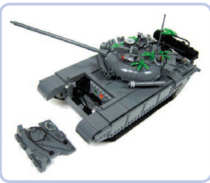
Figure 19-11: My T-72M tank model was small and low, with an angled glacis plate that left very little space in the front of the hull. The very front of the hull housed only some wires, and the glacis plate was removed to access the battery.
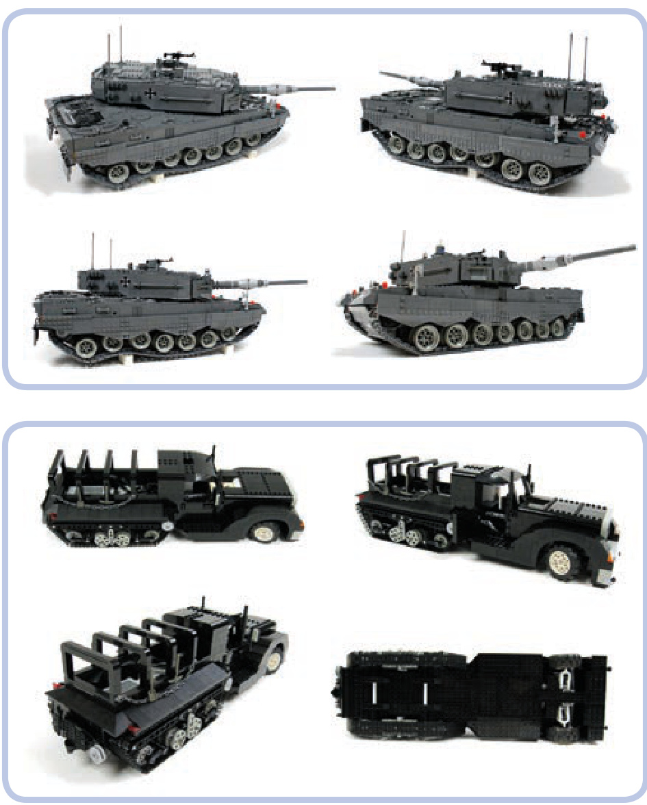
Figure 19-12: My model of the Leopard 2A4 tank was large and heavy. I used four XL motors for propulsion, powered from two battery boxes located in the middle of the hull. It wasn’t fast, but it had plenty of torque and handled obstacles extremely well for its weight.
Figure 19-13: My model of a half-track truck. Vehicles of this type are driven by tracks and steered by front wheels.
aircraft
Modeling aircraft offers plenty of intriguing possibilities and challenges. Such vehicles can be motorized to have rotating propellers or turbines. They can also have working ailerons, elevators, and rudders, as well as retractable gears and flashing position lights. But LEGO aircraft can’t fly.
Not e Building a 100 percent LEGO plane or helicopter capable of flying is physically impossible because of the weight of LEGO pieces and the limited power of LEGO motors. Additionally, an aircraft built exclusively with LEGO pieces would have difficulties with balance and with achieving an aerodynamic profile.
Any aircraft you model can be made even more impressive when installed on a boom that can lift it up and move it around, imitating free flight. The LEGO 8485 set includes such a model, shown in Figure 19-14.
planes
One of the main challenges involved in building a model of a plane is the shape of its hull. A plane hull’s cross section is more or less circular. You can model it with studfull pieces using curved slopes, or you can just mark some edges of the hull with flexible axles. The wings and tail can be modeled with slopes, plates, and tiles, or with axles or even bricks and beams if you mark only the edges, as Figure 19-15 shows.
Minifigure-scale planes can use the ready-made tails, noses, and hull sections that can be found in regular LEGO sets.
Your model can also take advantage of one of the large number of ready-made LEGO propellers, shown in Figure 19-16. These propellers can work in air as well as in water, and when motorized, some of them can generate thrust that is noticeable, though still insufficient for flying.
With jet engines, it’s relatively easy to create mock-ups of turbines that can rotate. Figure 19-17 shows a simple example of a mock-up built around a 4-stud-long bar. You can also use LEGO LEDs with translucent red or translucent orange pieces to illuminate the engine’s nozzle. Installing a small LEGO propeller inside a duct with a round cross section can generate more thrust than when the same propeller works outside the duct.
helicopters
Helicopters are generally easier to model than planes. They have dense hulls, tiny wings or no wings at all, and a single boom with a tail rotor. They offer plenty of internal space and often include more functions than planes do: Some helicopters come with winches to lift loads off the ground, some come with retractable gear, and even the simplest helicopters have large rotating blades that look impressive when motorized.
When it comes to modeling a helicopter, the primary challenges are the windscreen, which has a complex shape in some machines, and the rotors. A typical helicopter comes with a single main rotor with two to six blades and a single tail rotor with two to four blades. Figure 19-18 provides an example of a helicopter with a six-bladed main rotor, which helps the aircraft handle its weight. Some helicopters, such as the Kamov Ka-50 Hokum, come with two main rotors and no tail rotor. The two rotors rotate in opposite directions, and if they are coaxial—which is not always the case, as Figure 19-19 shows—modeling them can be an interesting technical challenge.
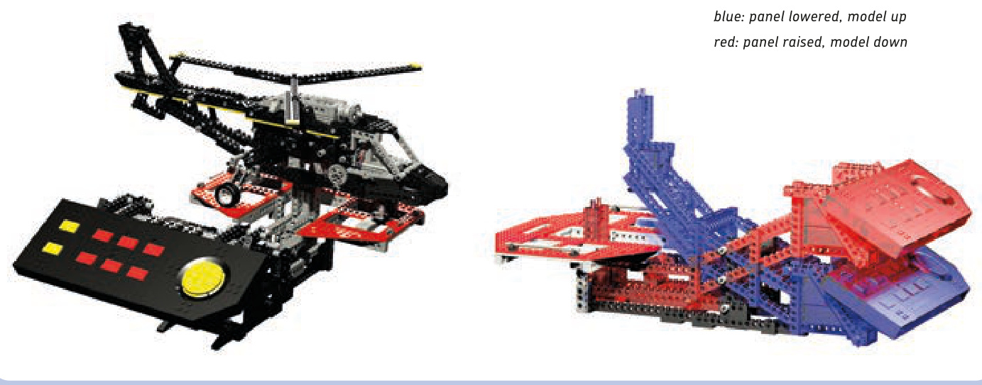
Figure 19-14: The LEGO 8485 Control Center II set features a large helicopter on a simple boom (left). By manually lowering the control panel (right), which acts as the helicopter’s counterbalance on the boom, we can lift the model up and simulate the movement of free flight—for example, the tilting of the hull.
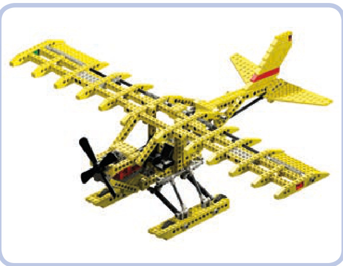
Figure 19-15: The LEGO 8855 Prop Plane set is a fairly typical example of a Technic plane. It has no motors and just basic functions, with parts such as ailerons and elevators controlled by a single yoke.
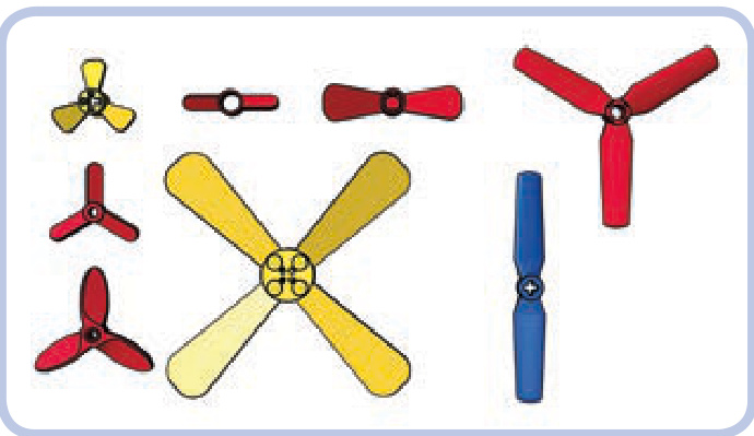
Figure 19-16: The LEGO ready-made propellers with pin holes (red) and axle holes (yellow), along with the #2952 propeller (blue), which can be used in pairs to create a 1-stud-thick, four-bladed propeller.
The tail rotor is usually located on one side of the tail fin. In some helicopters, however, it is mounted inside an opening in the fin. Such a design, shown in Figure 19-20, is called a fantail, and rotors used in it are smaller and have between 8 and 18 blades. It’s very difficult to properly model a fantail because there is no easy way to mount and drive a LEGO rotor inside it.
Figure 19-17: One of many ways to build a small mock-up of a turbine engine with just a few LEGO pieces. The axle joiner (blue) allows us to connect the central bar to a regular axle and thus motorize the “turbine.”
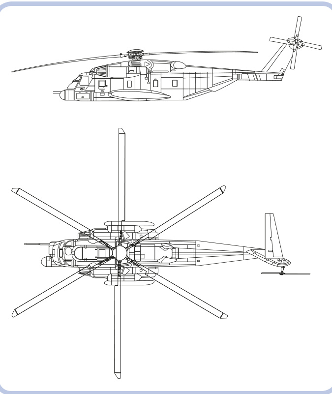
Figure 19-18: The Sikorsky MH-53 Pave Low is a massive military transport helicopter. Its six-bladed main rotor helps to handle its weight, which can reach 21 tons when the chopper fully loaded.
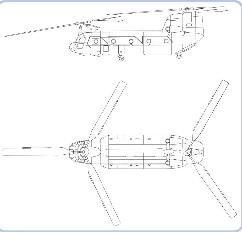
Figure 19-19: The Boeing CH-47 Chinook also comes with two main rotors, located at opposite ends of the hull and at different heights. Such an arrangement is called a tandem.
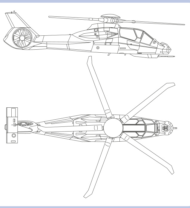
Figure 19-20: The Boeing Sikorsky RAH-66 Comanche was designed to be an advanced reconnaissance and attack helicopter. It used a fantail instead of a typical rear rotor, and the complex shape of its hull resulted from incorporating stealth technologies.
The real main rotor head of any helicopter is an advanced mechanism, allowing adjustments to the pitch of its individual blades or all blades together to weather conditions. This enables the vehicle to perform complex movements, such as flying backward or sideways. A simple mechanical solution allowing the rotor to tilt forward and backward or left and right is shown in Figure 19-21. Tilting the rotor in multiple planes is also possible with the use of towballs and links, as shown in Figure 19-22.
The rotor itself consists of a rotor hub with blades attached around it. The blades can easily be built with plates and tiles or with ready-made pieces from the 9396 Helicopter set, though building the rotor hub to connect these blades can be more difficult. Figures 19-23 to 19-25 show example hubs, with short red plates noting blade placement.
Now that you’ve seen the possibilities and challenges of different vehicle types, it’s up to you to choose what to model. Assuming that you have a model in mind ready to scale, proceed to the next chapter, which explains how to model it accurately.
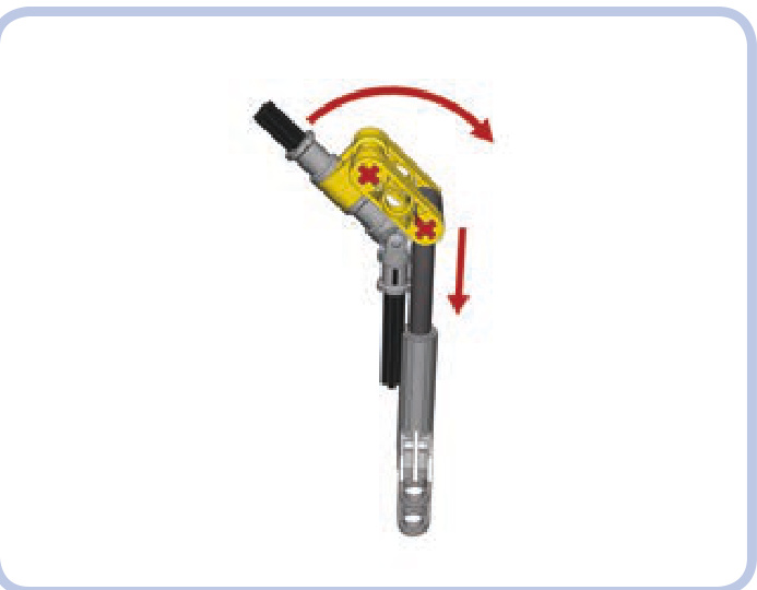
Figure 19-21: An example of a simple rotor-tilting mechanism. The black axles with a universal joint are the driveshaft, connecting the rotor on the top with a motor on the bottom. Retracting and extending the linear actuator changes the angle of the axle above the joint and thus of the whole rotor.
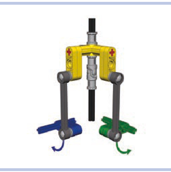
Figure 19-22: A mechanism for tilting a rotor in two planes. Rotating the green axle tilts the rotor in one plane—for example, forward and backward— while rotating the blue axle tilts the rotor in another plane—for example, left and right. Thanks to the use of links and towballs, both angles of the rotor can be changed simultaneously without interference.
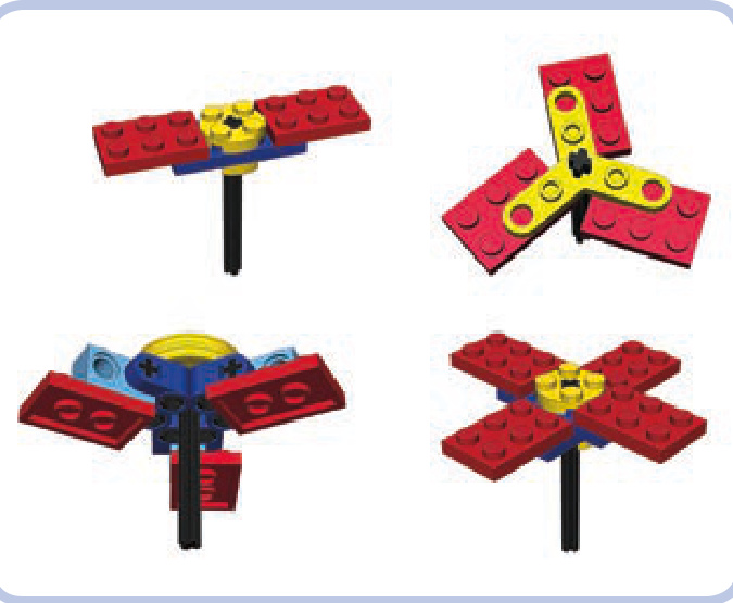
Figure 19-23: Simple hubs with two to four blades
Figure 19-24: A six-bladed hub can be built by doubling the three-bladed version or by simply attaching the blades to a wedge belt wheel with pins so that the centrifugal force of the rotating rotor aligns them.
Figure 19-25: Finally, a hub with any number of blades can be built by attaching plates with clips to the edge of a wedge belt wheel. This solution, invented by Polish builder Marcin “Mrutek” Rutkowski, results in a surprisingly robust setup, which can be made even stronger if you attach blades using two wedge belt wheels and two clips. You will, however, need to align the blades by hand, so a protractor may be useful.

20
Scaling is a fairly straightforward process requiring simple multiplication and division. To begin, we need two things: a blueprint of the original object and a point of reference that will determine the resulting size of our model.
blueprints
A blueprint is a technical drawing that typically includes a front, side, rear, and top view, as Figure 20-1 shows. We’ll want to find blueprints whose views show the object at the same scale.
scaling a model
A proper blueprint shows only the important edges of the object, without any filling, shading, colors, or textures. Figure 20-2 shows the same object with and without the central perspective—that is, a “vanishing point.” As you can see, perspective can distort the image and thus affect the measurements we take from it.
Where do you find blueprints? The best free source is http://www.the-blueprints.com/. If you can’t find the blueprint you need there, you can check LEGO MOCs websites, like http://www.brickshelf.com/ and http://mocpages.com/, as some builders publish their MOCs along with the blueprints they used. If you plan to model construction equipment, such as excavators, dump trucks, and so on, you can check the website of the original machine’s manufacturer. Many major manufacturers, such as Caterpillar, JCB, Komatsu, Liebherr, and Volvo, publish product brochures, usually as PDF files, that include a blueprint showing a machine’s dimensions in at least two views. Alternatively, you can look for 3-D models—some vehicles are popular with 3-D artists, who often present their work on the Internet in a blueprint-like form. Model-building kits can also be a source of high-quality blueprints, as their instructions often include painting diagrams that look exactly like blueprints. For example, Revell offers many instructions for free (http://www.revell.com/support/instructions.html).
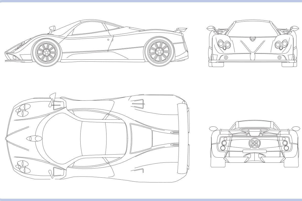
Figure 20-1: A typical blueprint showing the Pagani Zonda sports car
Figure 20-2: Side view of the same model with central perspective (top) and without central perspective (bottom)
As a last resort, you can use photographs in place of a blueprint. The ideal set of photos shows the entire unobstructed vehicle from direct angles, preferably from a distance. The photos should obviously be as large, clean, and bright as possible, and they should be scaled to show the object at the same size from various angles. Figures 20-3 and 20-4 provide examples of unusable and usable photos, respectively.
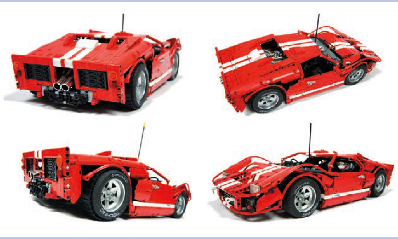
Figure 20-3: These photos can’t be used in place of a blueprint. They show the object from mixed angles (for example, rear/side), and they are highly distorted by perspective, as a result of having been taken from a short distance.
Figure 20-4: These photos are perfectly usable in place of a blueprint. They present the object from direct angles, and they are taken from far enough away that the images are not distorted.
points of reference
A point of reference is a constituent part that determines the size of a model. We use it to calculate how much smaller (or larger) than the original object the model has to be. Basically, we need some part in our model whose size can be compared with the size of its real counterpart. For wheeled vehicles, comparing wheels—or, more specifically, the diam eter of tires—works best. Because LEGO wheels have a fixed size, we can easily scale the rest of our model to be the appropriate size.
The general rule of thumb for any build is to select the vehicle’s most specialized part. Since we can’t adjust the size of LEGO wheels, tracks, or propellers, we have to start with them as a reference point and then scale accordingly. Bear in mind other space constraints, like a vehicle’s hull dimensions and your model’s target functionality, as you work from your point of reference.
For tracked vehicles, we can use the width of the tracks as a reference point. This is an optimal reference point because a poor fit is usually more noticeable when it comes to track width than, for instance, the diameter of the sprocket wheels.
A helicopter model can be scaled using the ready-made LEGO propeller that will be used as the tail rotor. A jet plane model can be scaled using the cylindrical LEGO piece that will be used as the jet engine housing. And a boat can be scaled using a ready-made LEGO hull (these come in many variants, including watertight ones).
scaling
Let’s assume we have a good blueprint of the vehicle we want to scale and we have chosen a LEGO wheel as our point of reference. Now we can begin the actual scaling. (Note that the following process works the same way regardless of the part we use as our reference point.)
We will be taking various measurements off the blueprint. We can do that directly in the blueprint file, measuring distances with a program such as GIMP or Windows Paint. When you open the file in Paint, for example, and draw a line, the dimensions of the line (in pixels) will be shown in the lower-right corner of the program window. By holding down the shift key while drawing, you can make sure the line is perfectly horizontal or vertical. The other way to measure the blueprint is to print it out and simply use a ruler. Personally, I prefer this method, as it allows me to add notes to the printout, and it doesn’t require using a computer every time I need to measure something. The notes on such a blueprint can become quite elaborate and include a great deal of information, as Figure 20-5 shows.
First, we have to determine the scaling ratio—the difference in dimensions between the blueprint and our model—which will allow us to calculate all of our model’s target dimensions. We can do this by comparing the size of our point of reference—in this case, a LEGO wheel—with its counterpart on the blueprint.
Let’s assume that we want to scale a Dodge Viper using a wheel from the 8448 Super Street Sensation set, which has a diameter of 10 studs. We begin by measuring the diameter of the wheel on a blueprint (indicated by the blue line in Figure 20-6), and the result is . Now we divide the diameter of our LEGO wheel by the diameter of the wheel on the blueprint:
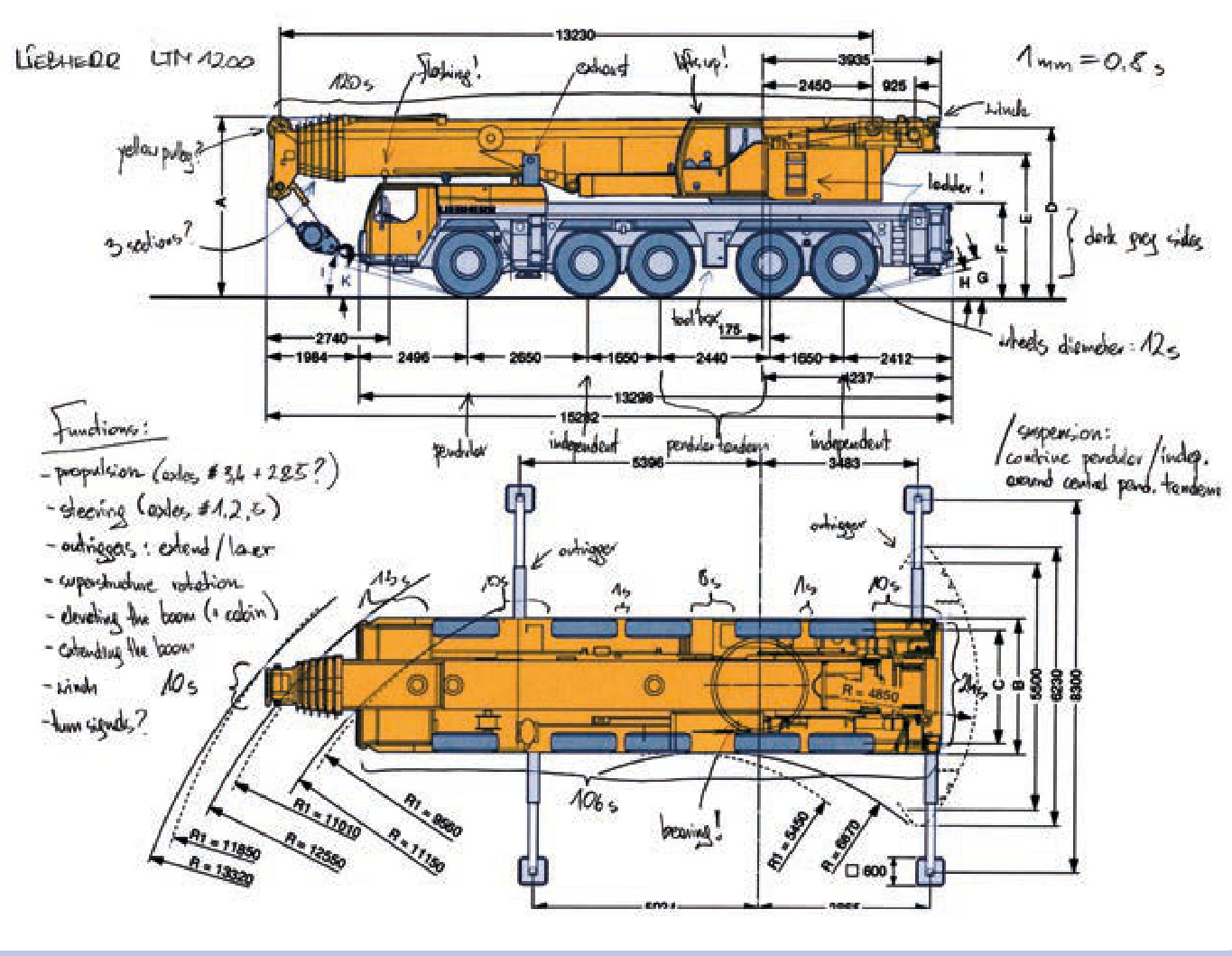
Figure 20-5: A printout of a Liebherr LTM1200 mobile telescopic crane blueprint. All basic dimensions and functions are marked, and the scaling ratio is noted in the upper-right corner. The blueprint comes from the manufacturer’s product brochure.
We can round this value to 0.36 studs/mm. This is our scaling ratio—it shows how many studs are equal to on the blueprint:
Now we can calculate any dimension of our LEGO model by measuring the corresponding dimension on the blueprint and multiplying it by the scaling ratio. For example, we can start with the width of the vehicle, which is on the blueprint.
81 mm´ .36 studs studs
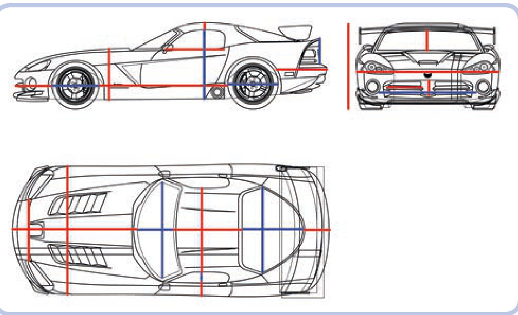
Figure 20-6: A Dodge Viper’s blueprint with three views. Colored lines mark various dimensions that can be easily measured.
The width of my model should be 29 studs.
We can summarize the calculations we have done with the following formulas:
Putting it all together, we get this:
Let’s put the formula to work to see how wide the same model would have to be if I scaled it for smaller LEGO wheels:
Dimensio studs
And if I scaled for slightly bigger LEGO wheels:
Dimension studs
With the scaling ratio determined, we can proceed to take all the measurements we need from the blueprint. As Figure 20-6 shows, practically any object can be broken into a number of lines marking distances along the three basic dimensions: length, width, and depth.
For our Dodge Viper, the most important dimensions to calculate are the following:
N Total length, width, and height
N Height from the bottom of the body to the top of the cabin
N Height from the bottom of the side window to the top of the cabin
Height from the bottom of the body to the top of the hood
Length of the body behind the rear wheels
N Length of the body in front of the front wheels
Distance between the front and rear wheels
N Length, width, and height of the windshield and all windows
N Length of the trunk and hood
Length and width of the cabin roof
Distance between the headlights
Distance between the side window and the edge of the body
N Length and width of the front grille
N Height of the body’s rear end above the bumper
Once you have your dimensions, it is possible to determine the scale of your model. To do this, we need to compare certain dimensions of the model with the dimensions of the original object using the same units. It’s a good idea to check body width—it’s one of the most important dimensions of any vehicle. Let’s assume that I have built my Dodge Viper model 29 studs wide, as originally planned. Because 1 stud equals , 29 studs equal . According to Dodge, the body width of the real car is . Now, 1,920 / 232 equals 8.276. We can round this number to 8, which makes 1:8 the scale of my Viper. In other words, my model is 8 times smaller than the real vehicle.
NOT E Before dividing, make sure you’re using the same units for both dimensions.
Figures 20-7 to 20-9 show the most important dimensions of other types of vehicles.
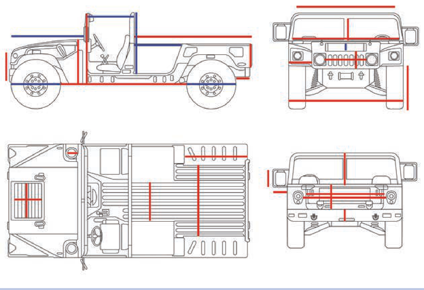
Figure 20-7: A blueprint of the Humvee with the core dimensions marked. The angular silhouette of this car is convenient for both measuring and modeling.
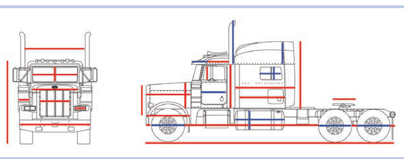
Figure 20-8: A blueprint of the Peterbilt 379 truck with the core dimensions marked. These include the dimensions of the airfoil, fifth wheel, hood, and side fuel tanks.
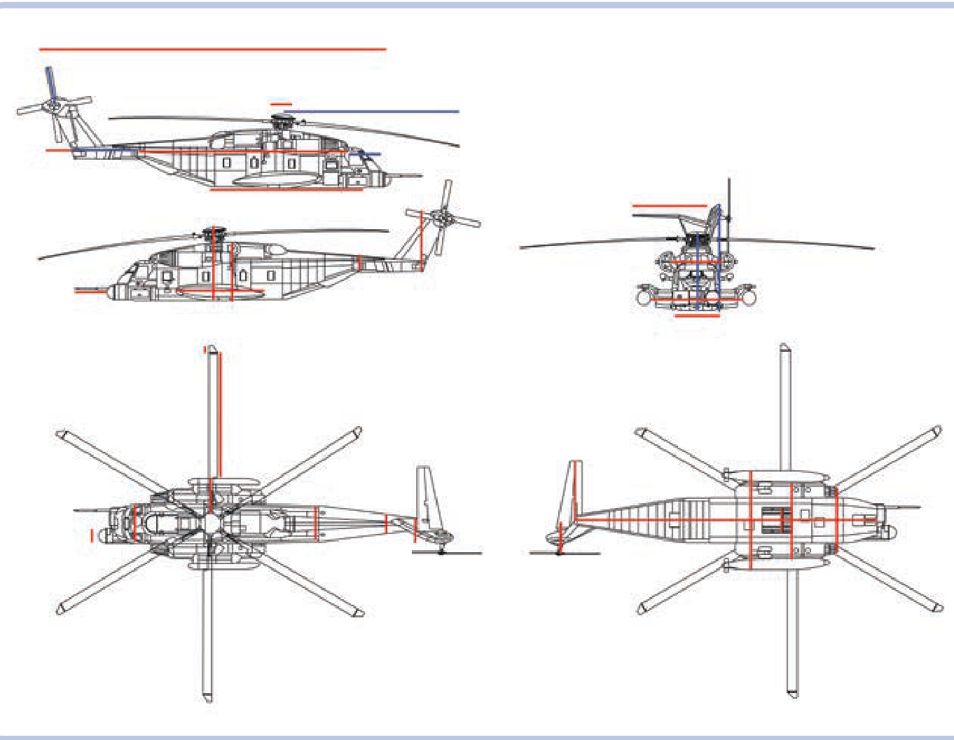
Figure 20-9: A blueprint of the Sikorsky MH-53 Pave Low helicopter with the core dimensions marked. These include the dimensions of the hull, tail boom, tail fin, both rotors, and main rotor hub.
Here is the formula:
where
Dimension the dimension on the model Dimensio the same dimension on the real object
Sometimes you may want to build a model in an already determined scale. For example, you might want to build a model that matches the size of someone else’s construction. Building a model in an already determined scale makes cal culating the dimensions slightly more complicated. First, you need to know at least one dimension of the original object and compare it to the same dimension on the blueprint. Let’s assume I want to build the wide Dodge Viper in a 1:12 scale. The width on the blueprint is . We need to calculate the blueprint ratio, that is, the difference between the dimensions of the real car and those of the car on the blueprint. In this case, the ratio is , which equals 23.7. We can round the result to 24 to get our blueprint ratio. The formula is as follows:
Now we can proceed to calculate any dimension by measuring the part on the blueprint, multiplying it by the blueprint ratio, and then dividing it by the scale. For example, let’s check to see what size wheels I’m going to need for my 1:12 model. The wheel’s diameter on the blueprint is . Therefore, we perform the following calculation:
This means the diameter of the model’s wheels should be , which equals exactly 7 studs.
Given this information, we can calculate any dimension for a predetermined scale using the following formula:
1 stud Dimension Dimensionblueprint ×Blueprint Ratio×Scale× 8 mm
Of course, the actual vehicle consists of more complex shapes than just those created by perpendicular lines, and these shapes need to be approximated with LEGO pieces. But by keeping our approximation within the core dimensions, we make sure the model has the right size, right angles, and right proportions. A model that has few details awry but accurate proportions always looks better than a model with plenty of intricate details but wrong proportions. Details can impress, of course, but they can’t hide errors in the proportions of the model.
Now that we can calculate the important dimensions, the next chapter will focus on modeling and other details.
21
the modeling process
Now that you have your ideal model in mind and you’ve learned how to scale all dimensions of the object accurately, it’s time to start building. This is where you start putting your plans to the test, figuring out all those little forgotten details.
size matters
While many builders are tempted to build big, and while size can indeed be an impressive feature of any LEGO construction, Technic models don’t necessarily benefit from large size. Going big creates a number of problems that increase rapidly with size, including significant stress on many sensitive pieces and problems with the mobility, balance, and structural integrity of a model. One of my models was tall and very heavy, with a tracked chassis that I thought was
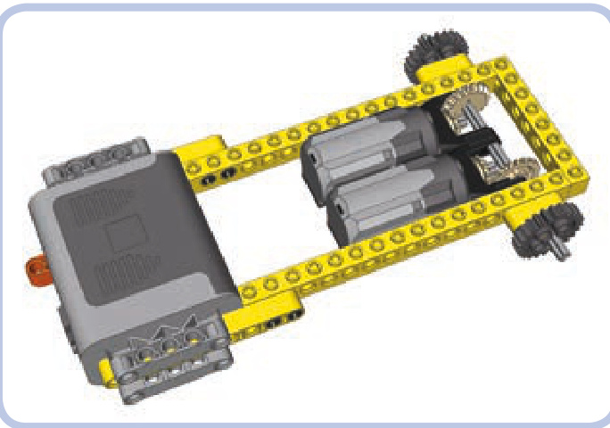
Figure 21-1: An 8-stud-wide hull with a 6-stud-wide internal space, large enough to house two Medium motors side by side, one driving the left sprocket wheel and the other driving the right sprocket wheel. A Power Functions battery box can also be housed inside if you make holes for it in the sides of the hull. The protruding parts of the battery box can be concealed inside the tracks.
strongly reinforced. When it reached a weight of 7 kg, the chassis was bending so much that it couldn’t keep the body stable while moving. Even sturdy Technic bricks become quite elastic if the load exerted on them is large enough.
A good rule of thumb, especially for less experienced builders, is to build as big as needed rather than as big as possible. In other words, you should aim to make your model as small as possible. To estimate how small it can be, you have to consider the largest single-piece elements it’s going to house, such as battery boxes, motors, and IR receivers. Tracked vehicles are a good example here—their box-shaped hulls need to be wide enough for two motors set either side by side (see Figure 21-1) or back to back (see Figure 21-2). If a narrower hull is used, wider elements—such as the power supply—must be set above the tracks.
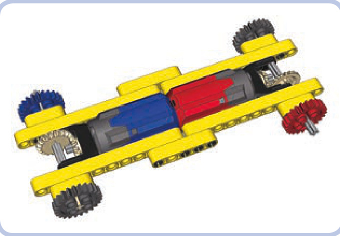
Figure 21-2: A 5-stud-wide hull with a 3-stud-wide internal space, large enough to house two PF Medium motors back to back. As the red and blue colors indicate, one motor drives the front right sprocket wheel, while the other drives the rear left one. The remaining two sprockets are idlers. Wider elements, such as the power supply, must be moved above the tracks where the hull is wider.
There are many creative ways in which you can fit large elements into a small model. For example, when building an excavator, you can try to fit small motors, such as PF Mediums, in the arm if it’s massive enough, or you can install them between the tracks if the ground clearance allows (see Figure 21-3). You can also try to disguise the motors. One of the trucks I built could house motors only in its cargo hold. When I covered the motors up with plates, it looked like the cargo hold was gone. When I left the motors exposed, they looked like a load carried by the truck. Try to experiment— the more solutions you attempt, the closer you are to finding the best one.
Figure 21-3: My model of the Liebherr R944C tunneling excavator housed more motors in the chassis than it did in the superstructure, at the cost of nearly zero ground clearance. With more space available inside the superstructure, I was able to take better care of its aesthetics.
The complexity of a model is another issue. Very complex models are always impressive, but they are also very difficult to build. My most complex model so far, the tow truck shown in Figure 21-4, housed 17 motors and nearly of electrical wires. To make it possible, I had to provide special isolated ducts inside its body specifically for wires. It’s always a good idea to keep in mind that complexity should be a result, not a goal in itself.
Regardless of how confident you feel, it’s good to gather some experience building reasonably small and simple models before trying something big and complex. With enough experience, you will notice that big and complex vehicles are often basically a sum of what you’ve done with smaller ones. For example, you might combine one model’s suspension with another’s gearbox. Bigger and more complex projects feel more rewarding when completed, but they are also more likely to fail.
Figure 21-4: My tow truck model housed 17 motors and nearly 19 meters of electrical wires, requiring ducts inside the body. Note that the mechanical and electrical parts are all enclosed within the body, with a few minor exceptions, such as the PF Medium motor, which is partially visible by the boom’s winch, and the gears of the steering system, which are visible next to the front mudguard.
wheels
Most LEGO wheels have different proportions than wheels used in real vehicles—they are significantly wider. While this may not be a big problem for many types of models, it can become an issue for vehicles that have more than two wheels on a single axle, trucks being the primary example.
The vast majority of trucks use double wheels on all rear axles. Models with single wheels, no matter how wide, just don’t look accurate. For example, the wheels, a favorite of LEGO truck builders, are 5 studs wide when doubled. That means that an axle with four wheels of this type needs a 10-stud-wide space just for the wheels alone. As Figure 21-5 shows, such an axle can’t possibly get narrower than 16 studs, unless you abandon the differential.
Figure 21-5: It’s possible to build a driven axle with four wheels that fits within a 16-stud width—but just barely.
As you can see in Figure 21-6, the width of the driven axle is one of the major factors affecting the size of the model. And things get even more difficult when there is a suspension system, especially an independent suspension that takes plenty of space between the chassis and the wheels.
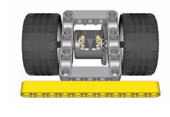
Figure 21-6: Small wheels are often wide, so it’s difficult to use more than two per axle. These wheels, often used in small trucks, are 3 studs wide with just a 5.5-stud diameter. An axle with two of these is 11 studs wide, while an axle with four would be 17 studs wide.
Another important issue is the profile of the tire, which can be rectangular (as with regular tires) or round (as with so-called balloon tires). Figure 21-7 shows the same wheel with a regular and a balloon tire. The balloon tire is bigger, with a slightly larger diameter, but its side surface is smaller because of its profile. Balloon tires look good fully exposed, but when viewed from the side, especially when enclosed within the body, they can actually appear smaller than regular tires, as Figure 21-8 demonstrates.
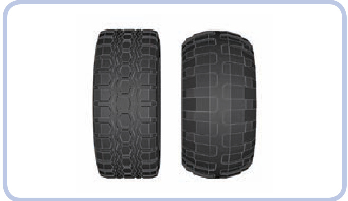
Figure 21-7: The so-called Technic Racing wheel with a regular tire (left) and a balloon tire (right). The tires are very similar in size, but the balloon variant is softer, has deeper tread, and usually works better on rough terrain.
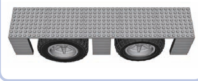
Figure 21-8: The Technic Racing wheel with a regular tire (left) and a balloon tire (right), viewed from the side and under a mudguard. The regular tire appears bigger because of its larger side surface, even though its diameter is actually slightly smaller than that of the balloon tire.
The final issue involving wheels is steering geometry. In most real cars, when the wheels are steered, they rotate around a pivot point—that is, a vertical axle that goes nearly through their center. As the wheel is turned left or right, its center stays in place, as shown in Figure 21-9. The only LEGO wheels that follow this behavior are from the 8448 Super Street Sensation set, shown in Figure 21-10. The other wheels rotate around a pivot point that is near their side but far from their center. This means that their centers actually move around when they are turned, as shown in Figure 21-11. LEGO portal axles are most problematic when it comes to steering geometry due to the distance between the wheel and the pivot point (see Figure 21-12).
The crucial difference between the two behaviors is the amount of free space required around the wheel in order for it to turn. Wheels with “real” steering geometry require very little space, and they fit within very tight mudguards. Wheels with the LEGO steering geometry require much more space, as they move back and forth relative to the body when being turned. This means that steered wheels in LEGO models need bigger mudguards than real steered wheels.
The difference in the size of the mudguards can also affect the look of the LEGO model. LEGO mudguards are larger than those of the original vehicle, and the wheels appear smaller inside them. Figure 21-13 shows the difference.
As you can see, wheels require careful consideration during the modeling process. It’s a common mistake to make them too small, which is more evident in a finished model than when they are too big. Many inexperienced builders produce otherwise well-designed models on wheels that are clearly too small. When in doubt, try to make your wheels too big rather than too small.
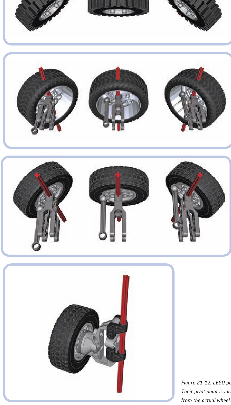
Figure 21-9: The steering geometry of a real vehicle’s wheel: As the wheel is steered, it rotates around a pivot point going through its center, marked in this series of images by an “imaginary” red axle.
Figure 21-10: Of all existing LEGO wheels, only the 8448 set’s wheels rotate around their centers when steered—and they are still a little off.
Figure 21-11: When steered, a typical LEGO wheel rotates around a pivot point that is often well outside it. It requires more free space around the wheel, and it also makes the front of the vehicle move while steering in place.
Figure 21-12: LEGO portal axles are worst in terms of steering geometry. Their pivot point is located between the chassis and the gear hub, quite far
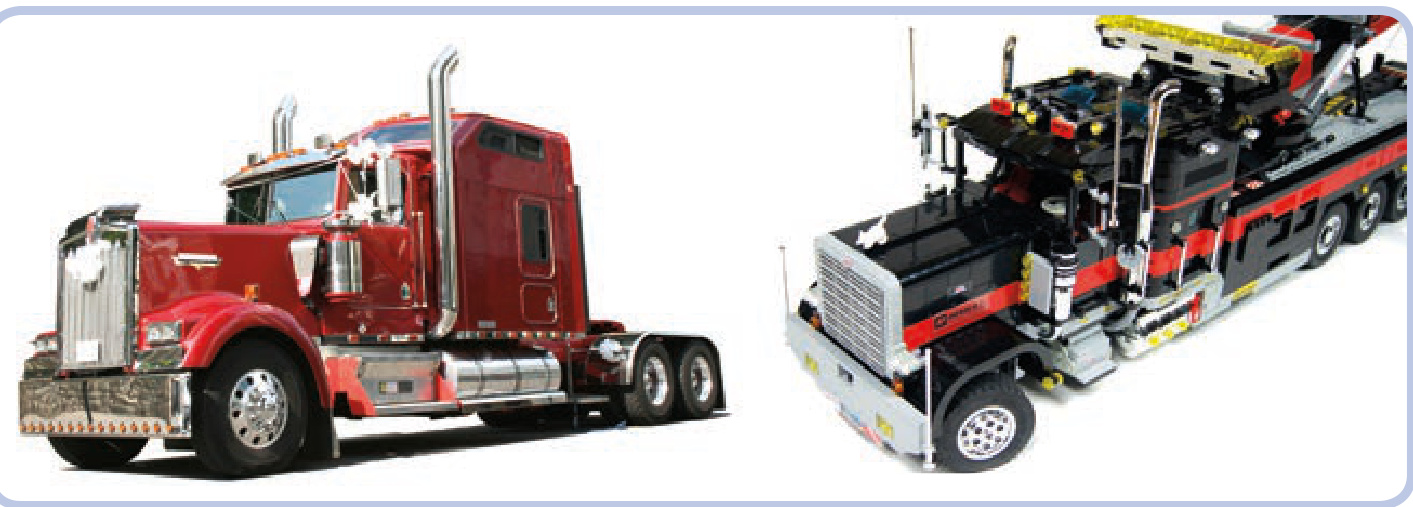
Figure 21-13: Because of their unrealistic steering geometry, LEGO wheels need more spacious mudguards than real wheels do. If the mudguards of my tow truck weren’t sized up relative to the real ones, the wheels would collide with them.
other circular elements
Circular parts are quite tricky to model. You either have to use ready-made pieces, whose variety and availability are limited, or create complex structures of many small pieces, which are fragile and can disintegrate in an instant if sufficient stress is applied. Figures 21-14 and 21-15 show examples of such structures.
colors
Colors are a tricky issue when it comes to LEGO pieces. Typical Technic sets use a fairly limited palette, with yellow and red being dominant. When choosing a color, you are always limited by the availability of LEGO pieces in a particular color, and it only gets worse with bigger, more complex models that require more pieces to be visible from the outside.
Over the years, more than 150 LEGO colors have been developed, including speckle colors, glitter colors, semitransparent colors, chrome colors, and even a glow-inthe-dark color. Some of the colors have been discontinued, while new ones are added every now and then. Some colors are actually very difficult to tell apart, such as the very light bluish-grey color that dominates the Mindstorms NXT sets and regular white. In terms of the number of pieces they’re used for, the top five LEGO colors are white, black, red, yellow, and blue.
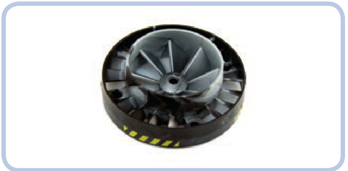
Figure 21-14: The 53983 turbine is an example of a singular circular piece that builders may find disappointing. Not only does it come with a pin hole instead an axle hole, which makes it difficult to drive, but also its inner and outer blades are set in opposite directions, making it useless as a propeller. Finally, the mixed colors appeal to few.
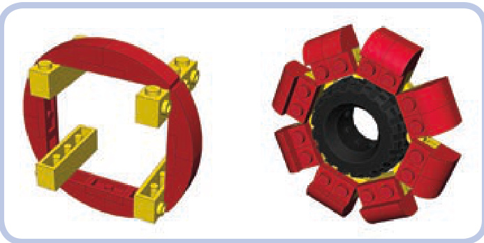
Figure 21-15: Two circular structures built with small basic pieces. One is built around bricks with studs on the side, and the second is built with hinge plates embracing a tire. Both are prone to disintegration if sufficient stress is applied.
When making use of colors in your models, remember that dividing a model into a few unicolored areas almost always produces a better effect than mixing colors. Due to the rectangular shape of most LEGO pieces, mixtures of variously colored pieces just don’t look good and make details difficult to spot.
Building the inside of your model in black conceals gaps in your model’s body. Dark colors also make your model appear larger. Keep in mind that it’s quite common for LEGO builders to substitute certain colors for others when they can’t match the actual vehicle exactly. The most common example is LEGO dark bluish grey, which builders often use in military models instead of khaki and olive, which have no LEGO counterparts.
Sometimes it’s impossible to find a given LEGO piece in the color you desire, but few builders paint their pieces to remedy this issue. This is because painting rarely produces an effect even remotely close to a stock-colored LEGO piece and is often considered cheating in the community. But this isn’t true when it comes to chrome; any LEGO piece looks excellent when chromed, yet there are fewer than 100 types of originally chromed pieces. Consequently, many builders try custom-chroming regular LEGO pieces. The resulting size of the piece is slightly increased by the thin chrome film, so chromed pieces are best used for purely decorative purposes rather than as mechanical elements. During custom-chroming, one part of the piece is usually attached to another piece and remains free of the film; this is the only visible difference between original and custom-chromed LEGO pieces (see Figure 21-16). The two largest sources of custom-chromed LEGO pieces include the ChromeBricks shop, at http://chromebricks.com/, and Chrome Block City, at http://www.bricklink.com/store.asp?p=Aurimax.
Figure 21-16: The wheel in stock metallic silver (left) and custom chromed by Chrome Block City (right). Note that the inside of the custom-chromed piece’s axle hole lacks chrome film and shows that the wheel was originally white.
devil in the details
When building LEGO models, we regularly have to build things smaller than our scale would indicate. It’s very difficult to model details smaller than a single stud, and that means that a lot of approximation is involved. Approximating means that some elements of your model will only vaguely resemble the real ones. You have to make some of them bigger or smaller than they should be and discard some elements entirely. Some builders also resort to custom-made stickers to reproduce the tiniest details.
The barrels of tanks are a particularly good example of approximate building. They almost always consist of a number of sections with slightly different diameters, and it’s difficult to find circular LEGO pieces whose differences in diameter are proportionally the same. Because of this, some parts of the barrel need to be built thinner or thicker, as shown in Figure 21-17. It’s important to consider the impression each of these deviations will create. People expect a tank to look threatening, which it does with a thick barrel. I have built many tanks with barrels too thick, and not a single person noticed it. But when I built one with a barrel too thin, I received plenty of complaints about it.
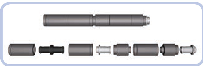
Figure 21-17: Two sections of my T-72M tank’s barrel. They are made of slightly different pieces, but they have identical dimensions and a clearly visible notch between them. The resulting barrel, over 20 studs long, is surprisingly sturdy.
A good way to plan a model is to decide which of its features are most important and to try to retain or even exaggerate those features. If the original object you chose has distinctive big wheels, high ground clearance, or an elongated silhouette, exaggerating those features (within reason) can ensure that your model will be easily recognized. Bear in mind that it’s easy to go over the top, as Figure 21-18 shows.
When looking for distinctive features, always try to think in three dimensions. For example, I have built two models of the Scania trucks, whose distinctive feature is a massive front grille with large horizontal openings. The first model simply used black plates to mimic the openings, and it looked very flat when compared to the real truck. So in the second model, shown in Figures 21-19 and 21-20, I created 1-studdeep openings closed with black plates, and this turned out much better.
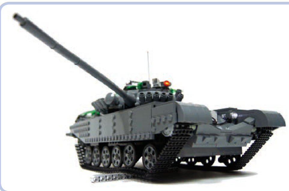
Figure 21-18: Exceptionally high ground clearance is one of the distinctive features of the real T-72M tank. This feature, however, has been exaggerated in my model.
Figure 21-19: The cabin of my second model of the Scania truck with 1-studdeep openings in its distinctive massive grille.
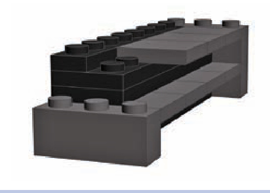
Figure 21-20: I created the openings in my Scania truck’s grille using a mixture of plates and tiles. It was crucial to make the ledges between the openings as thin as possible; they are only 1 tile thick here.
building at odd angles
Both Technic and non-Technic connector pieces can be used to re-create complex angles. Certain vehicles, such as the armored personnel carrier shown in Figure 21-21, have bodies with almost no right angles. By building such models with plates and tiles joined by hinged connectors, shown in Figure 21-22, you can make them look good and weigh little. Some particularly challenging angles can be retained by using Technic connectors with ball joints; Figure 21-23 shows an example of this. Bionicle sets are a good source for these kinds of connectors.
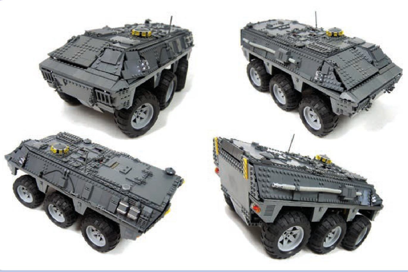
Figure 21-21: The Spanish BMR-2 is a typical armored personnel carrier, with a body made of surfaces connected at complex angles. My model had a body made of plates and tiles kept in place by a system of hinge plates.
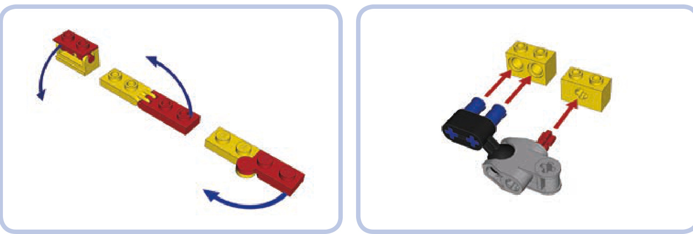
Figure 21-22: Various non-Technic connector pieces, in this case hinge bricks and plates, can keep other pieces oriented at unusual angles.
Figure 21-23: To re-create very complex angles, you may resort to joining certain Technic connectors by a ball joint. The connectors shown here can be combined with regular bricks and keep them at almost any angle.
building cleverly
When working on details, the crucial rule is to match the pieces to the details, not the details to the pieces. In other words, you should focus on how a detail looks and how to reproduce that look with LEGO pieces. Some builders make the mistake of focusing on some piece they want to use and then looking for a detail that looks vaguely similar.
Many objects have little details that are so distinctive that it’s best to include them. For example, when building a Land Rover S2 model, I tried to re-create its distinctive tilted fuel cap. As Figure 21-24 shows, I eventually succeeded using a variant of the brick held at an angle between two regular Technic bricks.
Figure 21-24: An exploded view and a complete assembly of my Land Rover S2 model’s tilted fuel cap. The key was using a variant of a brick and setting it at an angle.
A number of tiny pieces, especially LEGO minifigures’ utensils, can be combined to great effect. For example, many tanks come with a commander’s gun on top of the turret. In large-scale models, these guns have plenty of details, and their look is often unique for a given type of tank. When building a model of the Leopard 2A4 tank, I had the choice to use some simple piece that looked like a gun to me or to use one of the few ready-made LEGO guns. Neither of these options produced an accurate-looking result, so I eventually combined a few minfigures’ utensils, creating the gun shown in Figure 21-25. The gun was built around the body of a
minifigure chainsaw, with a hatchet attached in back and a telescope and a fire hose’s nozzle in front. The gun’s distinctive, large box magazine was made from a few plates with a tile on top, and it was attached to the gun with a plate with a clip. The gun was a total of nine simple pieces, and the result prompted some viewers to ask for instructions to build it or for the address to buy the gun.
Figure 21-25: The commander’s gun from my Leopard 2A4 tank model was built with nine pieces total, including minifigures’ utensils, a few plates, and a tile.
the next step: controlling your models
Finally, remember that the fun doesn’t have to end with building your model. Building a controller for complex models can be a challenge of its own, as exemplified by a model of the Demag H135 excavator built by Emil “Emilus” Oklin´ski (see Figure 21-26). The model uses two NXT bricks in conjunction with another two bricks in the remote to enable realistic remote control. The remote includes complex joysticks built around NXT motors with internal rotation counters, and it takes advantage of the Bluetooth link to connect with the model. Some functions of the model, such as its internal pneumatic compressor, are controlled automatically, and some of its working parameters can be read from the remote. An extensive description of Emil’s model is available at http://www.eurobricks.com/forum/index.php?showtopic= 64131.
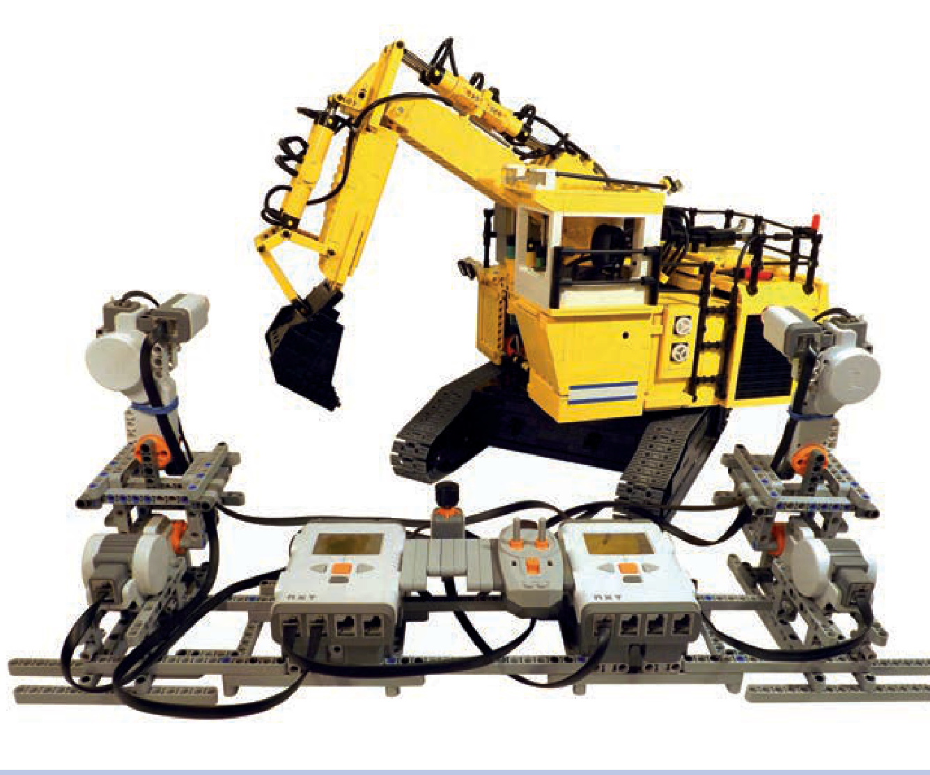
Figure 21-26: The Demag H135 model built by Emil “Emilus” Oklin´ski employed four Mindstorms NXT bricks—two in the remote and another two in the model—to achieve realistic remote control. The complex joysticks based on NXT motors and the use of a Bluetooth link between the remote and the model provided the “driver” with an unparalleled experience.
afterword
I hope that by now you’ve gained a good understanding of the LEGO Technic system and how to build your own models If you’re looking for more avenues to explore, I can recommend other interesting pieces no longer in production, such as elements of the radio control system (8366 set) and the barcode IR system (8479 set), an entire discontinued building system (8369 set), and some very rare modern pieces, like the Power Functions solar panel and energy display (9688 set).
And of course the LEGO Group also keeps introducing new parts, making new solutions possible or simplifying existing designs. Even if you’re a fan of the old school “all studfull” style of building, it pays to keep track of these novelties. For more inspiration, there is the worldwide community of LEGO builders who keep inventing and perfecting designs and sharing their ideas freely for others to try.
Having built well over 120 MOCs in the last few years, I can say that the trial and error of building your own constructions is not the bad part of building—it’s actually the most enjoyable part. Getting to play with your finished working construction is a nice touch, but the real pleasure comes from successfully tackling problems, big and small, which always crop up when you choose to create rather than to build from instructions. With enough trial and error, the only real limit to what you can build is your own imagination. It is my wish that this book helps you to experience plenty of that pleasure as you play with LEGO pieces.
The Unofficial LEGO Advanced Building Techniques Guide
The master builders tips and tricks book
Introduction
What makes a building technique to be advanced? There is no easy answer, advanced is just the way we, adults, feel some building techniques because they do not appeared, at least do not appeared widely, in the officials LEGO building instructions. Most of these techniques are discovered and then used and developed by adults fan of LEGO (AFOLs) or by LEGO designer in the LEGOLAND™ parks. These techniques generally results in a wide array of interesting design and offer a details resolution which was unavailable previously using classical building. Jake McKee precise, in his book “Getting started with LEGO Trains”, that advanced building techniques “enables not only the creation of specialized shapes and angles, but also various non standard dimensions” and “add a wealth of […]designs.”
This late assertion alone is far enough to justify to make a compilation of all these advanced building techniques. That’s the goal of this document. The author goal is not to appropriate to himself these techniques - you are encouraged to check the credits page at the end of the document - but to make a comprehensive collection of tips and tricks, which are widely available on the internet, but which are also, unfortunately, widely scattered and, due to this spreading, mostly unknown and endlessly and uselessly re-discovered.
2007, Didier Enjary
Vocabulary and geometry about LEGO plates and bricks.
The following illustration presents the brick’s top and bottom and the 1x4 brick’s bottom. The top is covered by studs (referring to some patents, it could be also named knobs). The bottom is filled by tubes or bars depending of the brick size1.
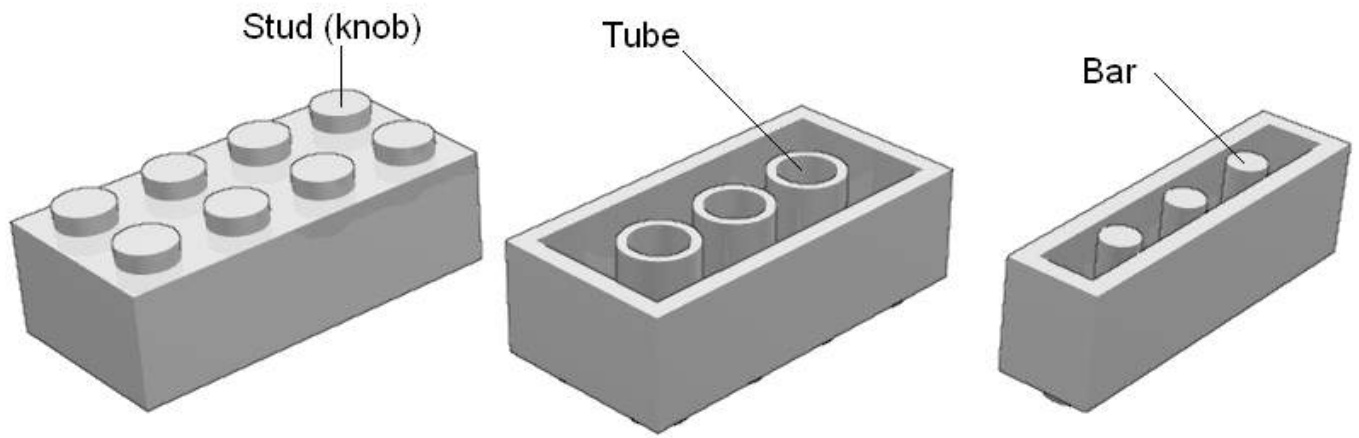
Plates are thin bricks. Technic™ bricks present passing through holes in their side and the studs is scooped out : we talk then about hollow studs.
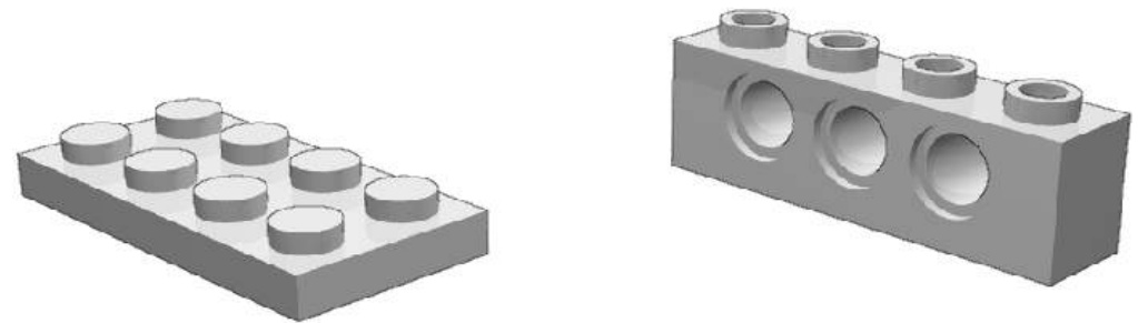
Conventionally, a LEGO Unit (L) equals the 1xn parts width: . The is commonly avoided.
We will also use a subdivision of the LEGO Unit that we call .
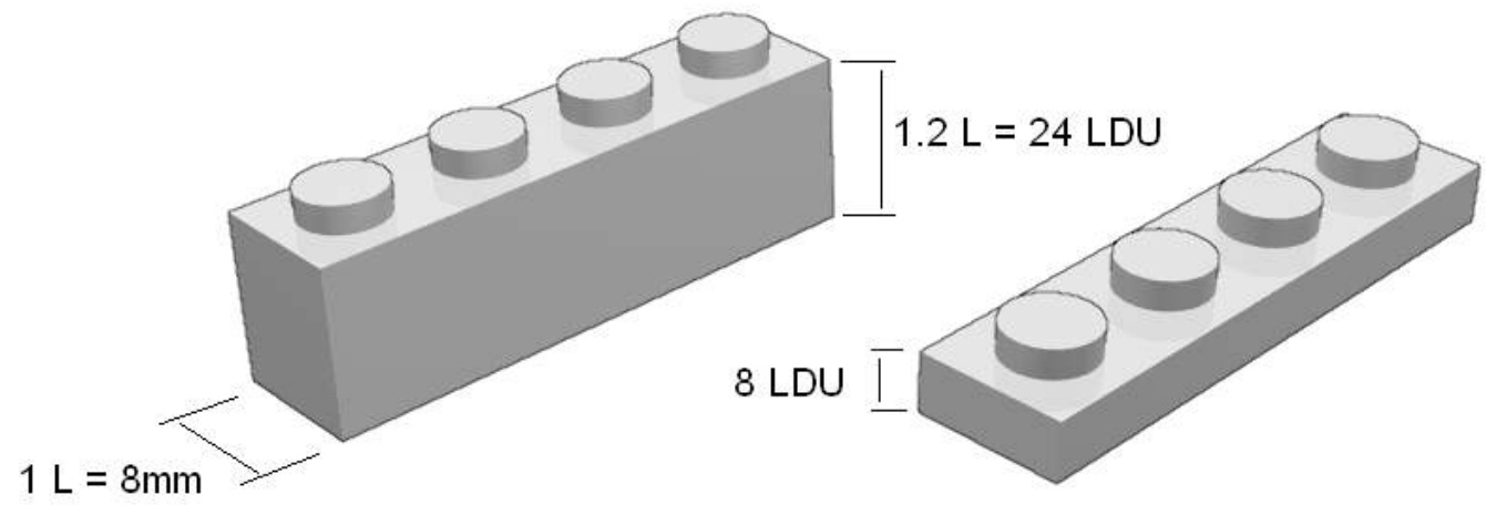
Some people are also used to talk in term of “stud” instead of LEGO Unit. This can lead to confusion as the diameter of a stud is 0.6 “stud”. Others will use “brick” in this same place. Hence, when talking about geometry of parts, LDU should be prefered as it allows to deal with whole numbers and not fractions, and doesn’t lead to confusion with any idiomatic vocabulary.
Measuring a 1xn brick, we see the ratio between height4 (24LDU) and width (20LDU) is 1.2 (6/5). The plate height (8LDU) is a third brick height (24LDU).
The stud diameter and tube (outer) diameter is 12 LDU and is height is a bit higher than 4 LDU. That are also the size of inner diameter of Technic brick axle holes.
Bars’ diameter is 8 LDU. That’s the same of the inner diameter of hollow stud.
General SNOT
SNOT. Isn’t that word funny? In fact not a word but an acronym standing for “Stud Not in the Top”. The LEGO building toy use a building process which consist in stacking parts of various sizes and shapes on top of each other, vertically. SNOT is the name we give to any building tip resulting in the studs of parts not pointing up. SNOT techniques represent a large part of advanced building techniques.
SNOT is made possible thanks to the 5:2 SNOT ratio and to SNOT parts.
The 5:2 SNOT ratio is a direct consequence of the bricks and plates geometry :
5 plates height ( LDU) equal 2 LEGO units width )
One can guess this relationship is not a simple coincidence but a will from the LEGO parts designers. Of course, this ratio fits when multiplying : 10 plates height equals 4L parts length, 15 plates height (5 bricks height) equals 6L parts length and so on. Hence, the 6:5 ratio is a direct consequence of the 5:2 ratio.
The 6:5 ratio
Stud-out SNOT
The 5:2 SNOT ratio is quite useless if you can’t link efficiently the rotated group of parts. SNOT techniques are all about this. Thankfully to specific parts, beginning with SNOT is not so intricate. For instance it exist bricks with studs on their sides:
Brick 1x1 with 2 studs on sides Brick 1x1 with 4 studs on sides Brick 1x4 with studs on side Brick with studs on sides
The basic SNOT scheme is then easily made. These parts with studs on their side are “SNOT parts”.
Bricks with studs on sides are not the only SNOT parts. It exists also a lot of modified parts, among them brackets.
With a bit of curiosity, you will discover that some elementary buildings are efficient when dealing with SNOT. For instance, the Technic 1x1 brick and the half stud pin come rapidly to an equivalent (and unavailable) brick 1x1 with one stud on the side. In fact, every Technic brick equipped with half pin is a potential SNOT part.
The half pin part is more than a strictly half pin. It’s a half pin at an end plus an hollow stud in the other end. Another part allow a similar building, which is the Technic axle 3 with stud but you will notice a slight offset due to the axle lip.
Stud-in SNOT
Until now, the SNOT we have presented is a “stud-out SNOT”. The stud is not on the top, the stud is on the side. In a similar way, we can define a “stud-in SNOT” where a tube, a hole or a socket intended to receive a stud is placed on a side.
There are stud-in SNOT parts
Among them, 1xn Technic bricks allow stud-in SNOT with a lateral (half-stud) offset5 but, due to overlapping effect, only with smaller parts. The 1x1 Technic brick and 1x2 Technic brick with 2 holes (AZMEP Technic bricks) are noticeable exceptions.
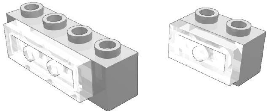
The fence does not present the offset nor the overlapping effect . The fence present an unexpected 7 LDU negative offset.
SNOT Examples
SNOT is not only a subject of study for itself but has practical uses. The followings chapters will covered some examples. One very frequently encountered SNOT building is the following, to create letterings (see chapter 3) or large windows for passenger trains. As you can see, it uses both stud-out and stud-in SNOT building :
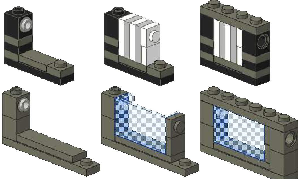
Employ of the 6:5 ratio is represented by this train front bumper, original idea by James Mathis.
SNOT 180
Some parts exist both in the normal and inverted version. For instance slope bricks, even some arches.
But some design will need the use of an inverted part which does not exist. Until now, SNOT has been limited to 90 degrees rotations. SNOT 180 allows you to invert parts.
SNOT 180 is then what you need.
2 x SNOT SNOT 180
SNOT 180 is sometimes as simple as combining two SNOT :
Combining two stud-out SNOT : these examples are 24 LDU high (1 brick)
Combining stud-in and stud-out SNOT
SNOT 180 parts
Some parts geometry allow direct inverted building, presenting tubes or studs on two opposed faces.
Studded SNOT 180 parts
The brick with studs on sides is used on official LEGO models for instance to create snotted undercarriage in Santa Fe’s sets. It is 40 LDU high (5 plates). The others bricks with studs on sides in the illustration are 20 LDU high
Two different type of 1x1 with clip exist. The left plate with clip, which is discontinued, is thinner than the new one. When stacking plates on both sides, the resulting width is respectively 20 LDU (one stud) and 24 LDU (one brick).
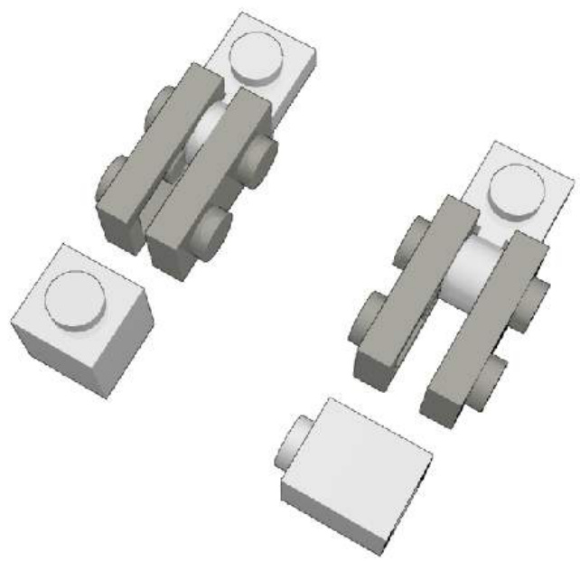
The Technic plates are passing through holes parts :
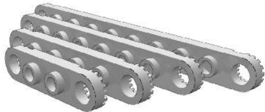
Technic bricks, lift arms, beams and ClickitTM ring are also examples of passing through holes parts but their thickness (12 and 20 LDU) is different from a multiple of a plate width.
The SNOT 180 technique has been originally named Knob inversion by Steve Barile. James Mathis has designed these applications :
Train cab window :
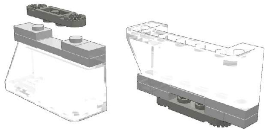
Oval train door window :
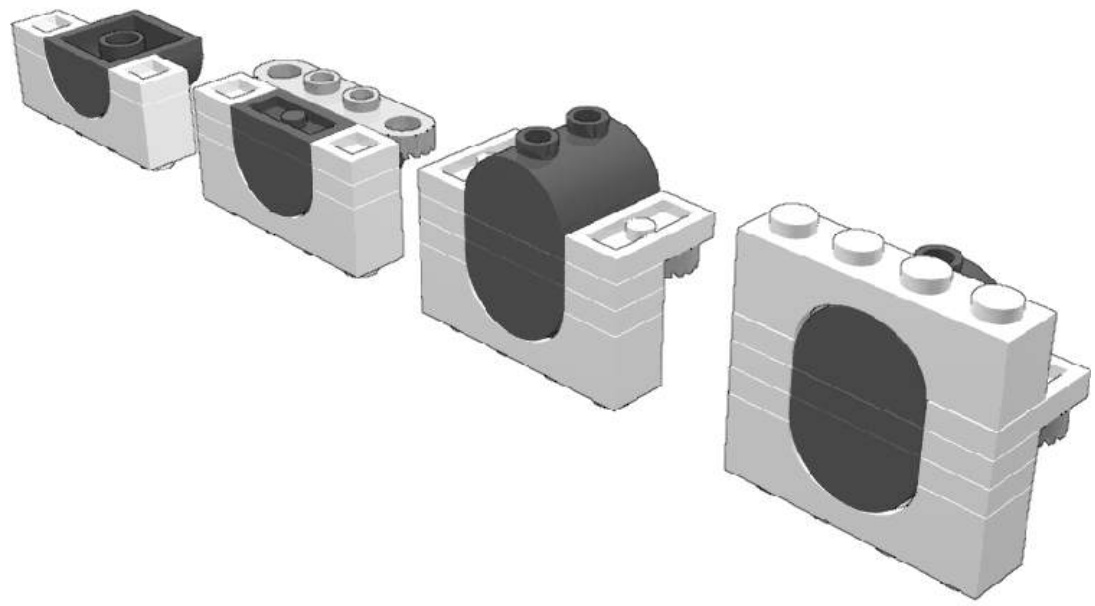
SNOT 180 connections
Some parts are part of a link system different from the stud and tube system and can be combined in an inverted way :
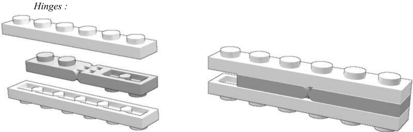
The resulting building is 24 LDU high. The same building is possible with plate and brick click hinges but then you will face respectively a 12 and 28 LDU height.
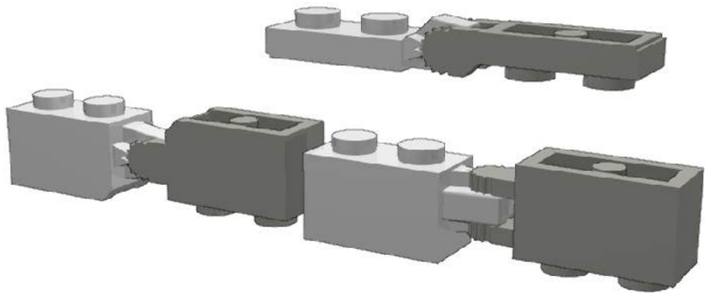
Clip and Bars :
Timothy Gould’s building :
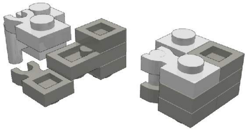
SNOT 180 with Technic parts
Axles
This building work only for bricks bigger than 1xn bricks.
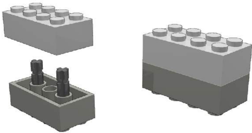
Half pins
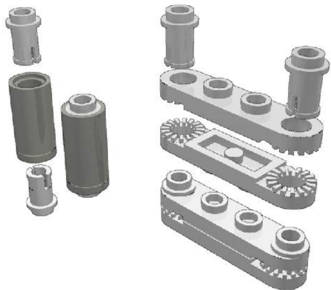
which are respectively 48 LDU high (2 bricks) and 16 LDU (2 plates) high (or 18 LDU if using the half pins studs and not the Technic plate ones).
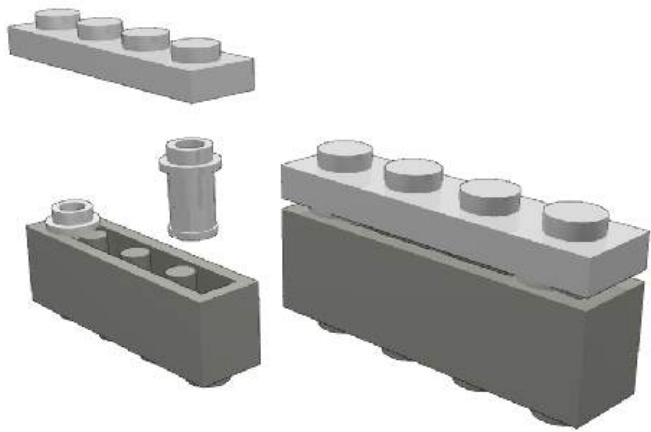
With a 34 LDU height.
Pins : with a 28 LDU height
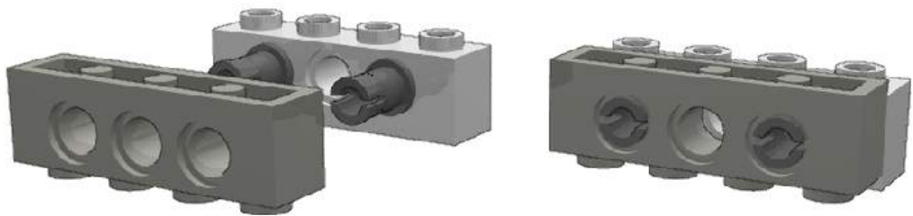
with a 50 LDU height
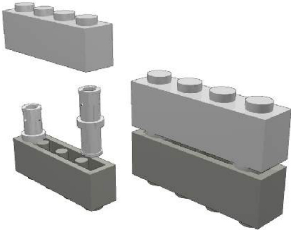
Others SNOT 180 buildings
Plate inversion with levers (control stick) is the thinnest SNOT 180 building with a 16 LDU height.
This building is limited to large plates. It can be reinforced by increasing the number of stick. It can also be improved using cut Technic tubing.
Pony ear technique and ToPLESs
The pony ear technique is a very particular SNOT building technique in this way that it applies to thin parts (plates, tiles) and requires no SNOT parts.
The original pony-ear technique consists in placing a 1x2 plate vertically between the studs of a plates. This building is used in classic official castle sets to represent ears of brick built horses.
As the plate is rotated to a vertical plan, it’s a SNOT technique even though it does not use specific SNOT parts. The pony-ear technique is quite limited by his definition and applications. The following ToPLESs technique is a natural enhancement.
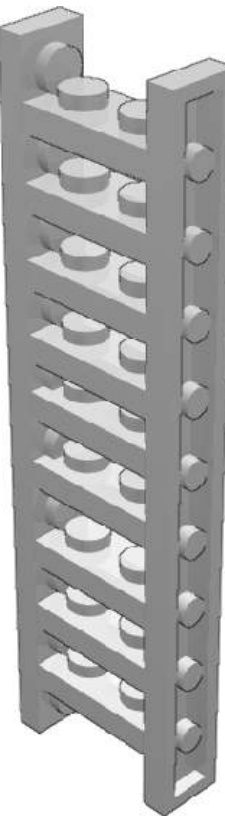
ToPLESs stands for Tile or Plate Located between Enough Studs. ToPLESs is an advanced building technique that has been developed directly from the pony ear technique. It has been theorized by Erik Amzallag. The following is entirely based on its presentation he made during a French AFOL meeting on 2004.
ToPLESs has appeared in official sets such 311, 609 and 613. In these official LEGO set, the use of this technique is very limited: only one or two plates or tiles are concerned. Adult fans use this technique to create thin walls, fences, ladders, beams, etc and more heavily as mechanical structure (footbridge, roller coaster).
ToPLESs is subdivided into P-LESs and T-LESs, where stands for Plate and T for Tile.
P-LESs present a major drawback. As studs are a bit thicker than 4LDU, the P-LESs stacking is in theory impossible due to overlapping effect. In practice, there are two situations. Whether the number of overlapping studs is low (for instance in the pony-ear technique) and then it cause no trouble, whether the overlapping studs is consequent and then it cause the plates to be bended. This drawback at least as one major advantage : the connection is very tight.
We can bring with two solution to the P-LESs drawback :
Offseting the studs are no more facing but alternate, so there is no more overlapping.
T-LESs : tiles are stud less plates, so there is no more overlapping. and the connection is still tough.
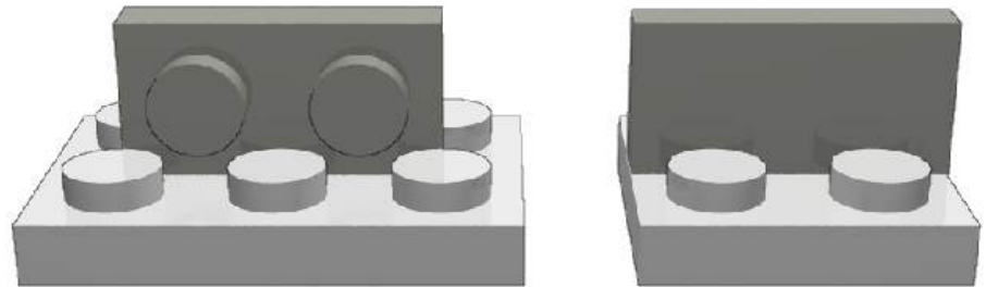
Various SNOT GSNOT
The G in GSNOT is for Gary (McIntire), the inventor of this building. At least, click hinge bricks have finally find a use.
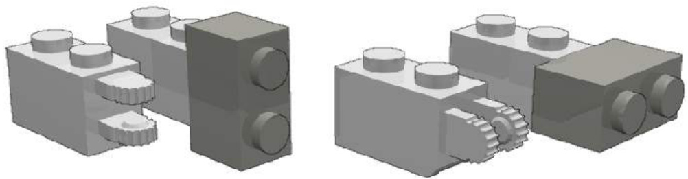
Combining three GSNOT :
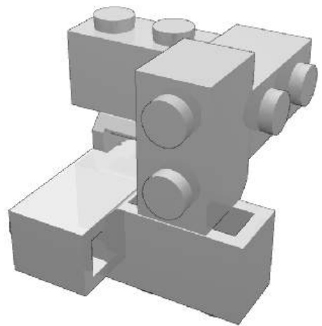
DSNOT
DSNOT is based on the hinge top part. The building is tight and allow rotation with friction. Further buildings could be imagined using hinge top part with other hollow stud part. As for GSNOT, DSNOT term has been coined by Jon Palmer and stands for Didier SNOT.
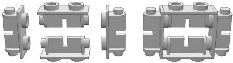
Offseting AZMEP
The following is partly based on Reinhard “Ben” Beneke presentation he has made during BrickWest 2003.
AZMEP is a german acronym (aus zwei mach eins Plättchen) for the half stud offset. That’s, with SNOT, the second most important advanced building technique. As for SNOT, it exists dedicated parts : AZMEP parts.
Among them, the most popular is certainly the jumper plate. So popular it has several names : center plate, jumper plate, jumper, 1x2 plate with one stud…
If we compare the jumper plate with the common 1x2 plate, we can see :
a) the top presents only one stud, which is centred: this allow AZMEP (half-stud offset) stacking.
b) this stud is hollowed : this allow regular stacking.
c) the underside is unchanged : the jumper plate behave this side like a regular 1x2 plate.
Regular and AZMEP stacking
Others tricks and parts allow to create AZMEP buildings :
Stud-to-tube trick : Rather than stacking the underside tubes between the studs in a classical way, you stack them directly on the studs. This technique works fine only if the plate you stack is bigger than the one she is piled on, because of edge effects.
Tube to hollow stud trick : This trick is very similar to the previous one and can be applied to narrower parts. It consists in stacking underside bars directly in the stud. Thank to Technic parts and some System parts, the hollow stud is widely available.
AZMEP Technic bricks In most Technic bricks, axle holes are placed, on the side, between the studs. That’s not the case in the two AZMEP Technic bricks where they are aligned, allowing AZMEP buildings :
AZMEP bar/arm and clip :
AZMEP is a tool to switch between the odd and even sizes in the LEGO building, for instance to create 7-wide trains or 5-wide cars.
Tenths-stud offset
AZMEP is a half-stud offset and is made possible by specific parts. It’s the most commonly used offset, but could we imagine a smaller size offset? Others parts present odd dimensional characteristics with 6 or 4 LDU offset. Among them, these SNOT parts.
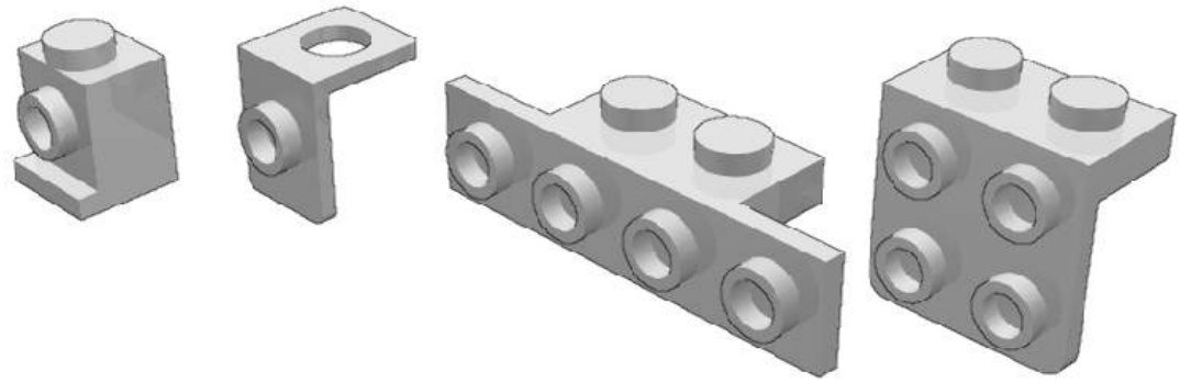
These offsets and stud-out SNOT allow tenths-stud (2 LDU) offset. Jason Railton has listed an exhaustive buildings collection similar to this one :

The jumper plate provides a 10 LDU offset, SNOTted plates provide an 8 LDU offset and the headlight brick provide a 4 LDU offset. The following illustration will help you in building the increasing offset.
The original building by Jason Railton uses hinges and brackets.
Continue offset
Until then, we have dealt with discrete (in the mathematical meaning) offsets half-stud, tenths-stud. Even though LEGO is mainly based on discrete system, some parts allow continue offsets :
Bars / Arms and Clips
Technic Axles and Bricks
Marakoeschtra’s wall
Real brick built walls present a typical pattern where bricks alternate with thin joints. Could we recreate this pattern with LEGO parts ? The combination of SNOT and continue offset leads to an elegant (and parts consuming!) solution :
The 1x2 tile have this specificity they don’t have underside tube. They can freely slip on the studs, allowing a continue offset. This specificity is used for this wall, where the tiles are stacked on the studs with an offset of 5 or . The vertical joints are 5 LDU when horizontal ones are 4 LDU thick.
Alternative buildings :
Letterings Introduction
You may need to put some brand, name (short text) or graffiti on the sides of your rolling stocks, coaches or engines, shuttles and fighters or buildings. Let’s study some of the various ways to perform such decoration.
Stud-out mosaics
You can use a “stud-out” mosaic technique. The LEGO Company proposes a font based in such technique on the 226 idea book.

Smaller font based on this technique can be achieved. They are easy to use and all the letters and figures can be represented. But this font is not really small. For instance, the following font is 100LDU high and the bars of letters are 20LDU wide. This technique is not an advanced one.
100LDU sized upper case letters and figures
In some case, you could satisfy yourself with smaller letters and figures:
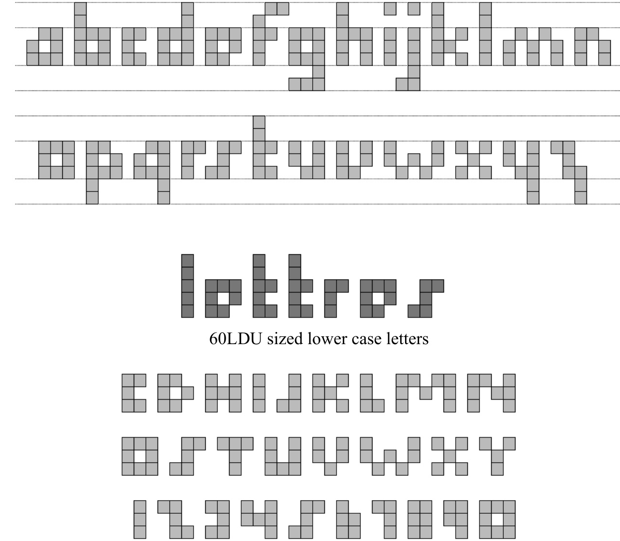
60LDU sized upper case letters
These latter examples show some 60LDU sized letters can be achieved but are not really aesthetically satisfying. Then, we need to scale down the building.
Stud-up mosaic
Stud-up (classical way of stacking plates and bricks) mosaics letters are smaller. (40 LDU)
The structure of this font is identical to the previous 100LDU stud-out font.
The horizontal bars of the letters are 8LDU wide instead of 20. The vertical bar of letters is still 20LDU wide. As a consequence, letters may look wider than tall or bolded.
Both stud-out and stud-up fonts particularly fit well with non-rounded and non-diagonal letters such : E,F,H,I,L and T but also with figures and rounded letters which can be squared (A,C,G,J,O,P,S,U). Some good looking results can be achieved with diagonal letters such N and X.
Stud-up letters are smaller, but it’s not a great advantage because they are only vertically shortened. That does not allow in practice a better (smoother) dithering. However, this is sufficient to apply into some LEGO creations.
James Mathis’ SBB pattern and CFF pattern on Swiss Re44 engine.
SNOTized mosaic letters
This kind of font consists of a rotated stud-up mosaic letters. Due to the rotation, the horizontal bar of the letters are then 20LDU wide and the vertical ones 8LDU wide. The font is 80LDU tall. As you can see in the pictures below, this lettering implies the use of SNOT Techniques. In fact, that’s a direct application of the basic SNOT techniques.
Mathis letters
The Mathis letters are an improvement to the SNOTized letters, which lead to a 56LDU tall font. Mathis improvement consists of creating up and down 8LDU thick lines without adding SNOT building difficulties.
Examples of Mathis letters
Mathis font pros are the small size and thin bars of the letters. But the font is not complete, for instance you can’t realize the letters with mid level bars such the B, F , H, P, R or A and E. So our goal is not totally achieved.
SNOT font
These letters present both vertical and horizontal 8LDU thick bars but are harder to build. SNOT skills are required. The great advantage with SNOT building is that letters with mid-level bars can be easily represented contrary to Mathis letters. The building structure is based on the 5:2 fundamental SNOT geometry ratio. A drawback to SNOT lettering is that the letters are, at least, 2L deep. This may prevent you from using such a technique in 6-wide train applications or internally detailed models. At least this technique is well appreciated by adult builders:
Chips trailer by Jeff Van Widen
Diagonal striping
Real locomotives, rolling stock, trucks present a great variety of liveries. To recreate this colour scheme in LEGO models is challenging. Focusing on diagonal striping, using slope bricks is an answer at first glance. They are available in large variety of colours, and with their inverted counterparts in various angle values.
Slope bricks striping One plate height (8 LDU) offset.
Unfortunately, normal and inverted slopes can not be placed side by side in the classical way, because of an overlapping effect. The commonly used answer to the overlapping effect is the use of one plate height offset. Some rapid theoretical calculations show that the gaps between slope bricks vary from 3.6 to . They are reasonably good for LEGO models.
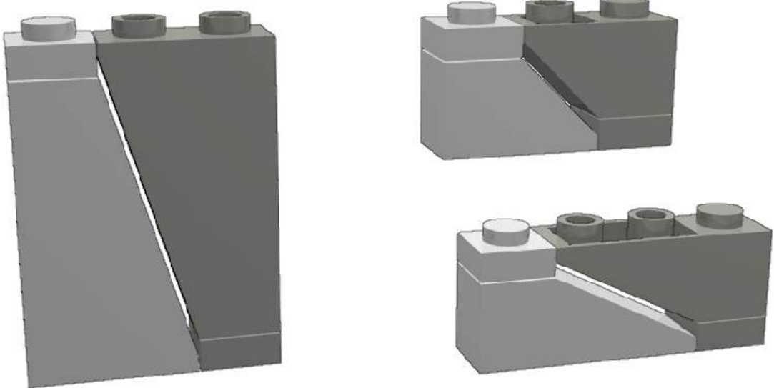
One plate height offsets
Half-stud offset
If the two slope bricks are placed side by side with a half-stud offset, the gaps are different.
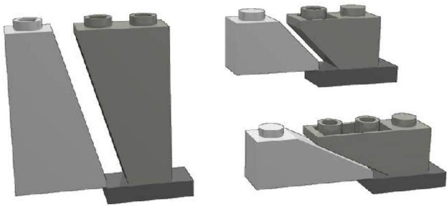
In the case of the 1x2x1 slopes the gap is higher, in the case of the 1x3x1 slopes, the gap is reduced and negligible, in the case of the 1x2x3 slopes the gap is higher but allows the placement of a 1x4 tile.
This technique first seen on the TGV locomotive by Xavier Viallefont has the main advantage of allowing three colours scheme and/or fine diagonal striping.
This technique has also been used to build Tudor style house decorative walls by Lenny Hoffman. The 1x4 tile is floating but you can use two tiles and attached them in the back.
A similar technique, using the free space between parts to fill it with floating tiles, has been developed by James Brink to create five wide windows, again, in the Tudor style.
Micro-striping
Micro-striping techniques allow to create stripe coloured shape with a width of less than the height of one plate, i.e. less than 8 LDU. Micro-striping is an original idea from Steve Barile on 2002 developed by James Mathis in the LEGO Trains theme.
The micro-striping is possible thanks to parts with thin component. Micro-striping then will often require SNOT or/and offset mounting. Thin parts are components of flags, brick hinges top, brackets, fences, panels and baseplates. Most of them are 4 LDU thin. Brick hinges top are 2 LDU thin, the fences are 6 LDU.
Thin parts
Micro-striping examples
Top hinges brick micro-striping That’s the simplest micro-striping technique, with no SNOT or offset building. Be careful that the lowest stripe is only 22 LDU high instead of 24.
SNOT mounted bracket micro-striping This building requires SNOT, the lower stripe is 20 LDU high and there is a little front offset. This micro-striping building’s length is at least a multiple of 4L.
SNOT mounted bracket micro-striping This building is easier and his length is a multiple of 2. The lower stripe can be as low as 8 LDU but the total height present an offset of 4 LDU.

Studs Not In a Row (SNIR)
Large parts – baseplates for instance - have regularly spaced studs on their top, shaping an orthogonal matrix. The space between the studs is 1L. Two 1x1 parts placed side by side on a base plate just leave a very small margin between them: the 1x1 parts placed side by side are prevent from being nonorthogonally placed. On SNIR techniques, parts are placed not simply side by side but in diagonal, to obtain a row not in the classical way.
SNIR 45
Assuming the dimension of 1x1 part and stud diameter, individual 1x1 part in this matrix can be nonorthogonally placed, in any angle as shown in the followings illustrations. Some figures :
- The distance between two studs is 1L,
- the gap between two studs is 0.4L,
- the diagonal dimension of a 1x1 part is 1.414L (square root of 2L).
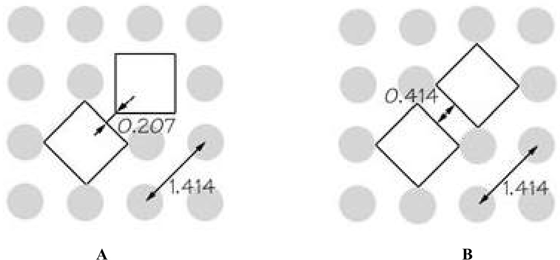
The B shape is a new and innovative Studs Not In a Row (SNIR) building technique. Some perfect vertically fitting and stud less upward side is possible using a 1x1 tile stacked on two 1x1 plates. The three plates (two plates and one stud less plate - tile) are high. It equal the tile width (1L) added with a stud height .
This technique has been originnally developped by Erik Amzallag
SNIR 27
This SNIR technique has been developped by Reinhard Beneke. It allows to build a wall at an angle of about to the baseplate grid of studs. This angle is performed using jumper plate AZMEP technique. The 1x1 elements which the wall are made of (here bricks) may also be slightly turned to create of less regular shape.
Mixed cylinder curving
LEGO parts are not meant to be used to create nicely curved surfaces and you will obtain a pixelated looking. Of course you could use special purpose parts – rounded ones – but with limited choices : small diameter, colours restriction..
Larger smooth curved walls can be obtained, without stress, by mixing small regular parts (1x2 to 1x4) with 1x1 round parts (plates or bricks). Eric Brok has coined the “mixed cylinder curving” name to this building technique. This technique is very part consuming.
Thank to moulding tolerances, very big radius curved walls can be obtained by stressing a bit walls made of 1x2 parts.
-WHy THIS GAP?
TO FIND OUT, LET’S ADD A FEW MORE PARTS. IT TURNS OUT THAT IT’S ANOTHER CLEVER DECISION, WITH THE MAGIC FORMULA IN MIND AGAIN.
SAME HEIGHT!
THAT’S ALL INTERESTING IN THEORY, BUT HOW CAN WE PUT THIS KNOWLEDGE TO USE? THIS BOOK IS FULL OF EXAMPLES OF THESE TECHNIQUES. HERE ARE A FEW:
I USED A CLIP TRICK (LIKE THE ONE SHOWN ABOVE)TO ATTACH THE WINDSHIELD OF THE MULTI-PURPOSE TRUCK.
IN THE MUSCLE CAR’S BACKLIGHT,THEMAGICFORMULAISCLEARLYVISIBLE!
5 PLATES =2 STUDS
NOW THAT YOU UNDERSTAND THESE BASIC TECHNIQUES, LET’S START PUTTING THEM INTO PRACTICE.
KEEP YOUR EYES OPEN FOR THE MAGIC FORMULA!
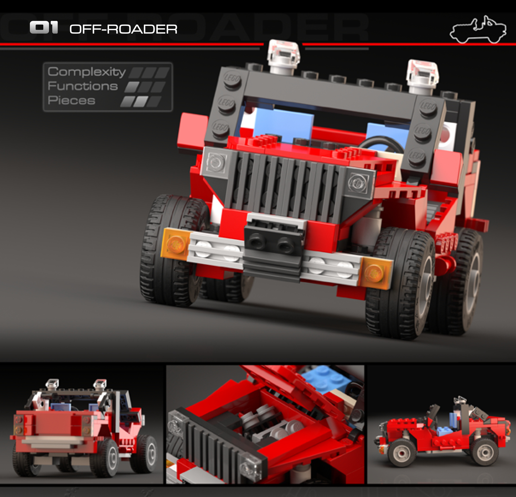
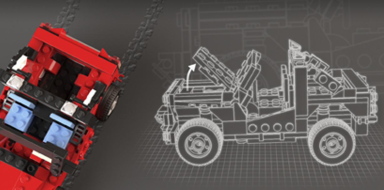
OFF-ROADER
Design notes: wide wheelbase, high clearance,exposedshockabsorbers, front-bumper winch, spotlights
Technical specifications: Dimensions (I×w x h): 20×10 ×10 studs Wheelbase: 11 studs Axlewidth front/rear: 10/10 studs
Features: hinged hood, V4 engine, rear accessoryclips
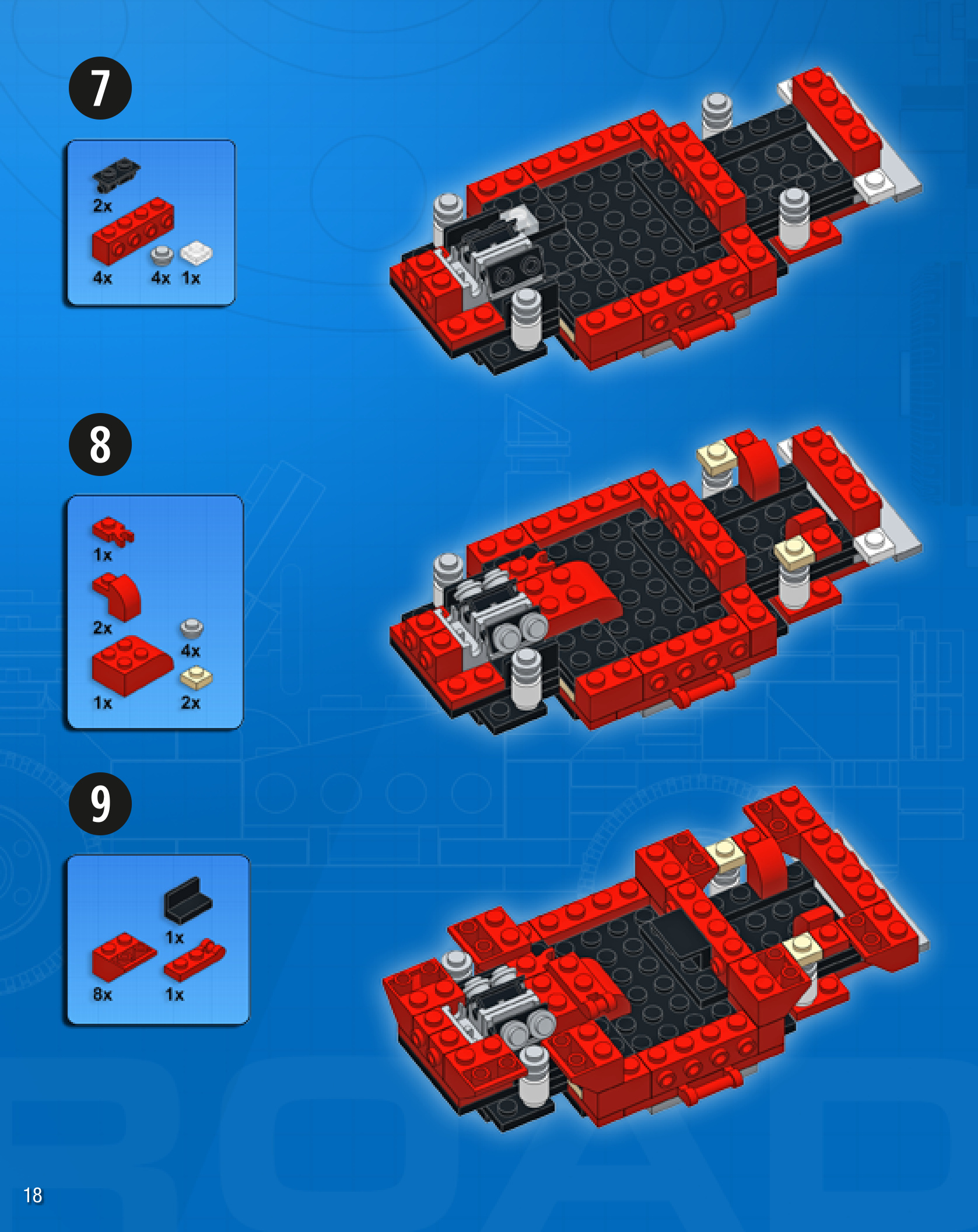
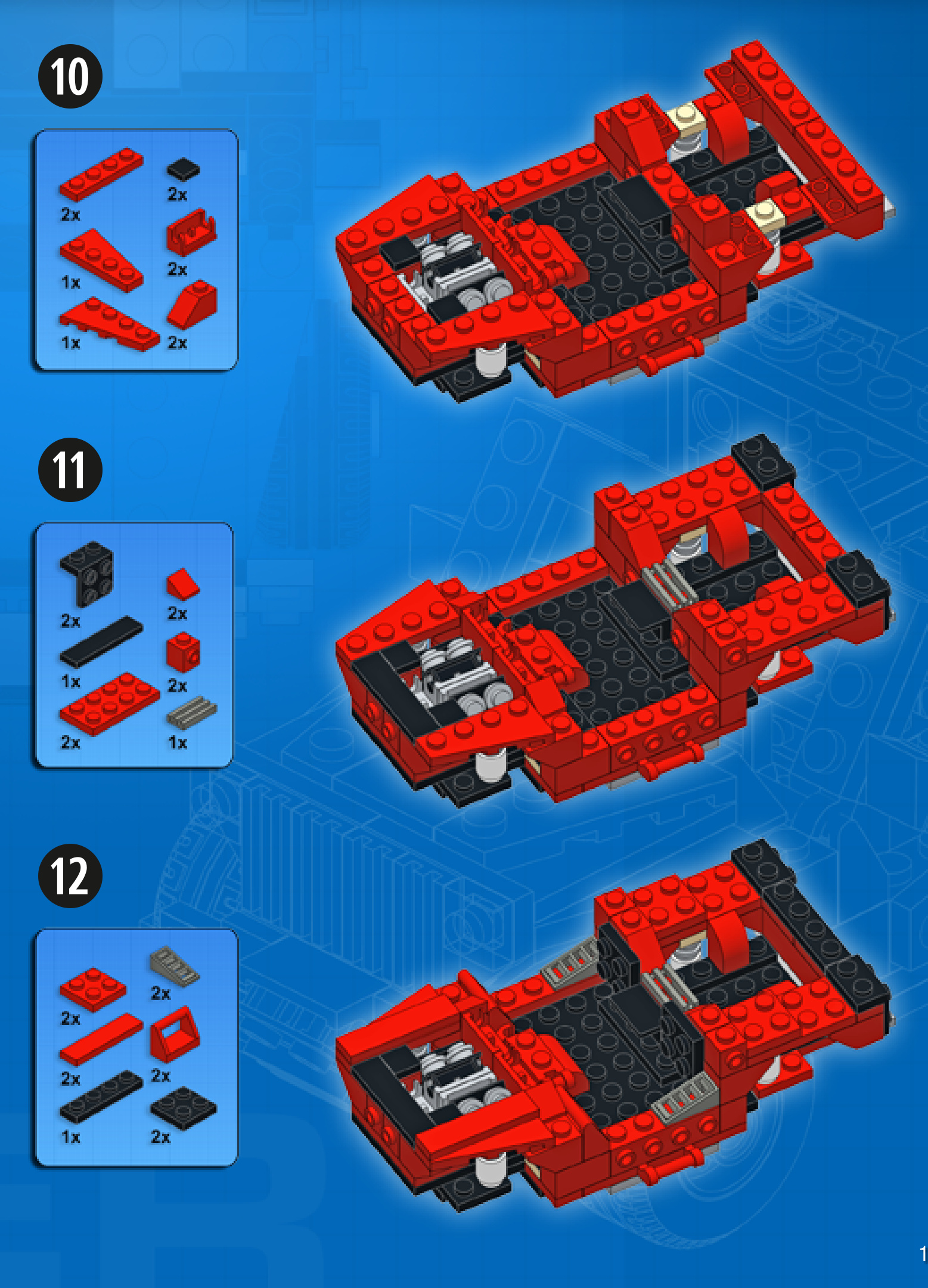
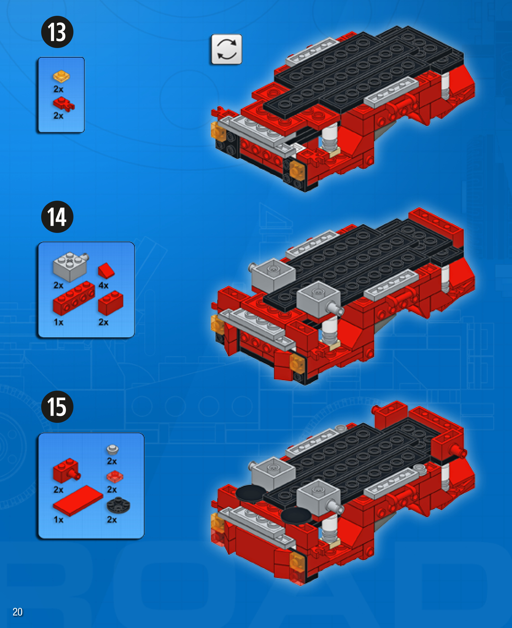
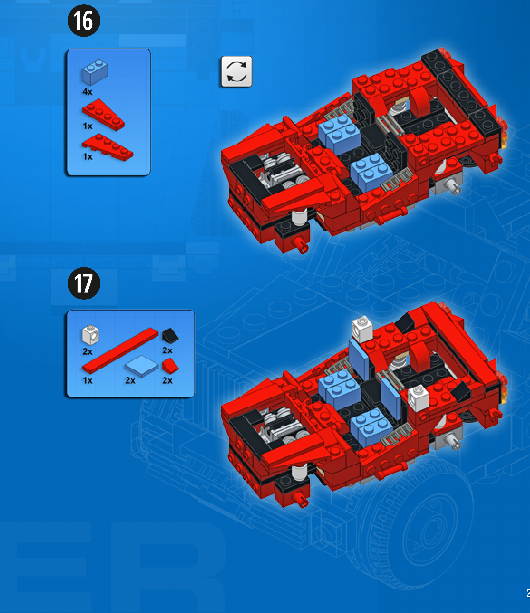
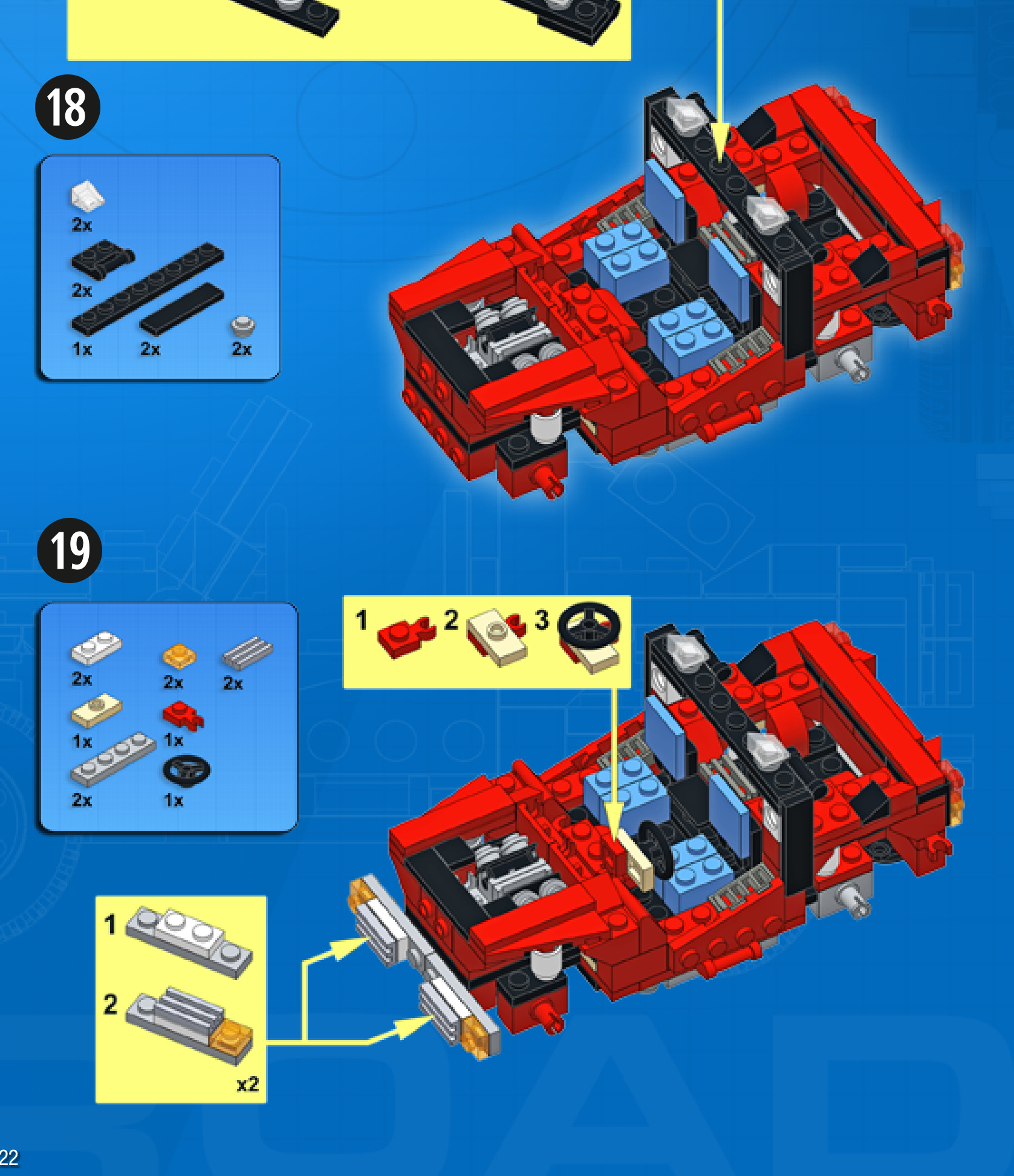
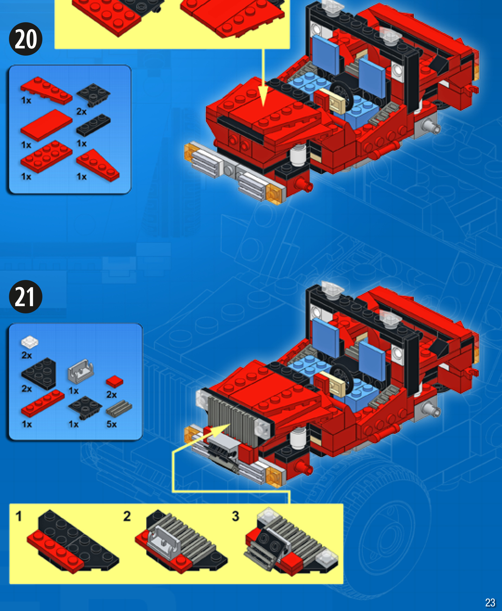
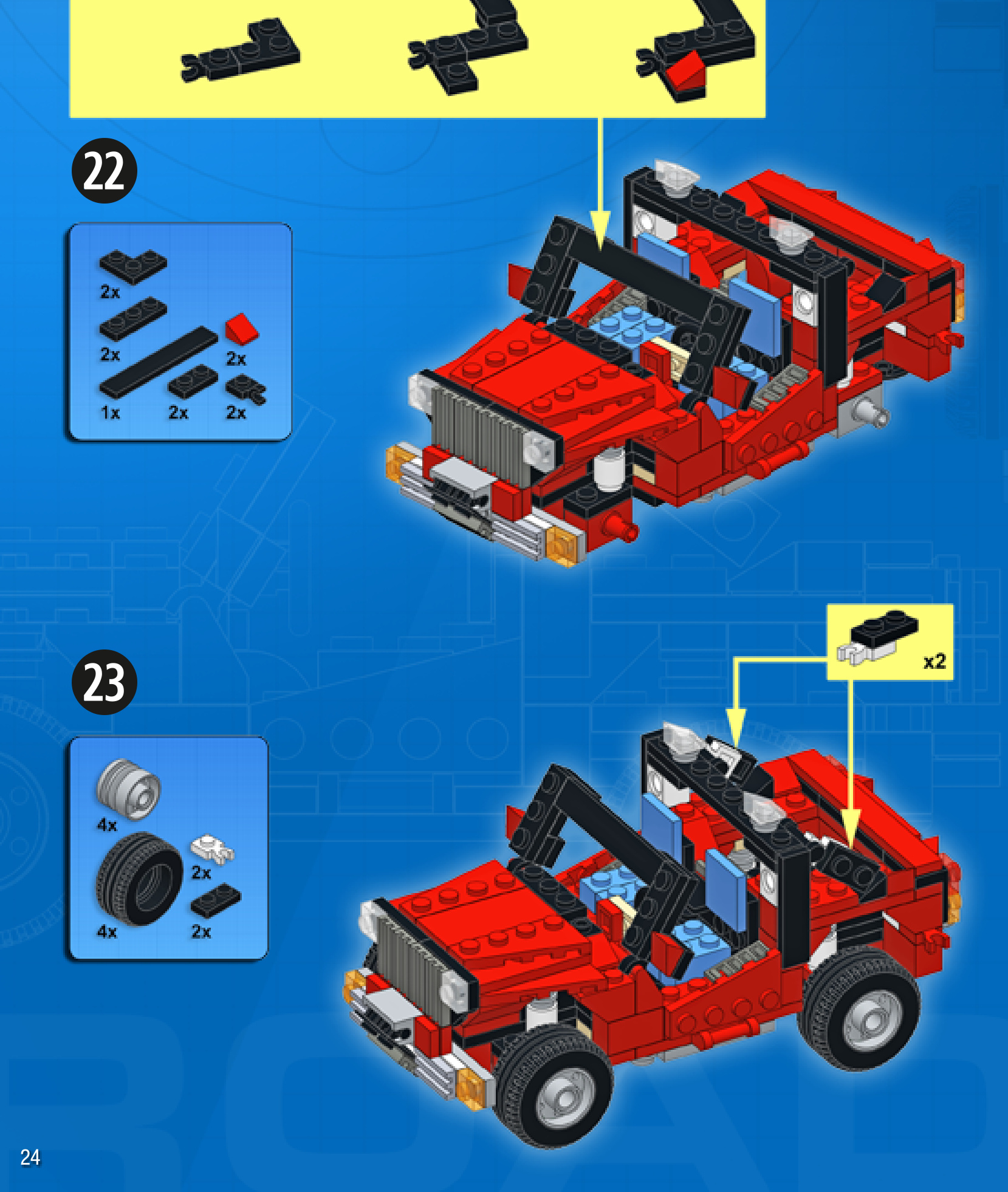
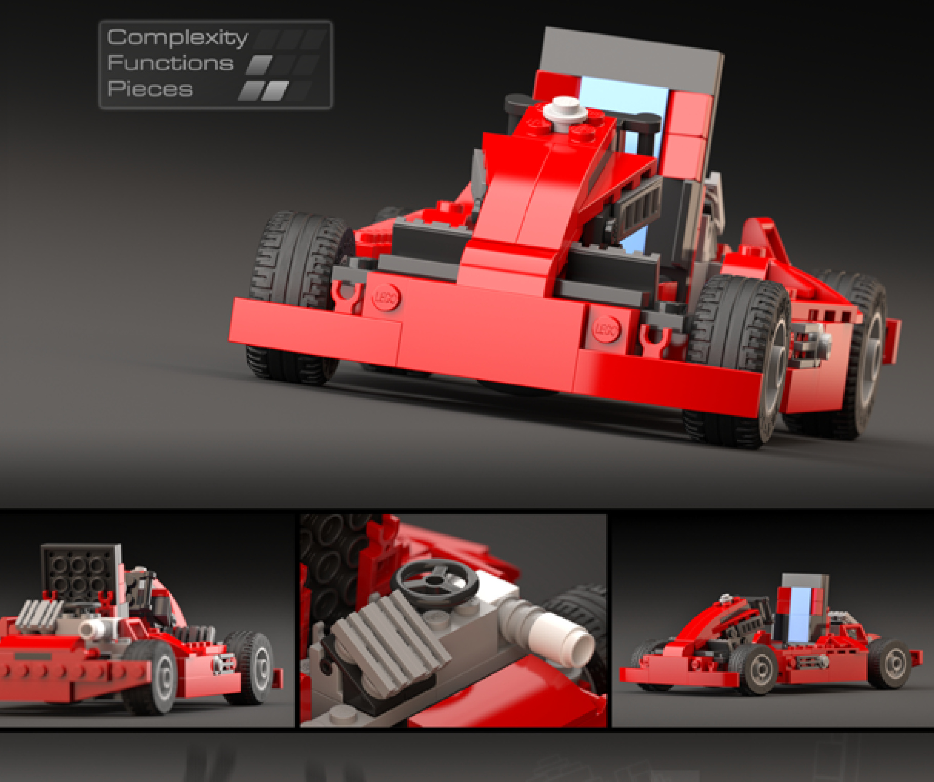
GO-KART
Design notes: wide and low chassis, single-cylinder engine, large seat, small wheels, gasandbrakepedals
Technical specifications: Dimensions (lxw× h): 21×12×9 studs Wheelbase: 14 studs Axle width front/rear: 12/12 studs
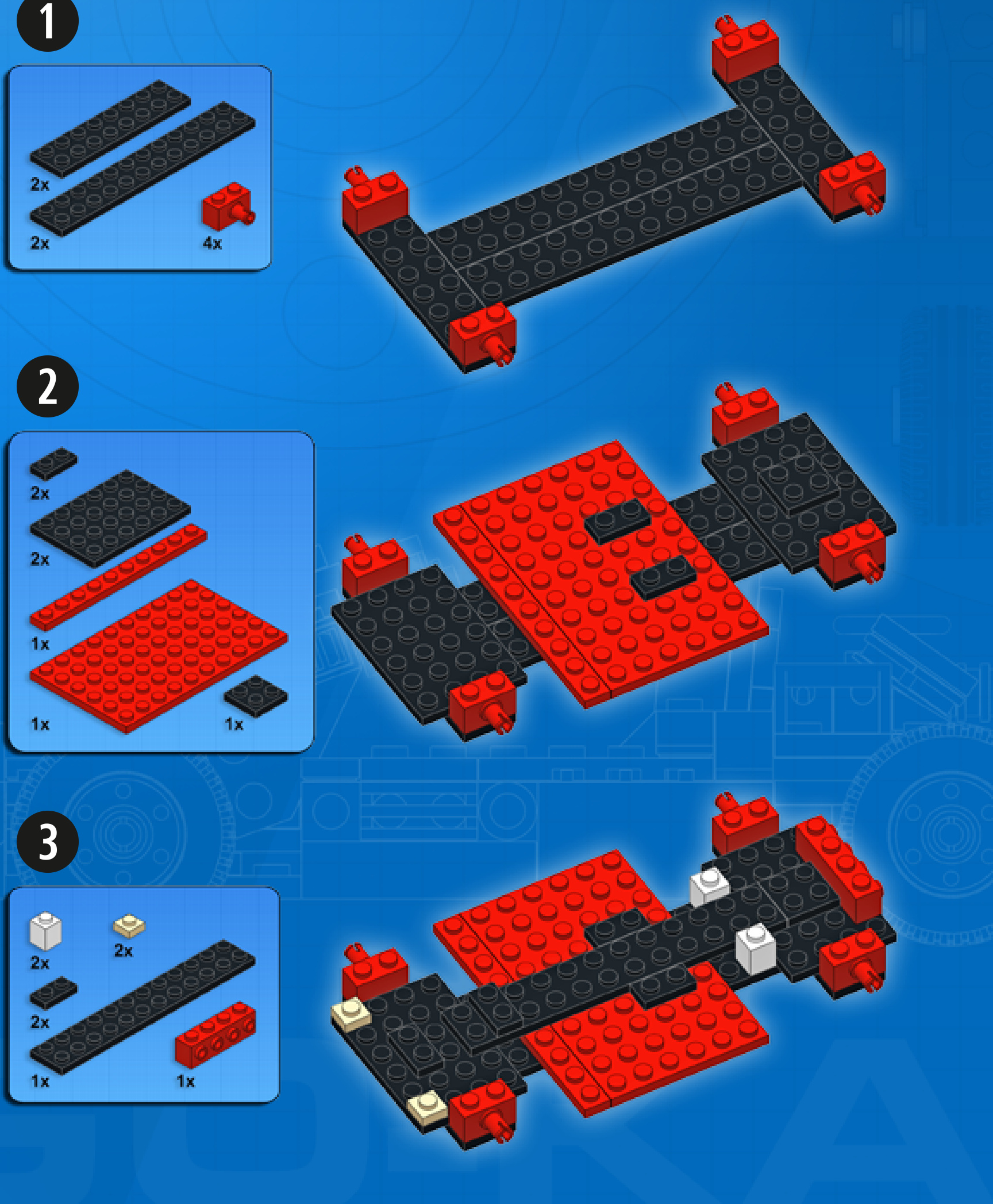
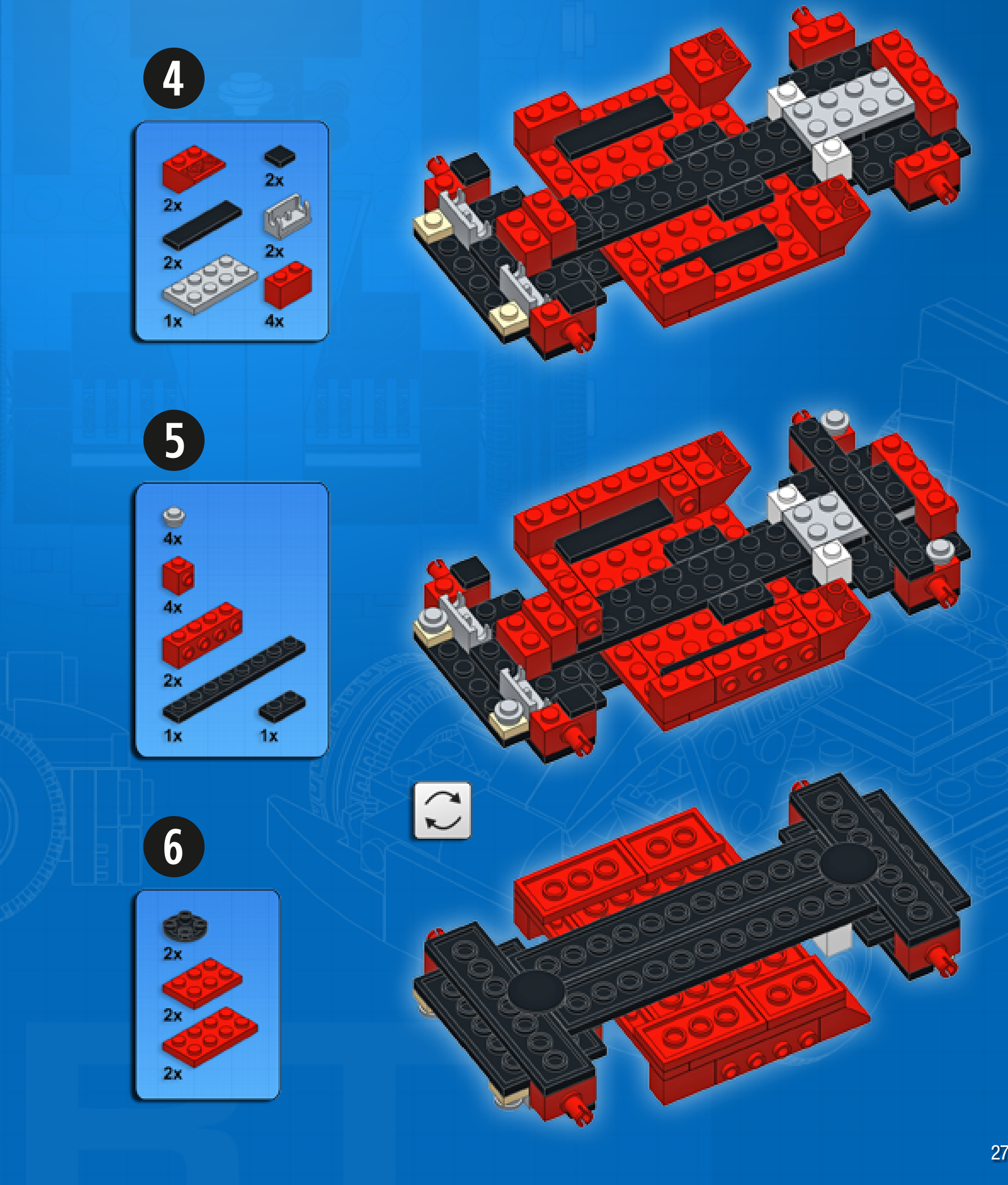
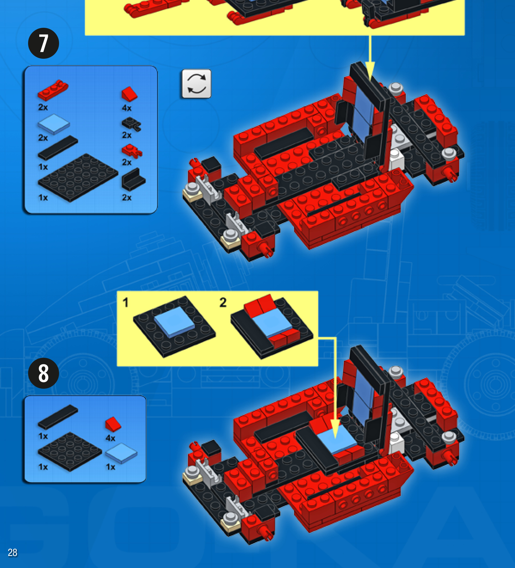
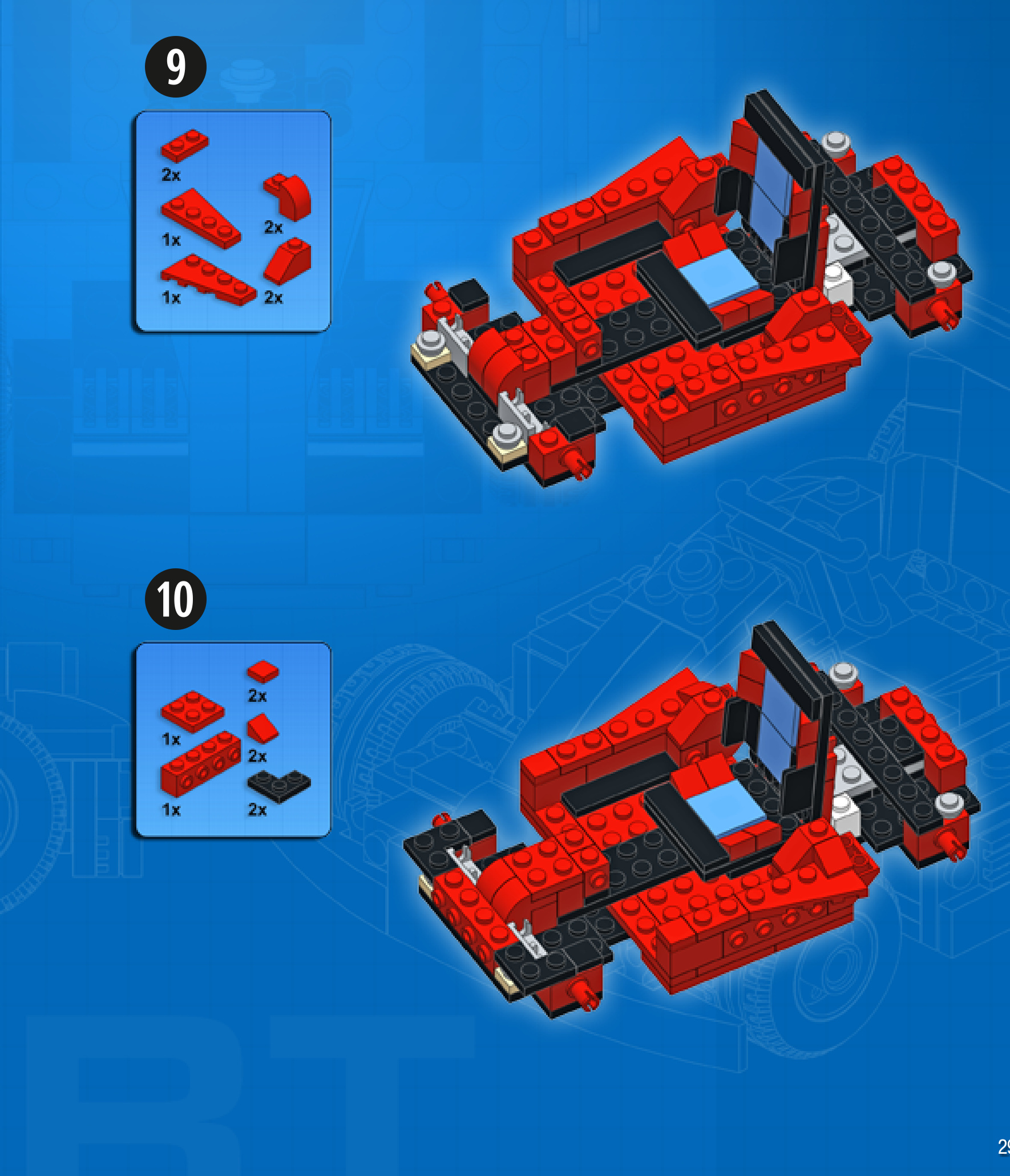
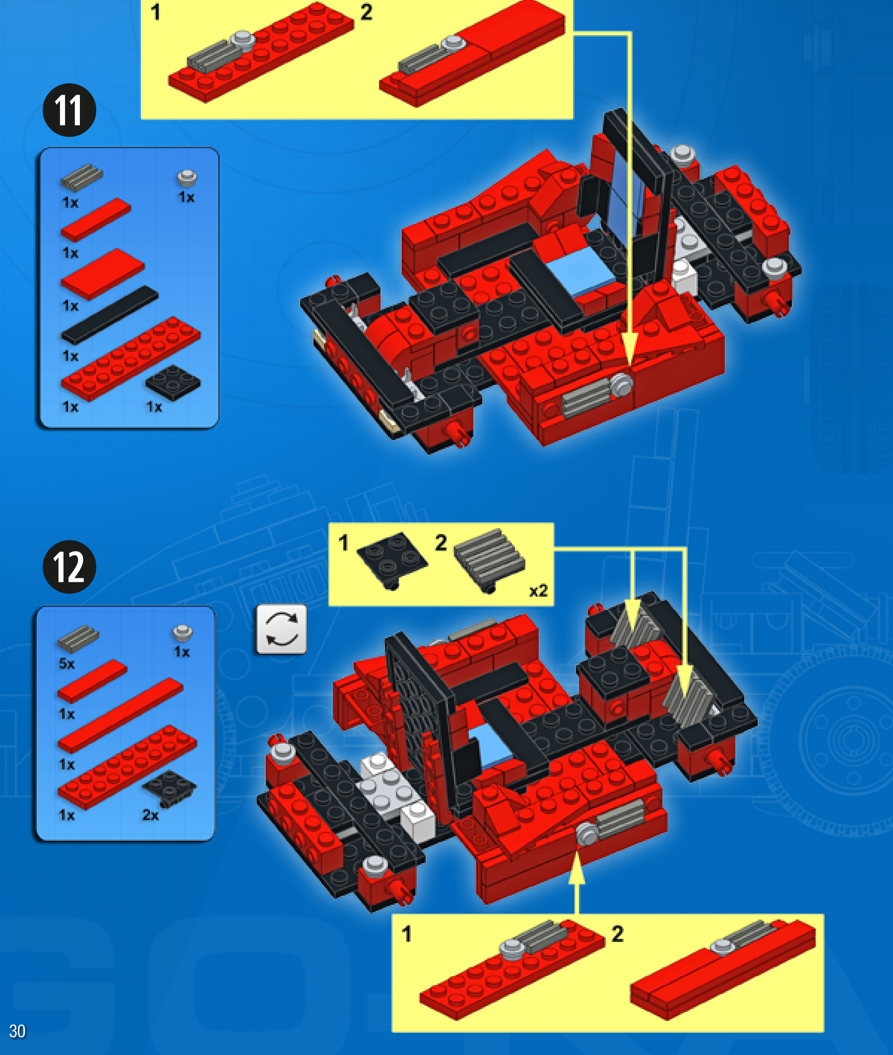
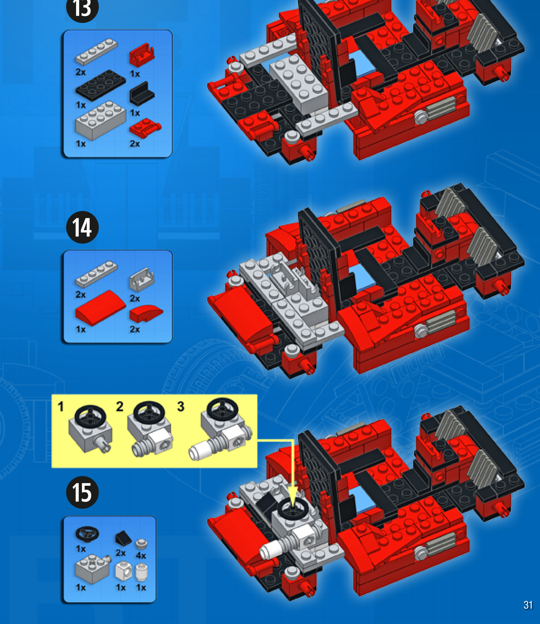
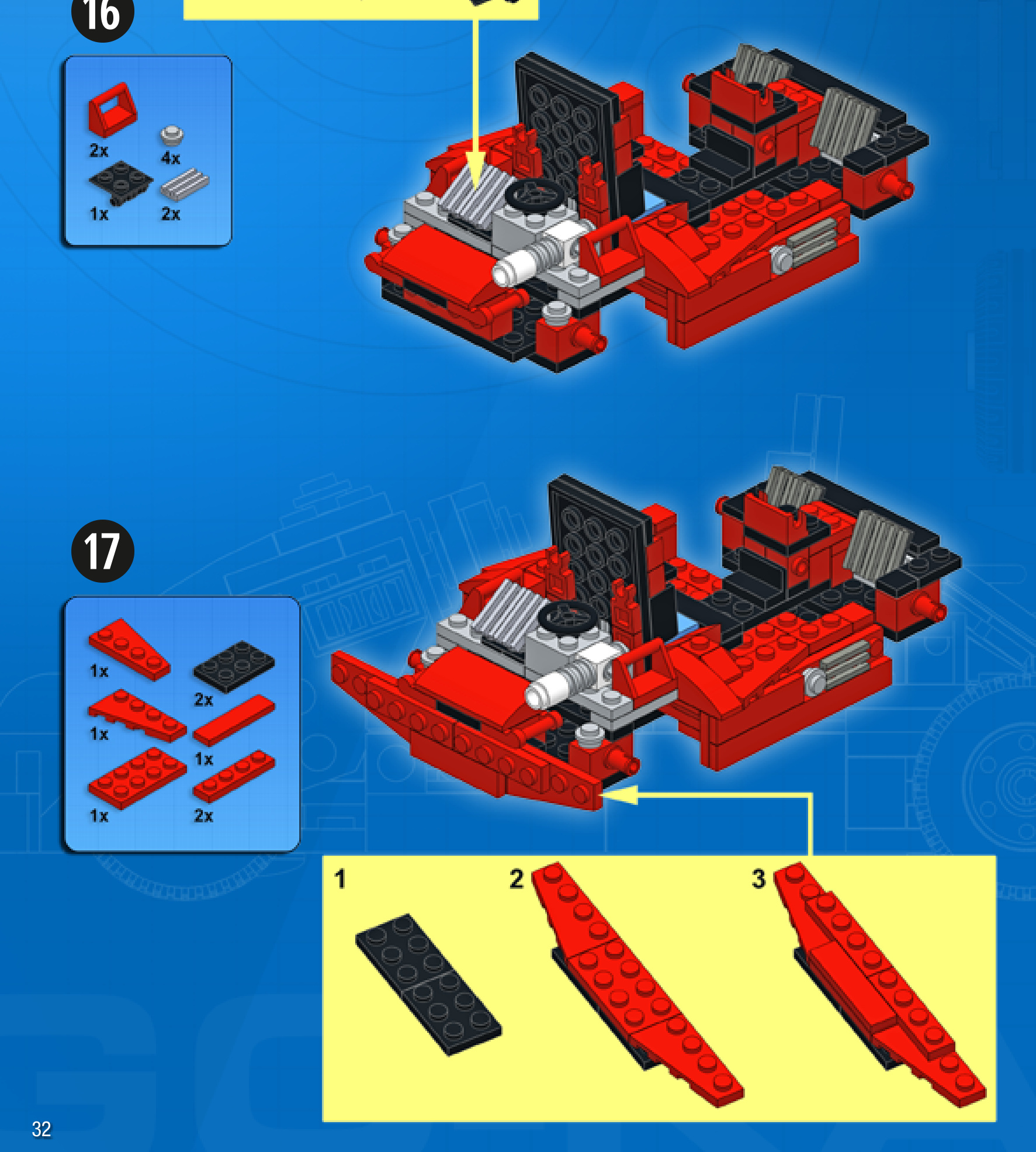
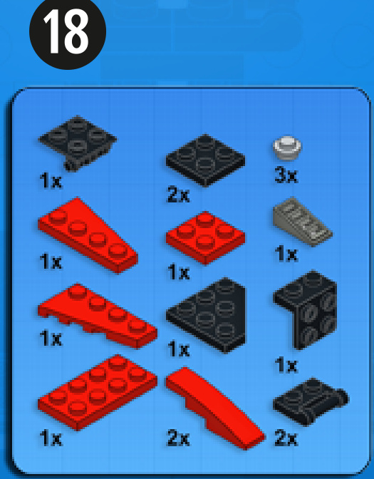
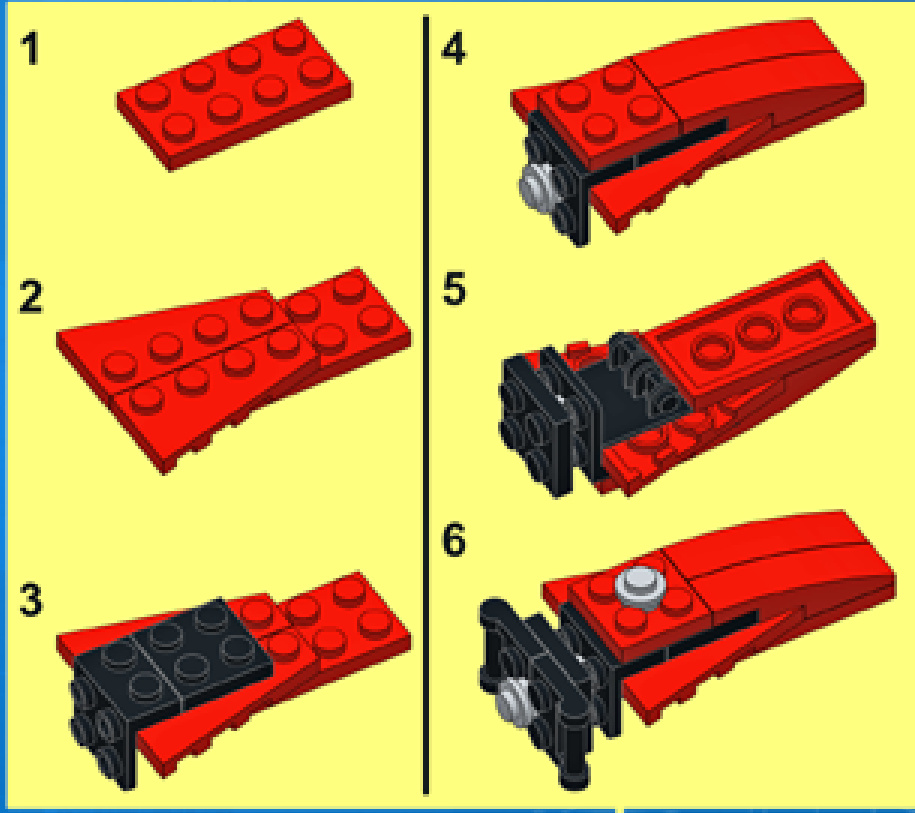
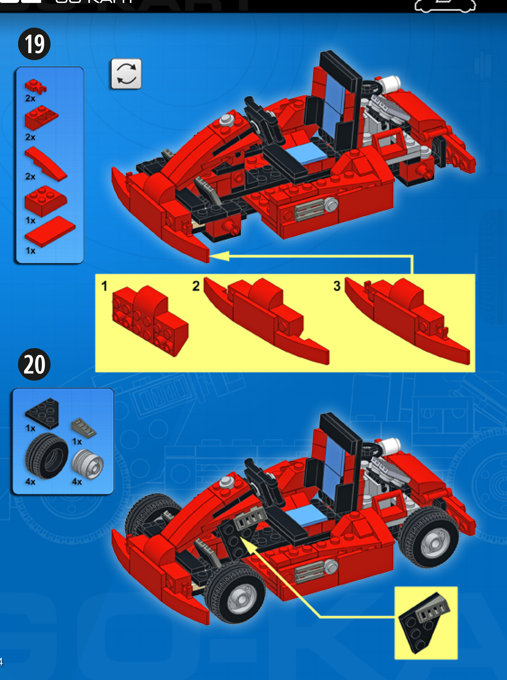
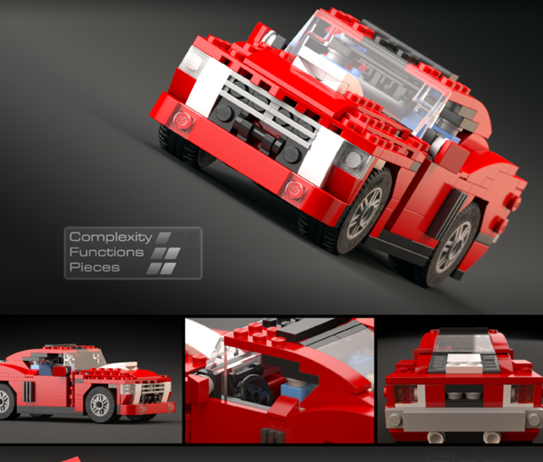
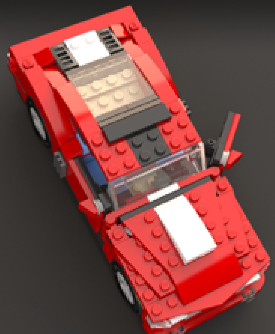
MUSCLE CAR
Design notes: fastback body design, hood scoop, exposed exhaust pipes
Technical specifications: Dimensions (lxw× h): 21×10×8 studs Wheelbase: 12 studs Axle width front/rear: 8/8 studs
Features: opening doors
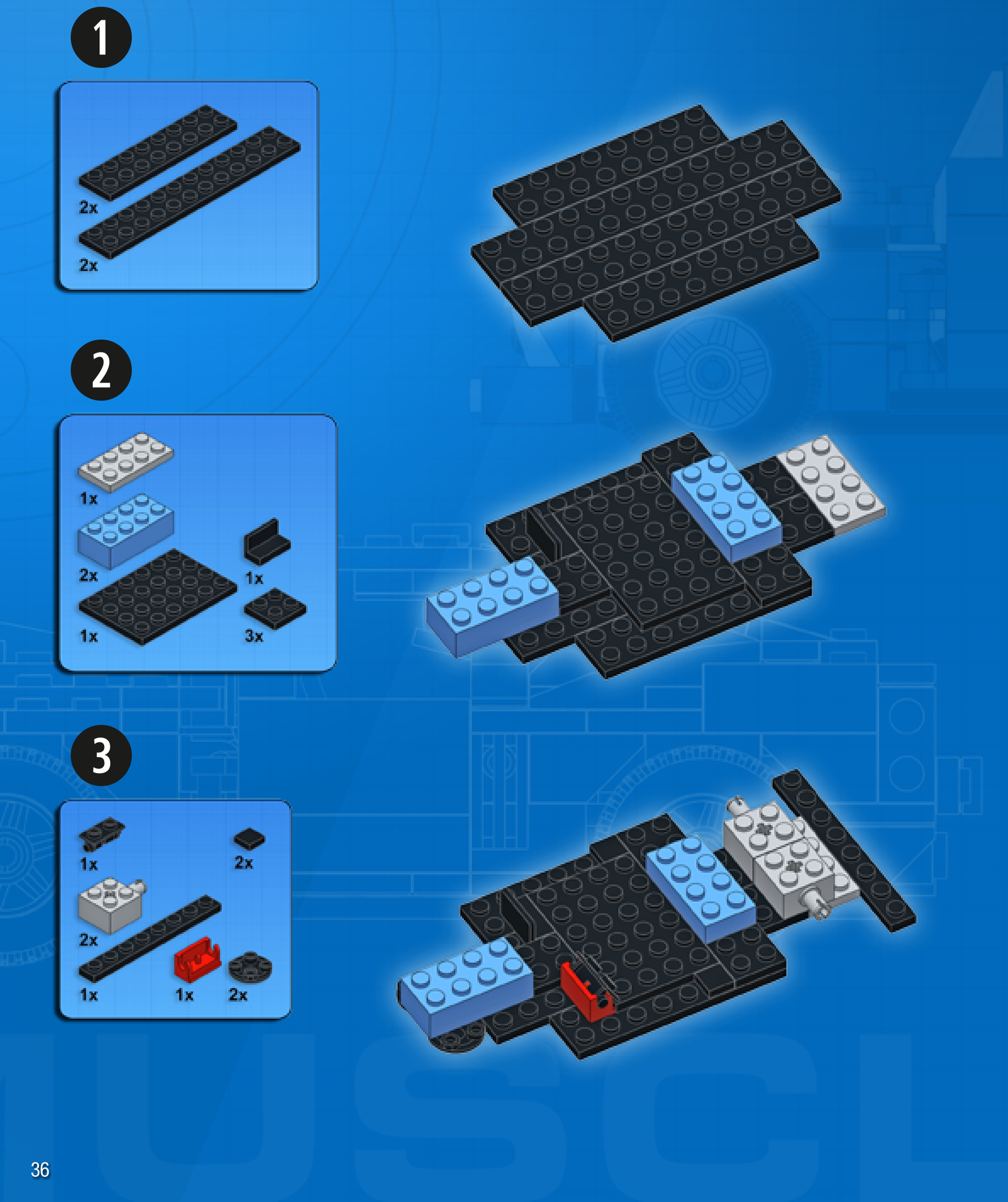
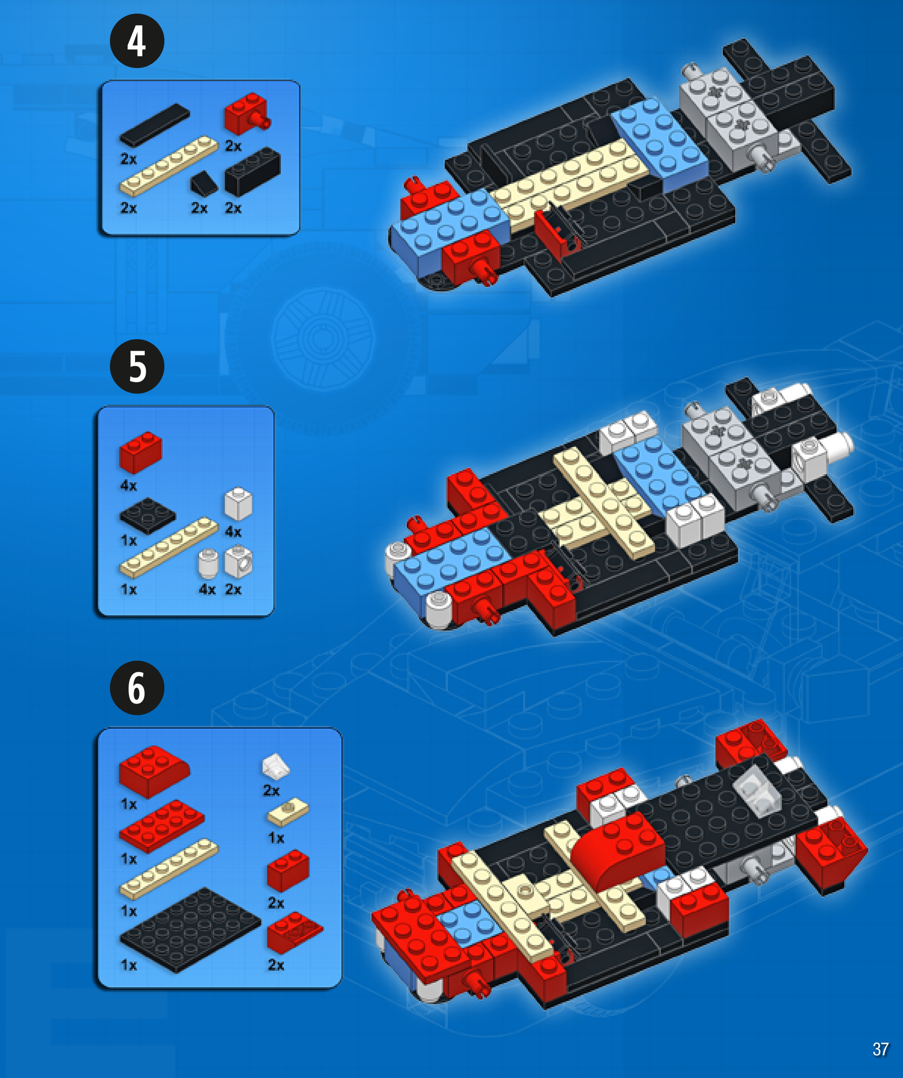
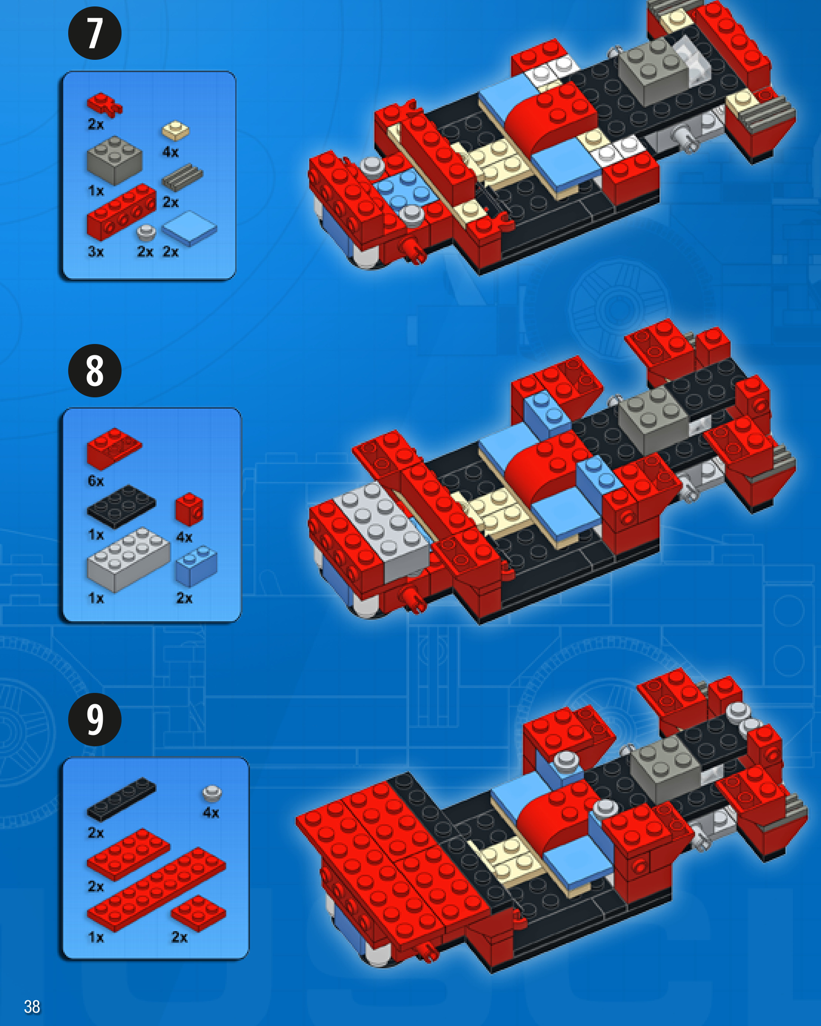
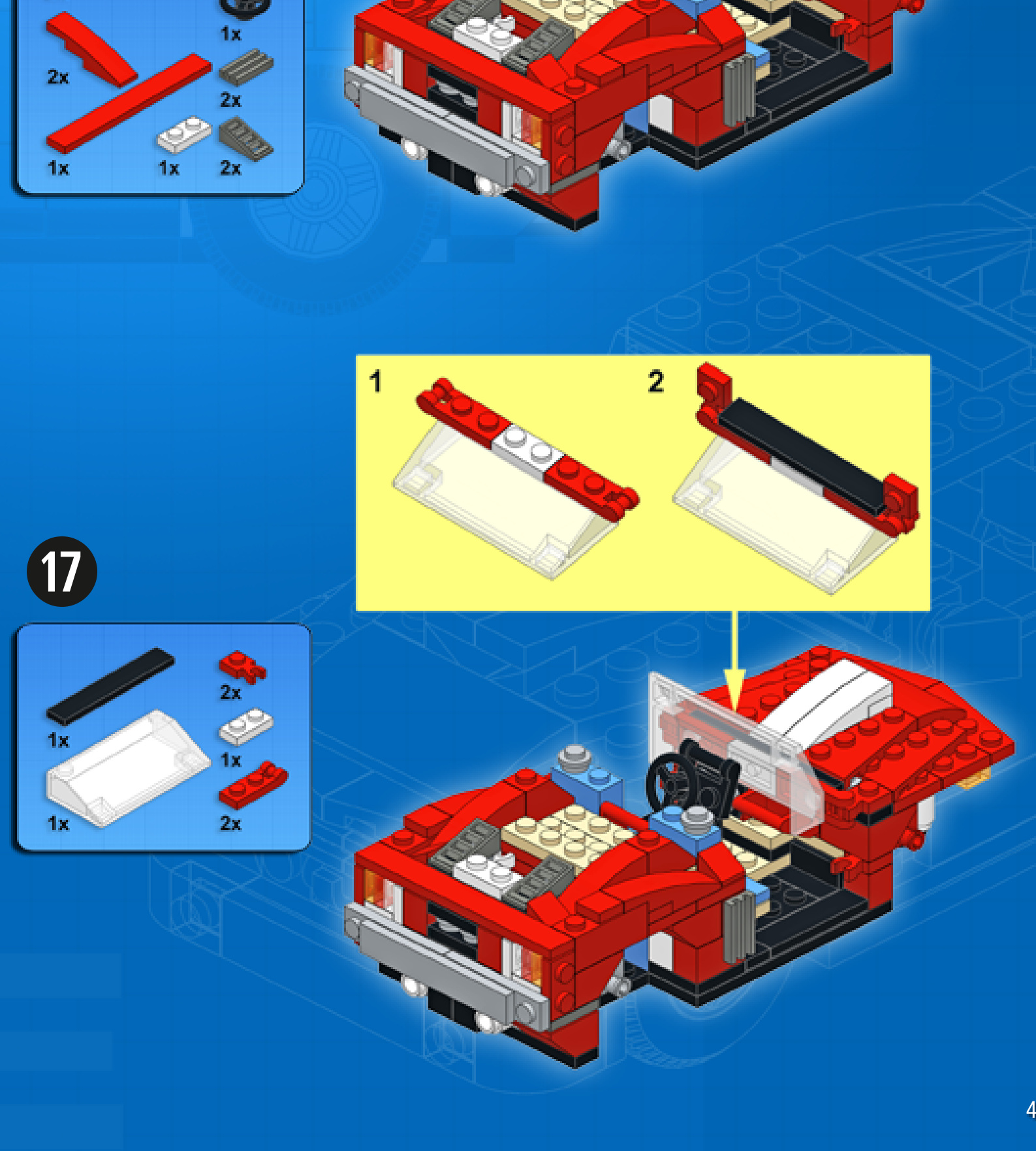
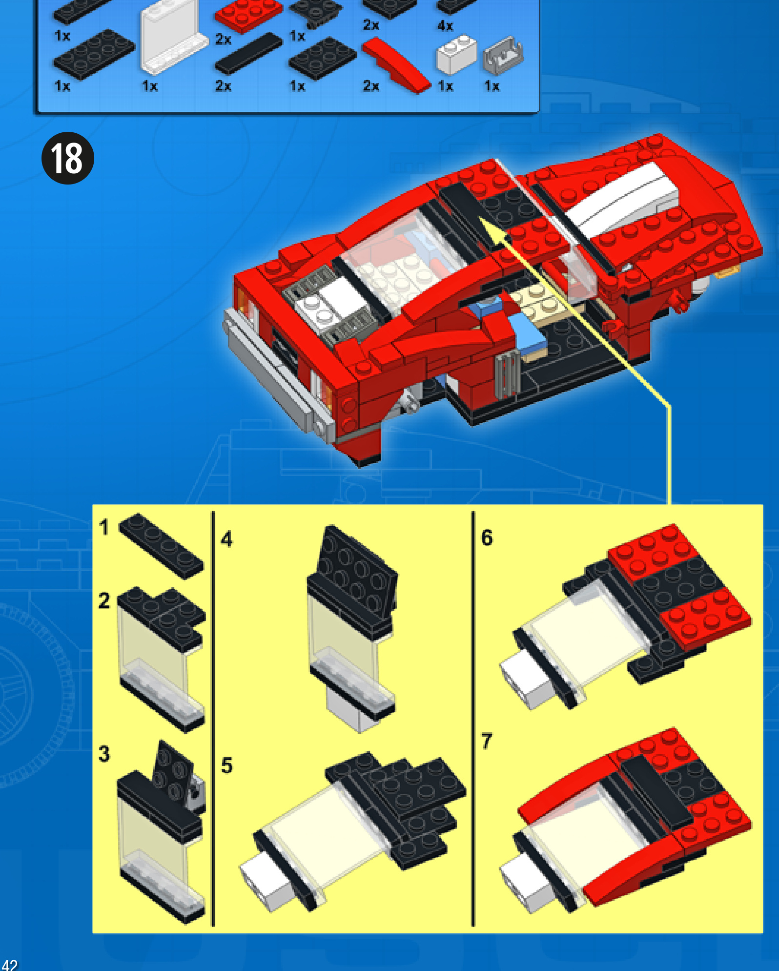
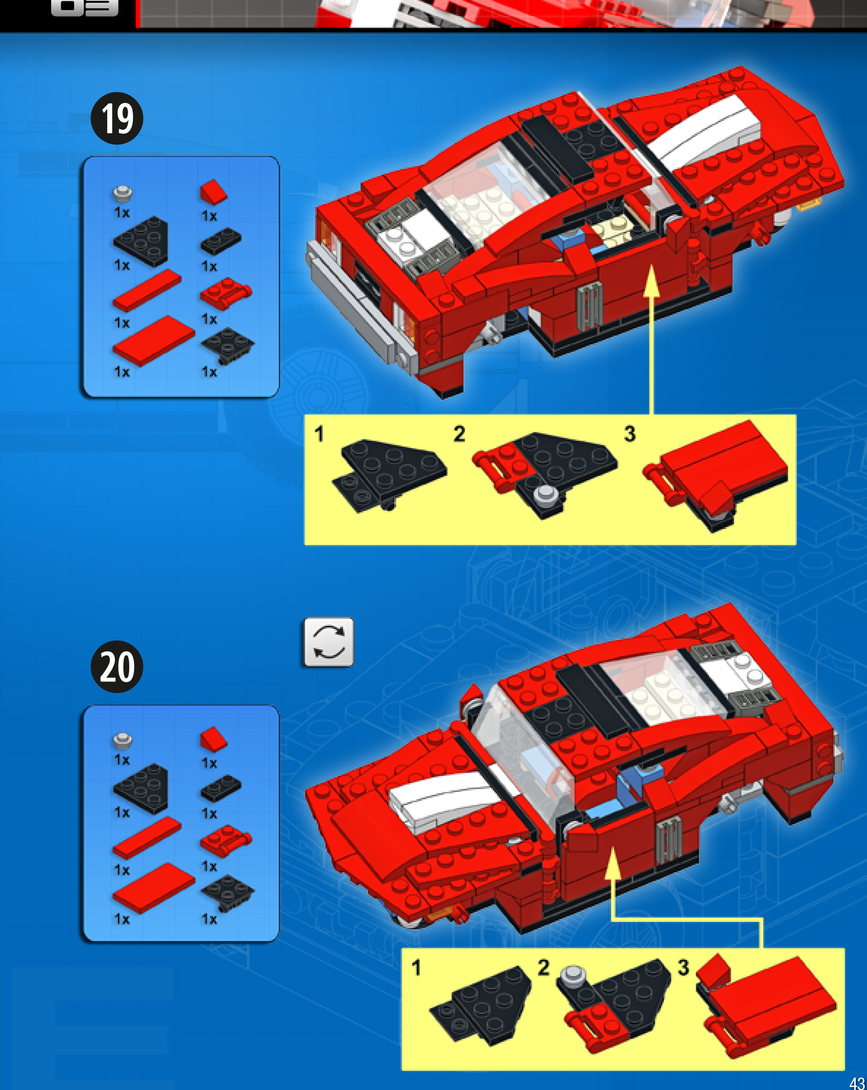
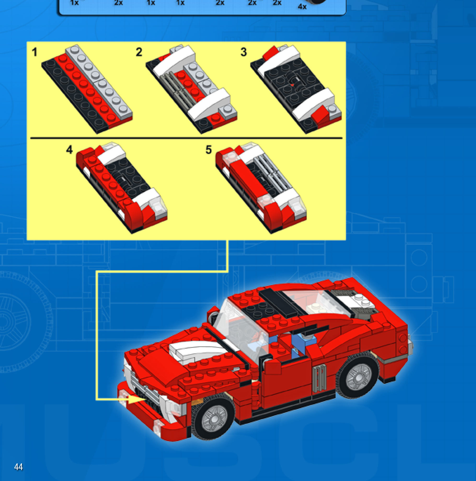
STROLLER
Design notes: open frame, upright chair, curvedhandlebars
Technical specifications: Dimensions (I xw× h): Wheelbase: Axle width front/rear:
14× 10 × 15 studs
8 studs
10/10 studs
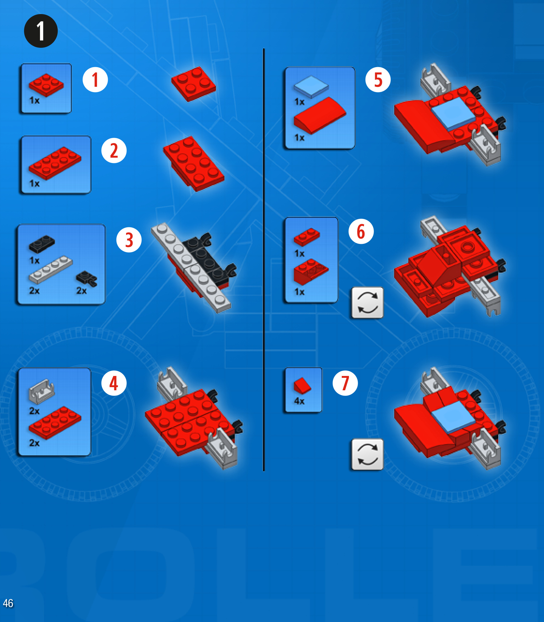
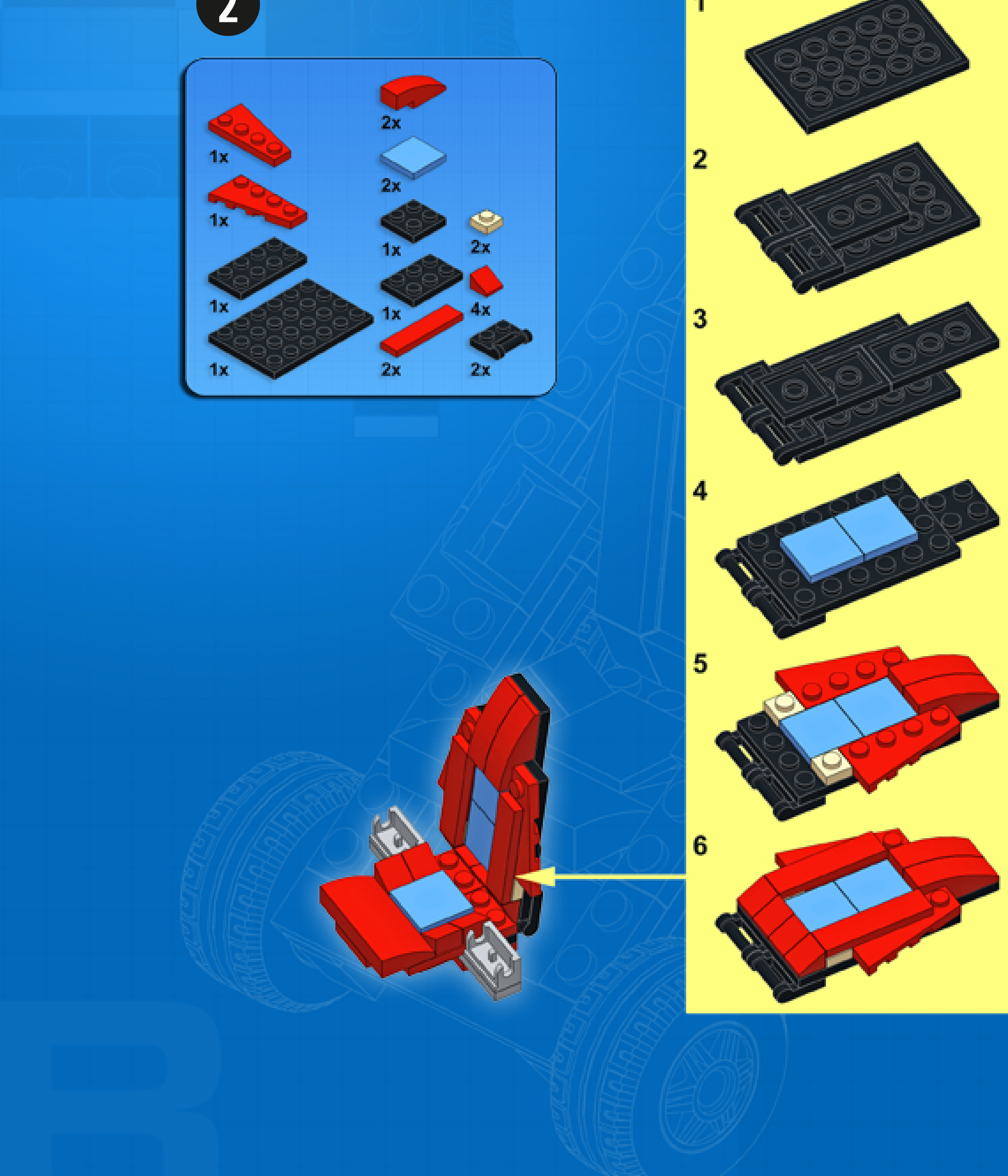
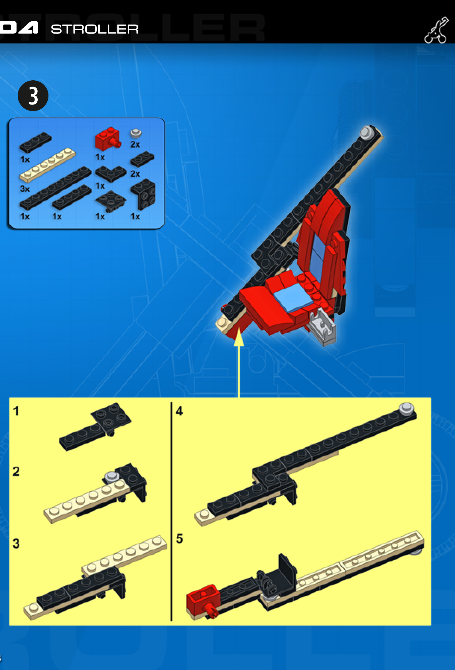
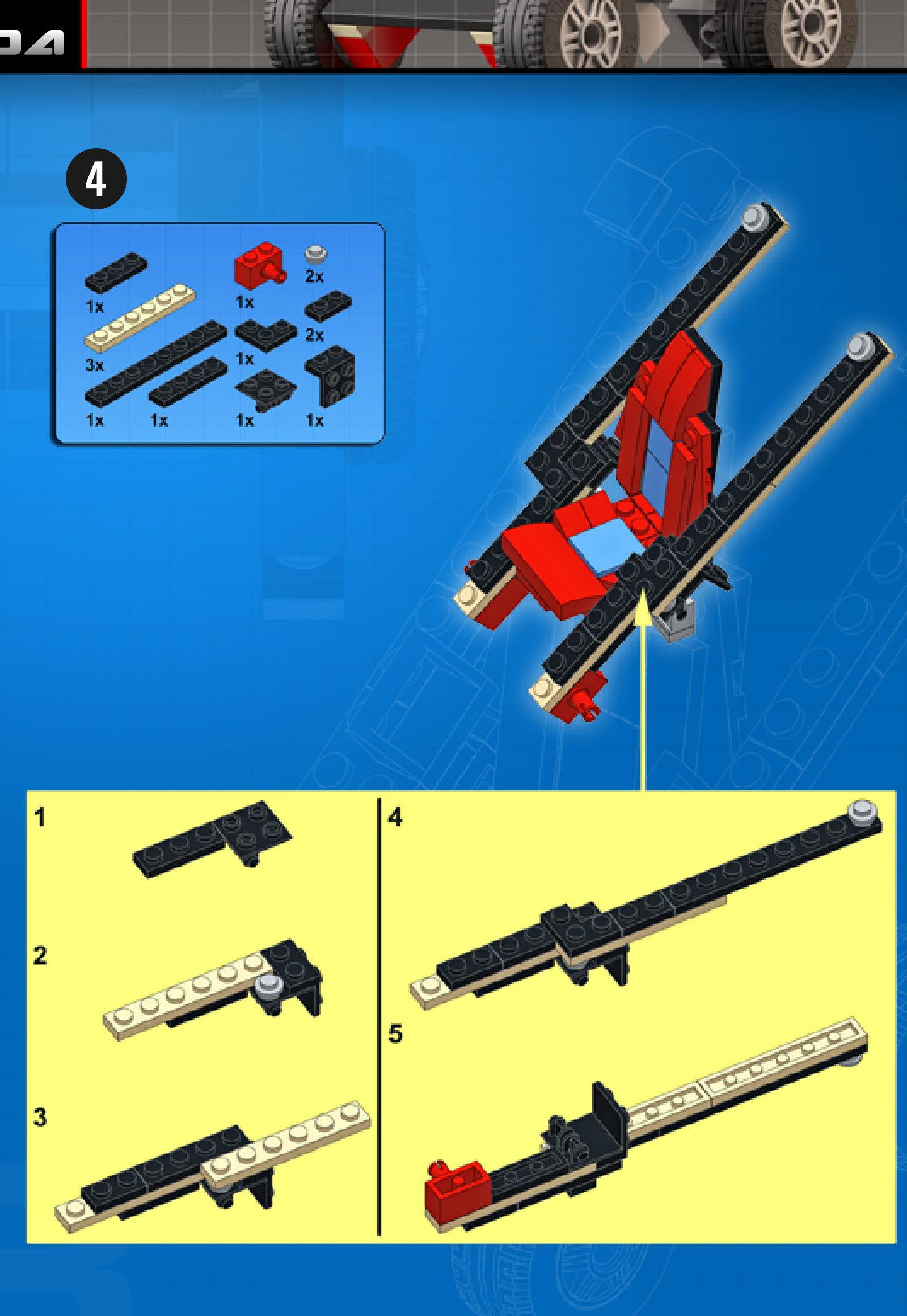
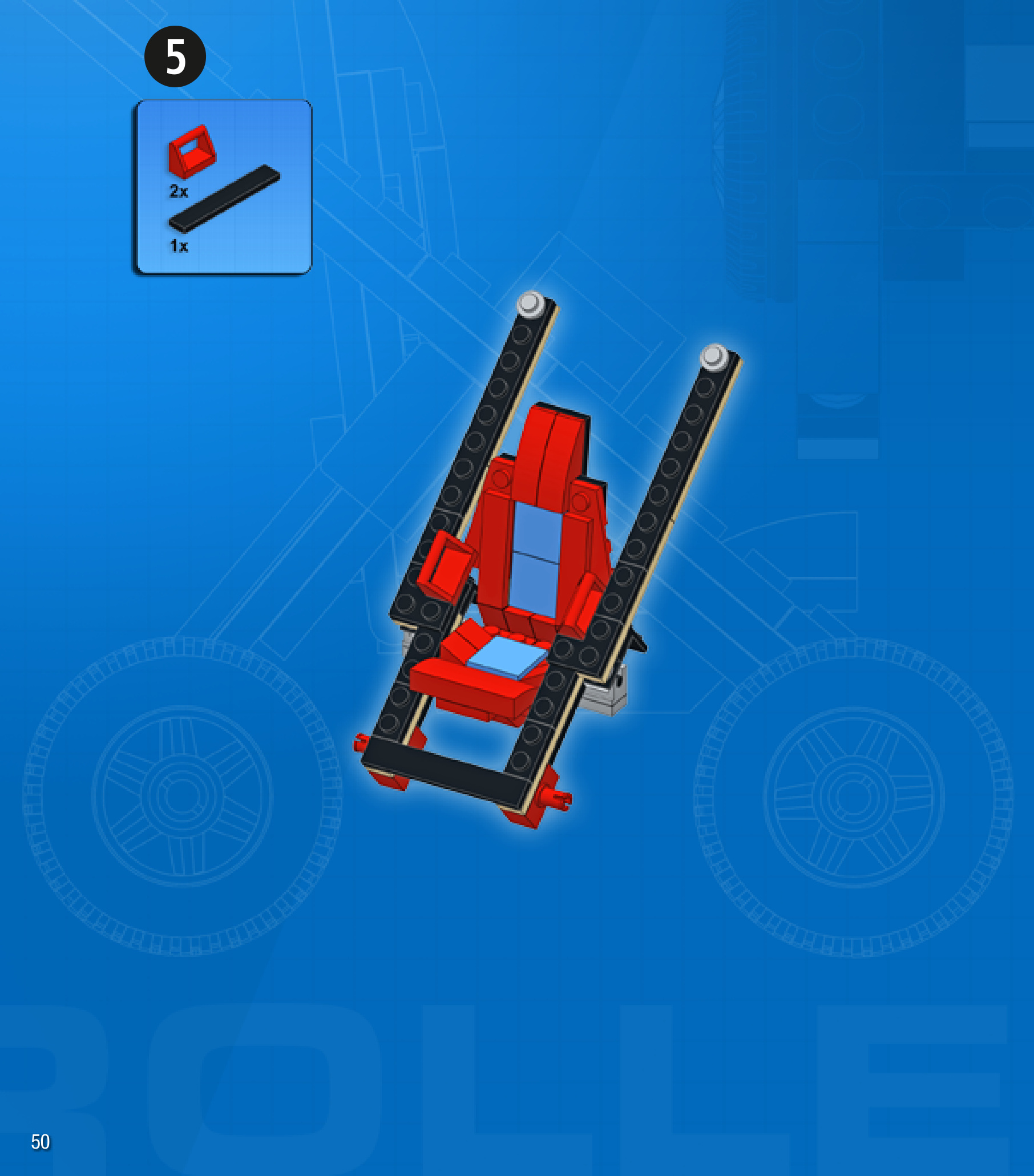
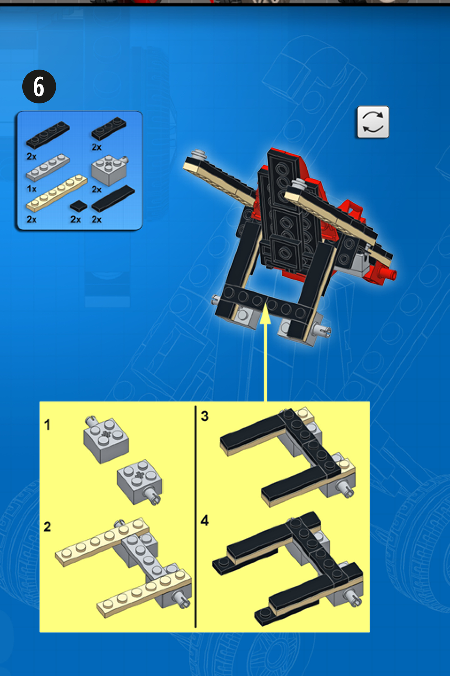
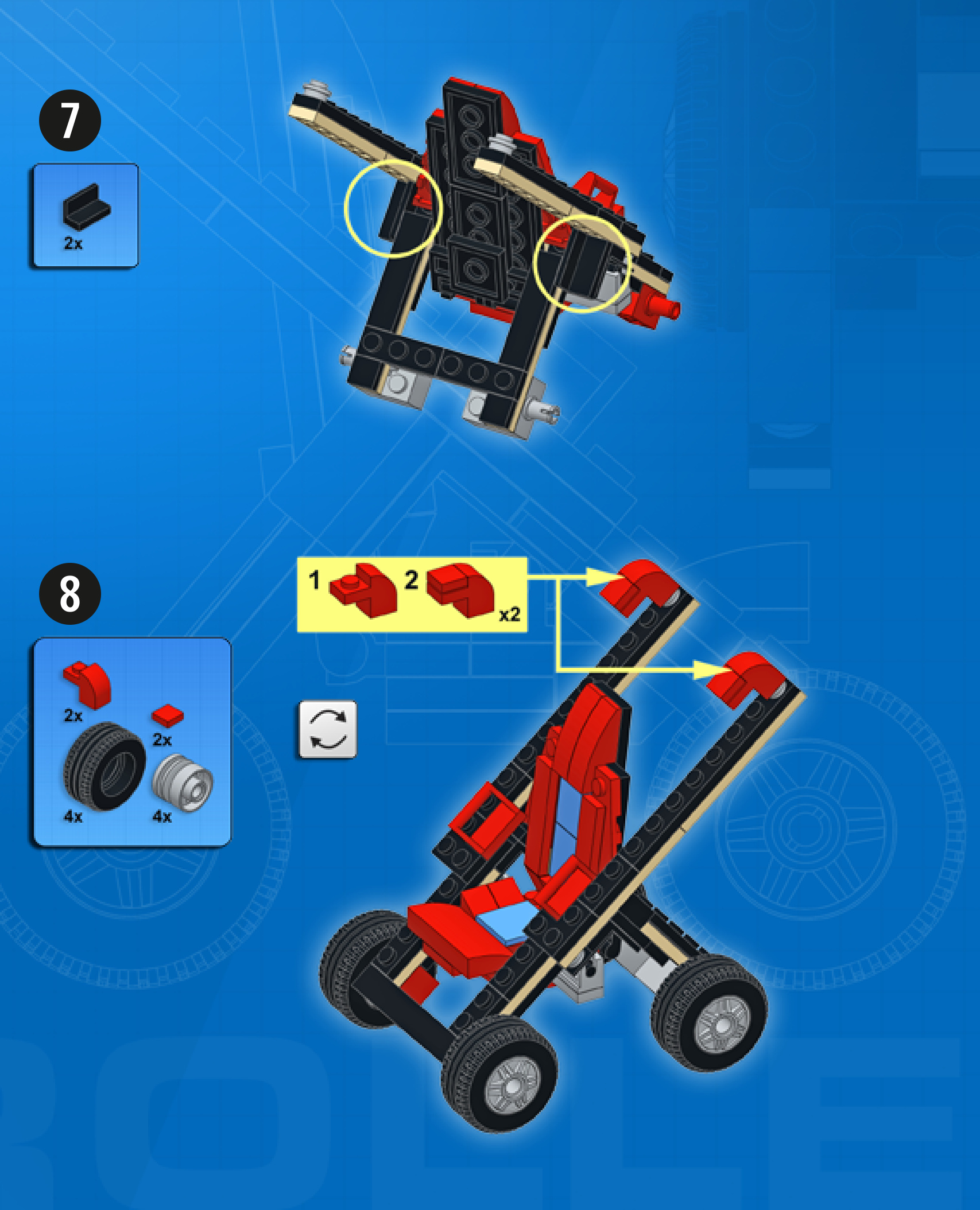
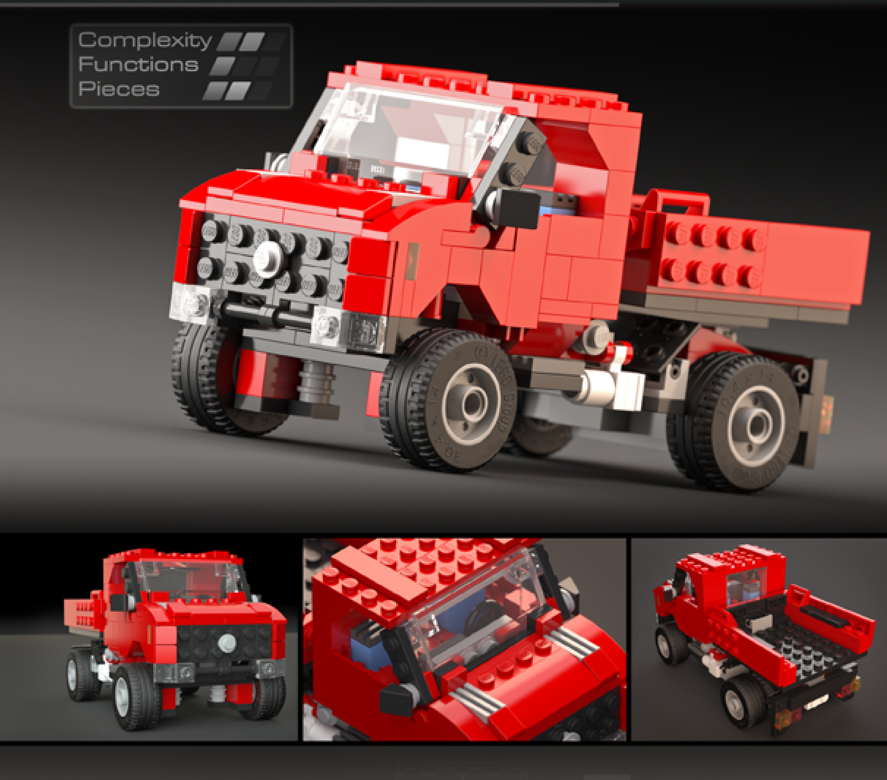
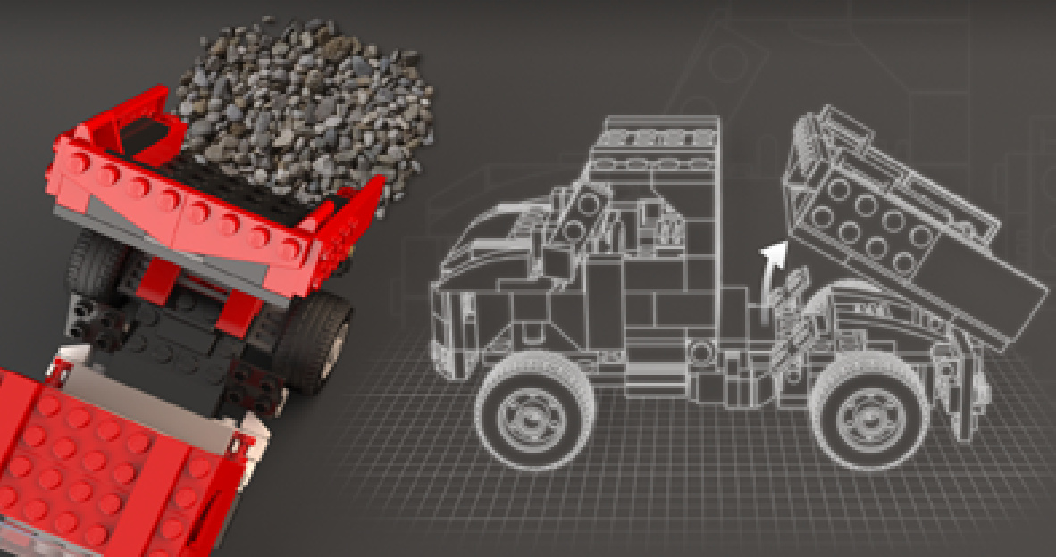
MULTI-PURPOSETRUCK
Design notes: short nose, wide axle, high clearance
Technical specifications: Dimensions (l xw × h): 19 × 11 × 11 studs Wheelbase: 11 studs Axlewidthfront/rear: 10/10 studs
Features: tipping bed
1


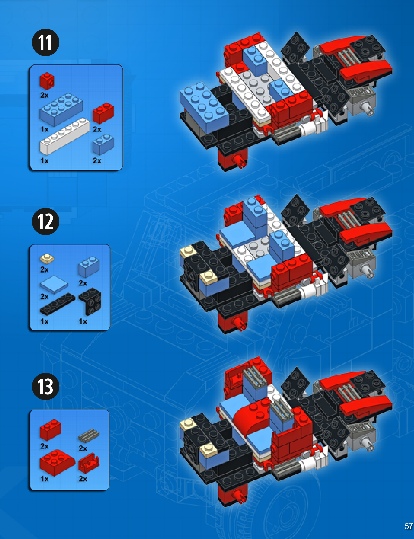
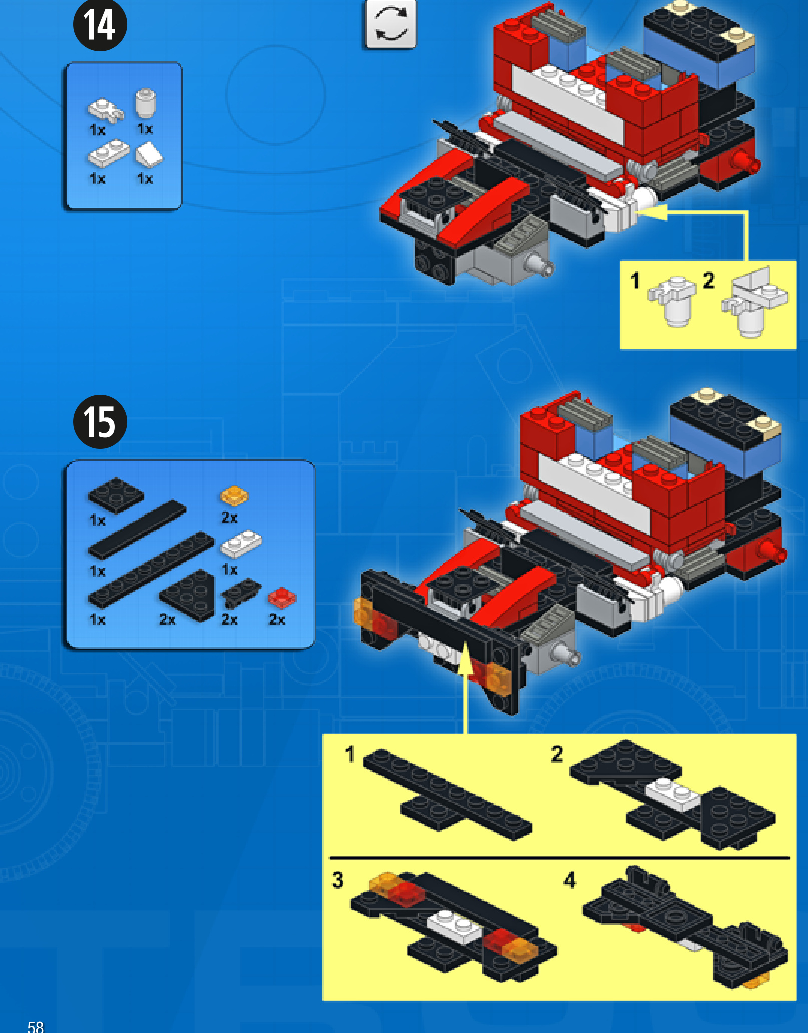

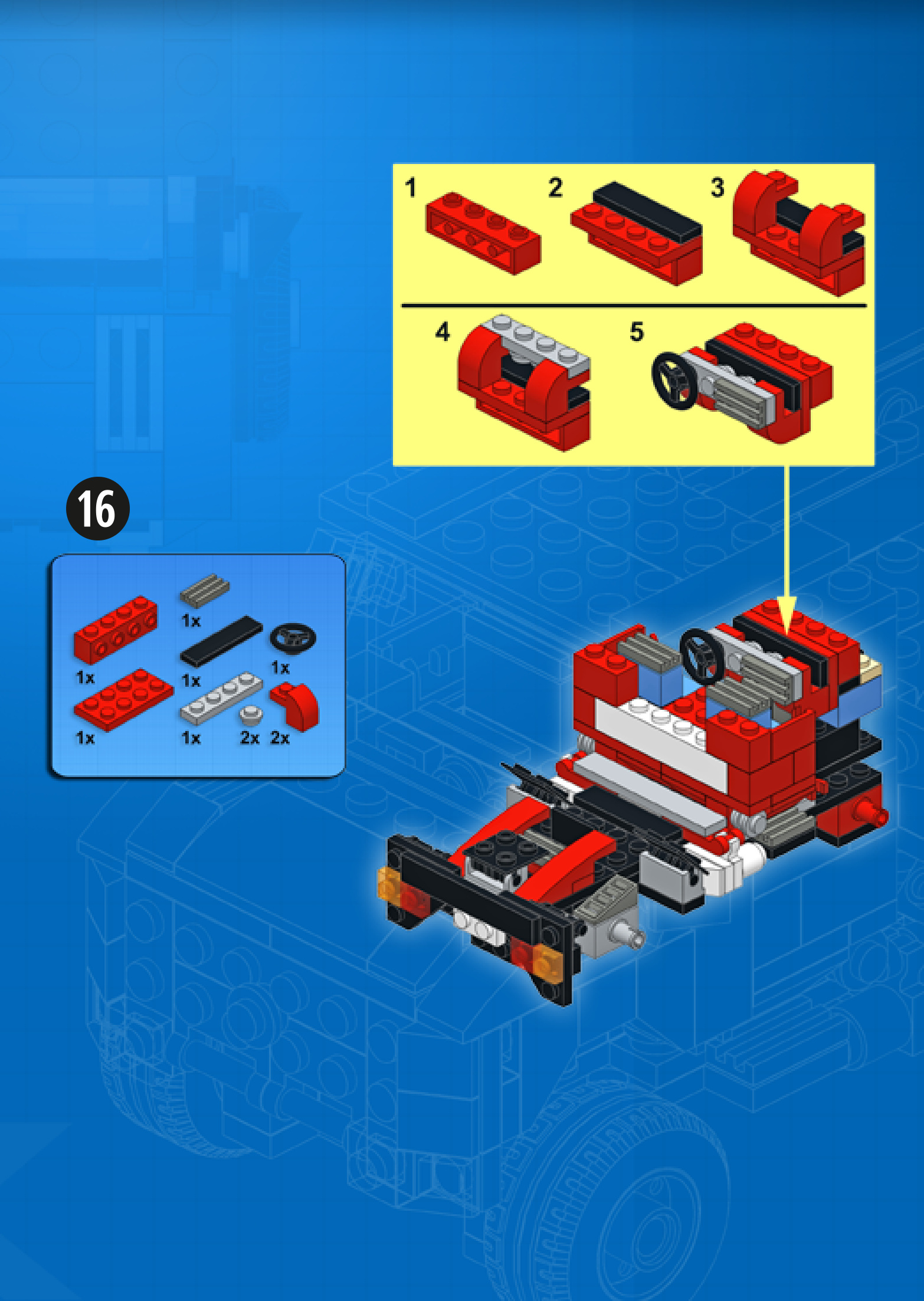
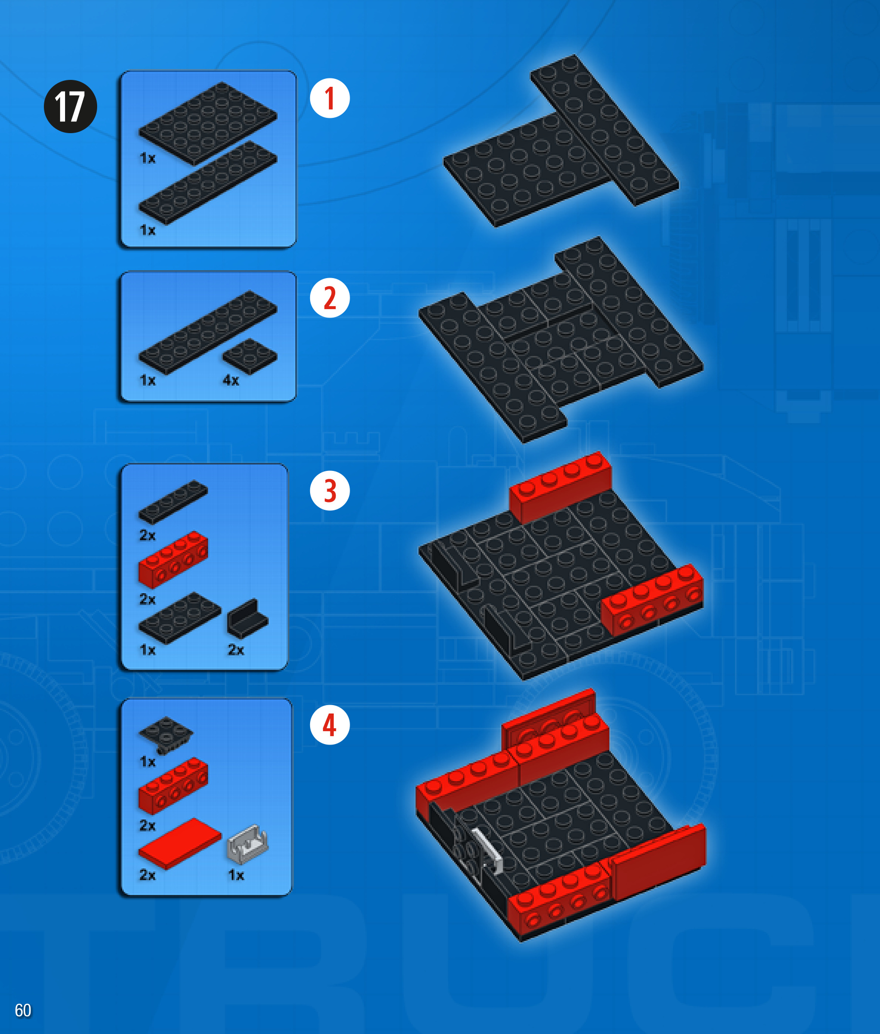

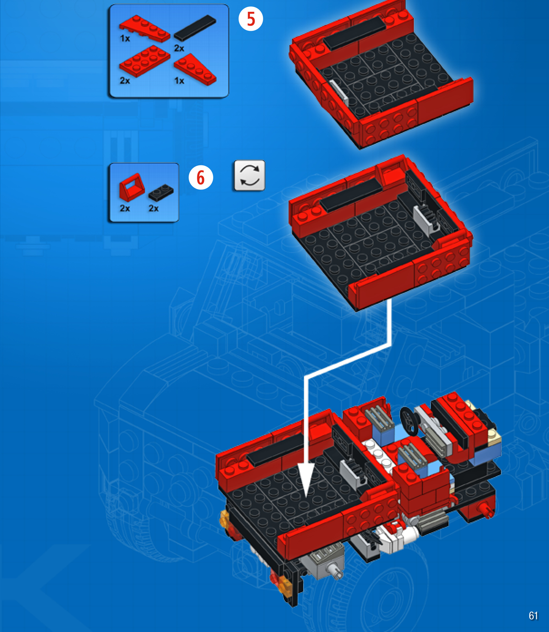
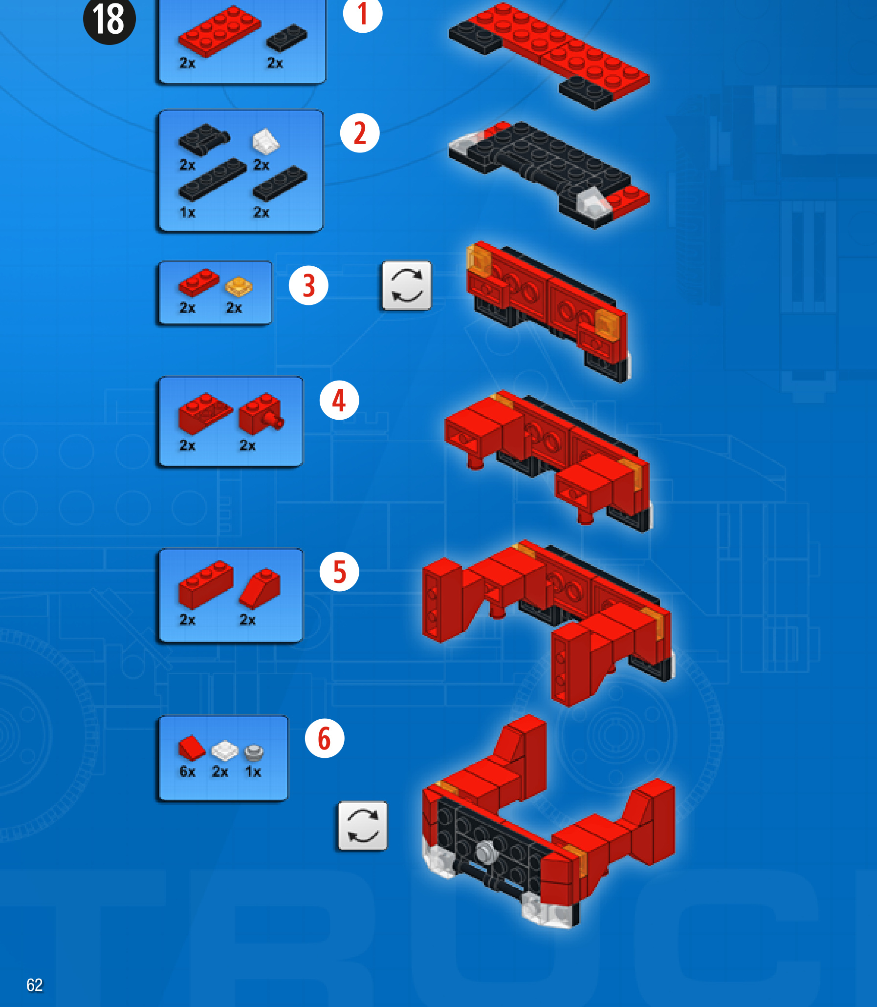

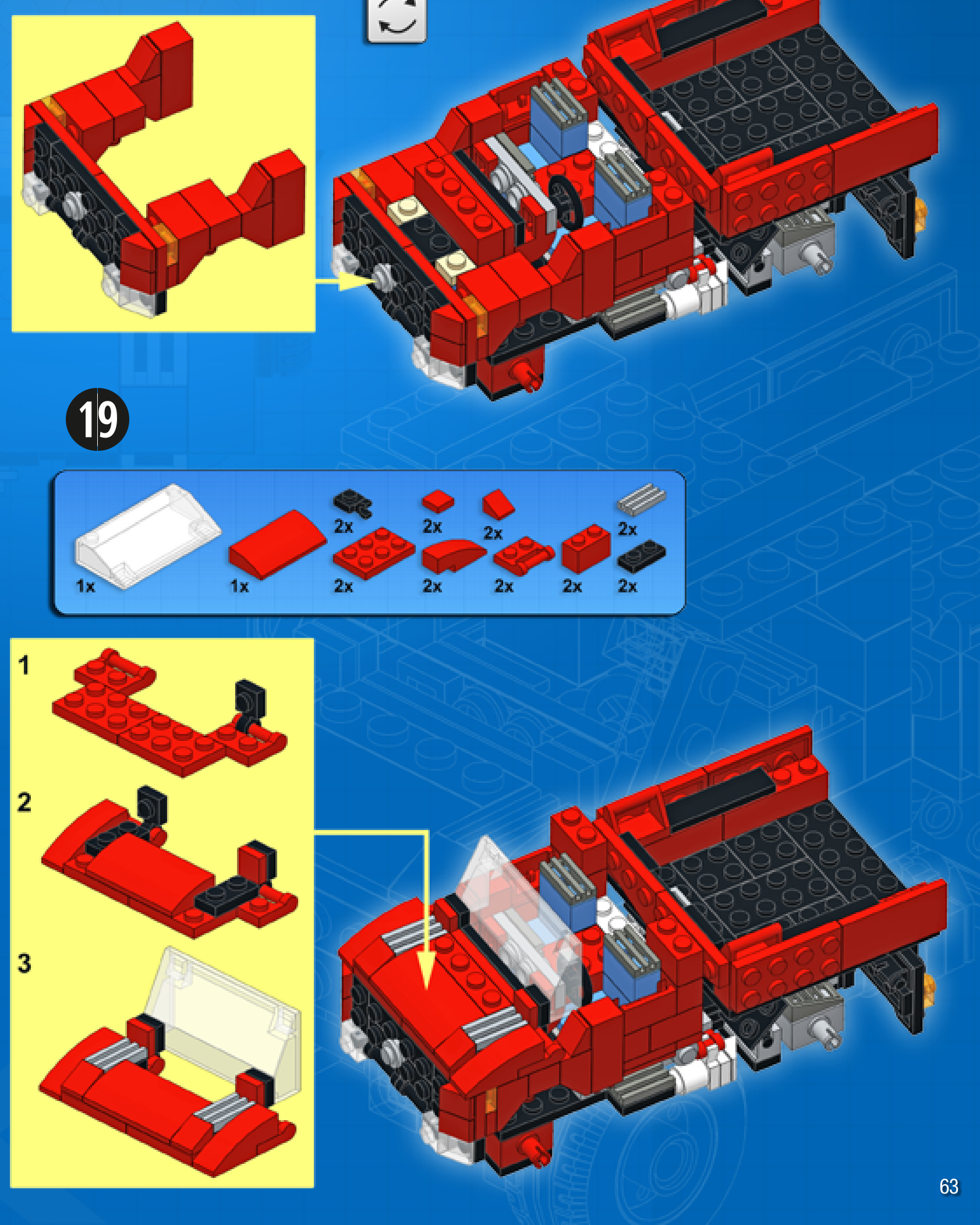
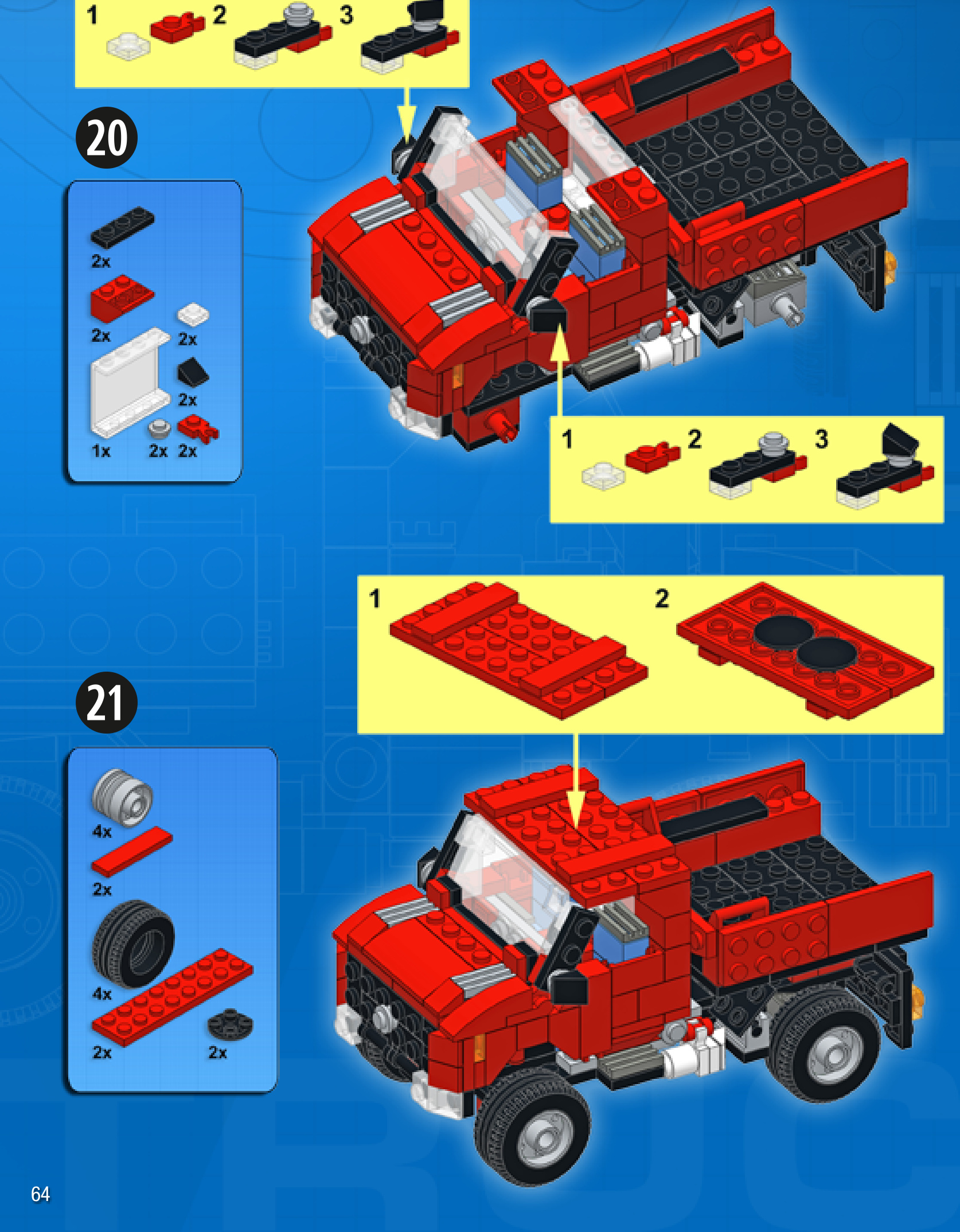


NOW YOU’RE READY TO LEARN SOME ADVANCED BUILDING TECHNIQUES!
HERE ARE A FEW IDEAS FOR CREATING STURDY CROSS-CONNECTIONS BETWEEN PIECES.
THAT’S A STRONG CONNECTION!
WHAT HAPPENS WHEN YOU BUILD SIDEWAYS AFTER YOU’VE ALREADY GONE SIDEWAYS?WELL, THEN YOU’RE BUILDING UPSIDE DOWN!
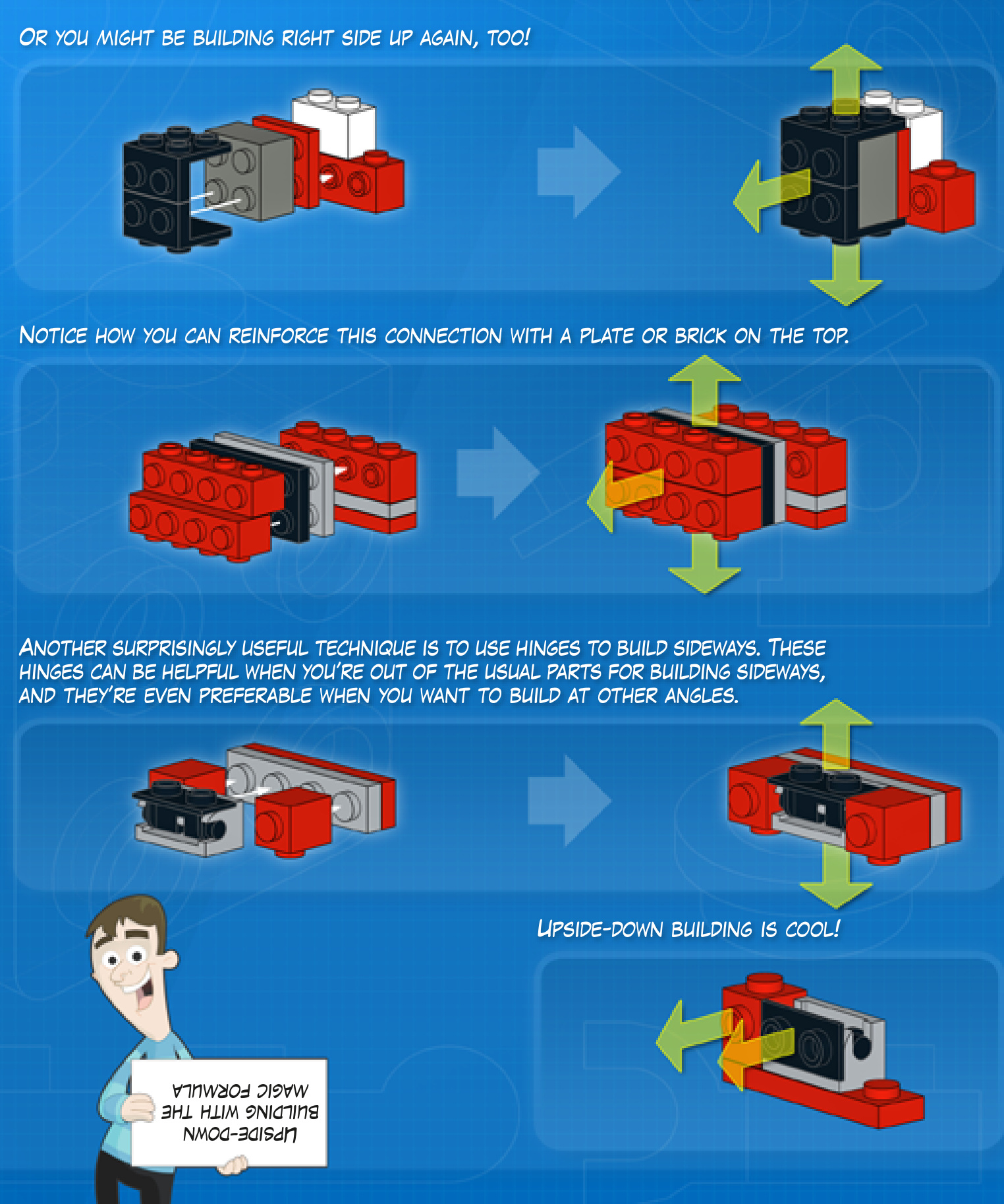
HINGES AND PINS ARE VERY USEFUL FOR CREATING FLEXIBLE JOINTS AND ARTICULATION.
DIFFERENT HINGES HAVE DIFFERENT LIMITATIONS, THOUGH.
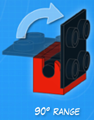
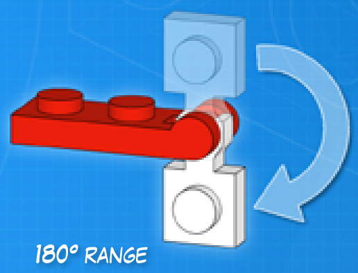
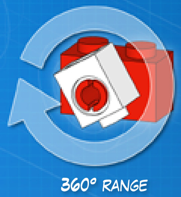
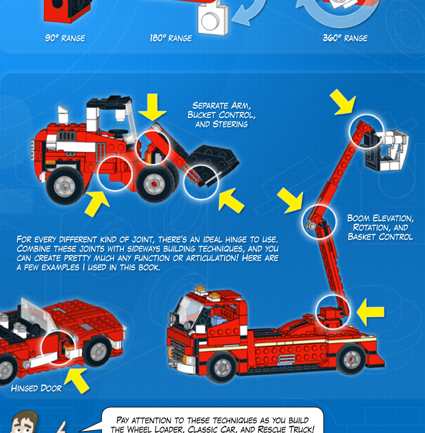

Complexity Functions Pieces
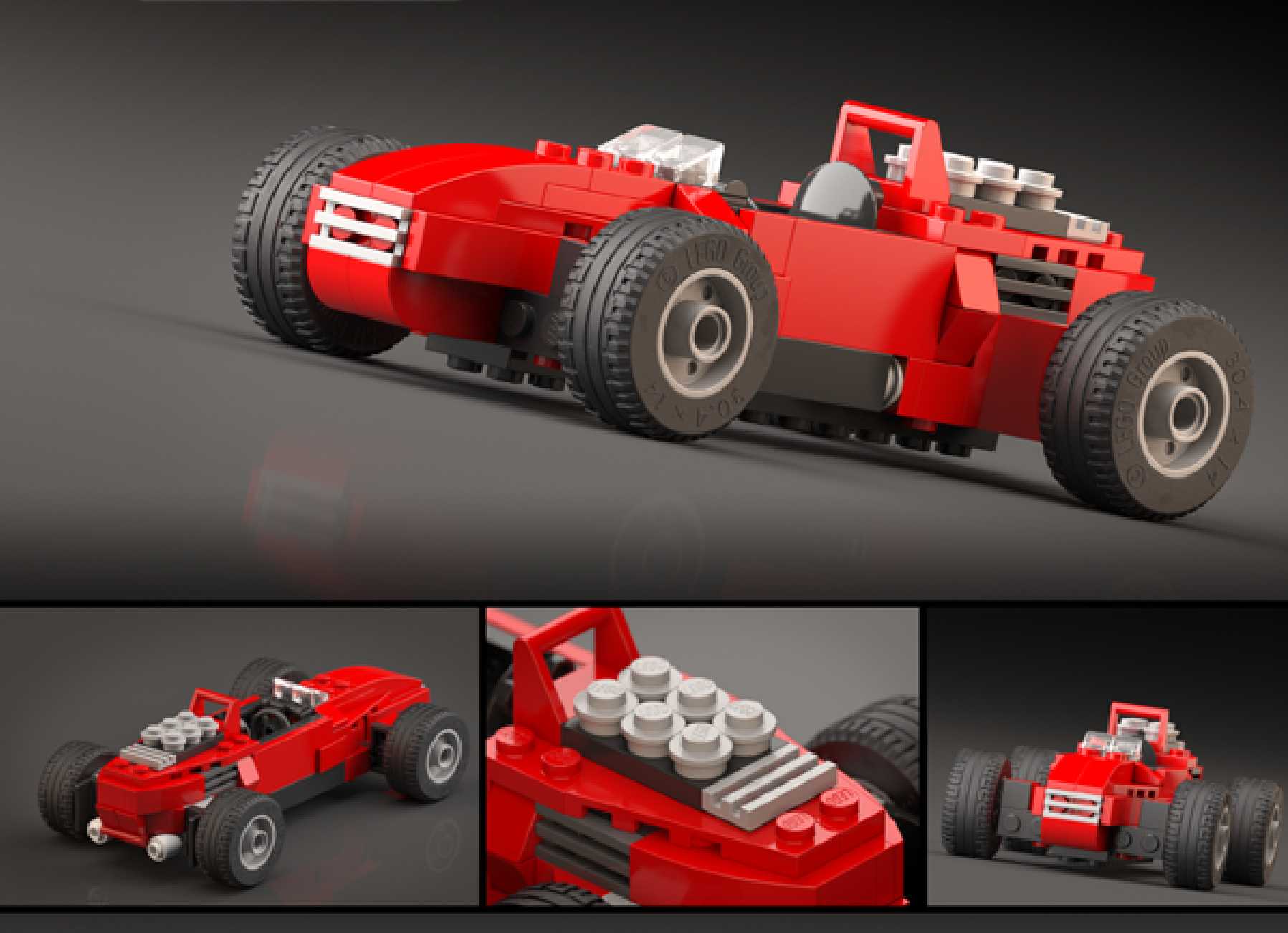
HISTORIC RACER
Design notes: bullet shape, minimal aeroscreen,wide wheelbase,sixcylinder engine, rollbar
Technical specifications: Dimensions (lxwx h): 19×10×6 studs Wheelbase: 12 studs Axle width front/rear: 10/10 studs

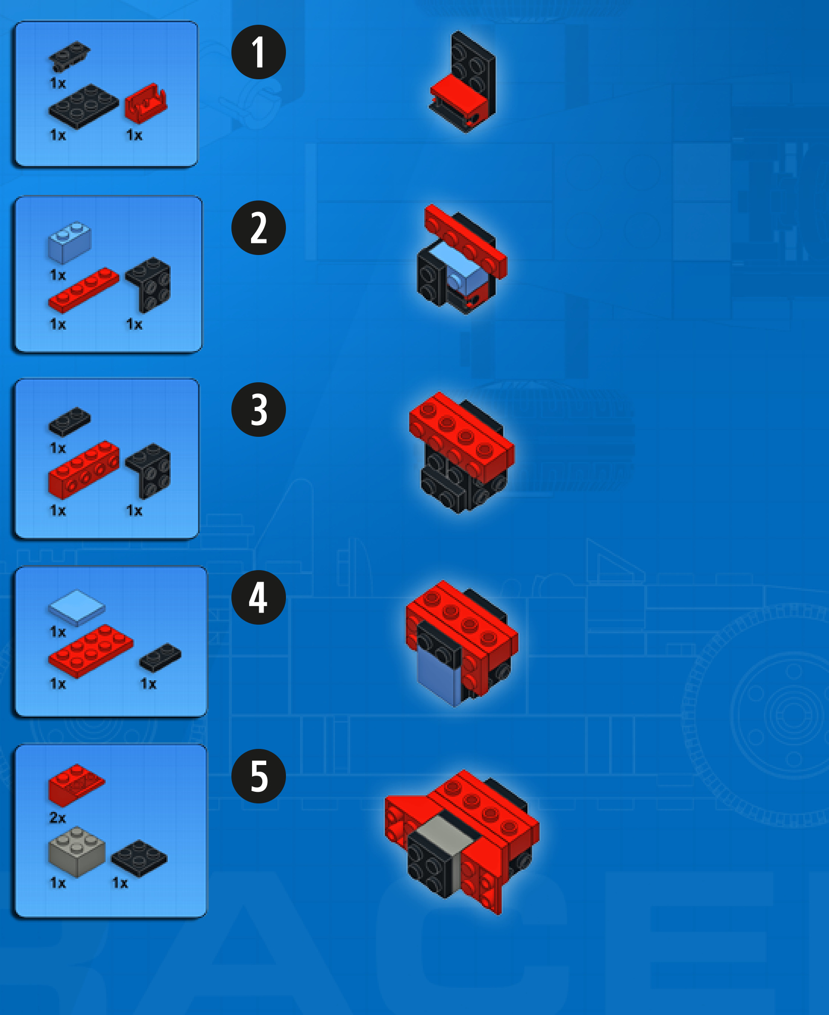
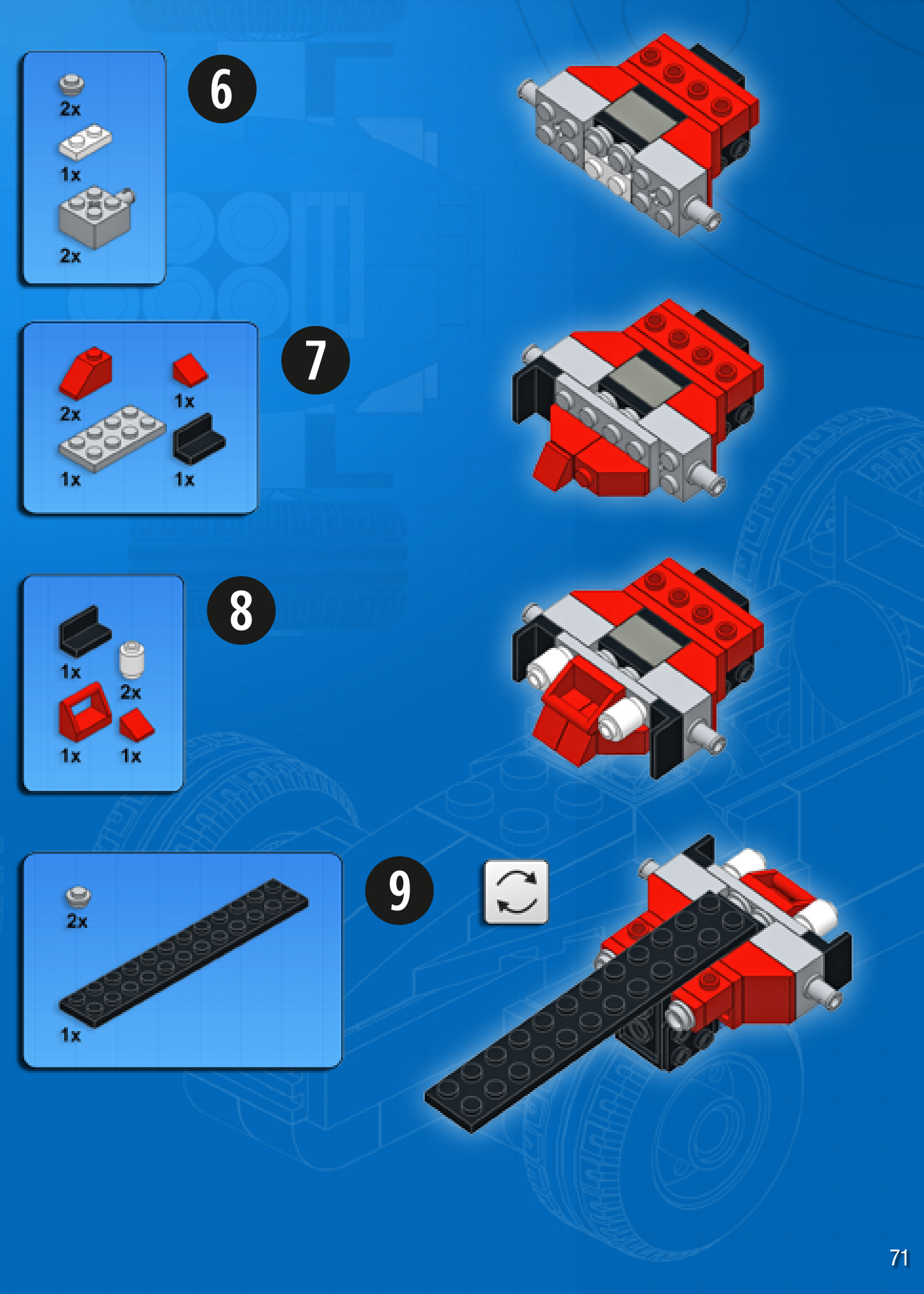
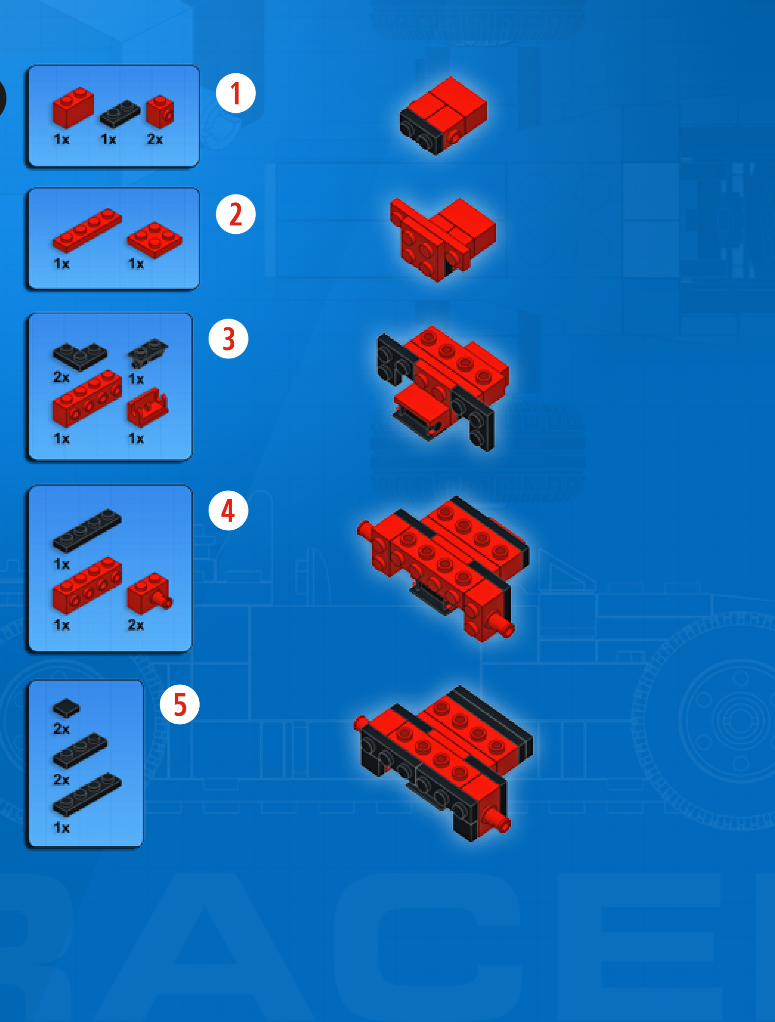
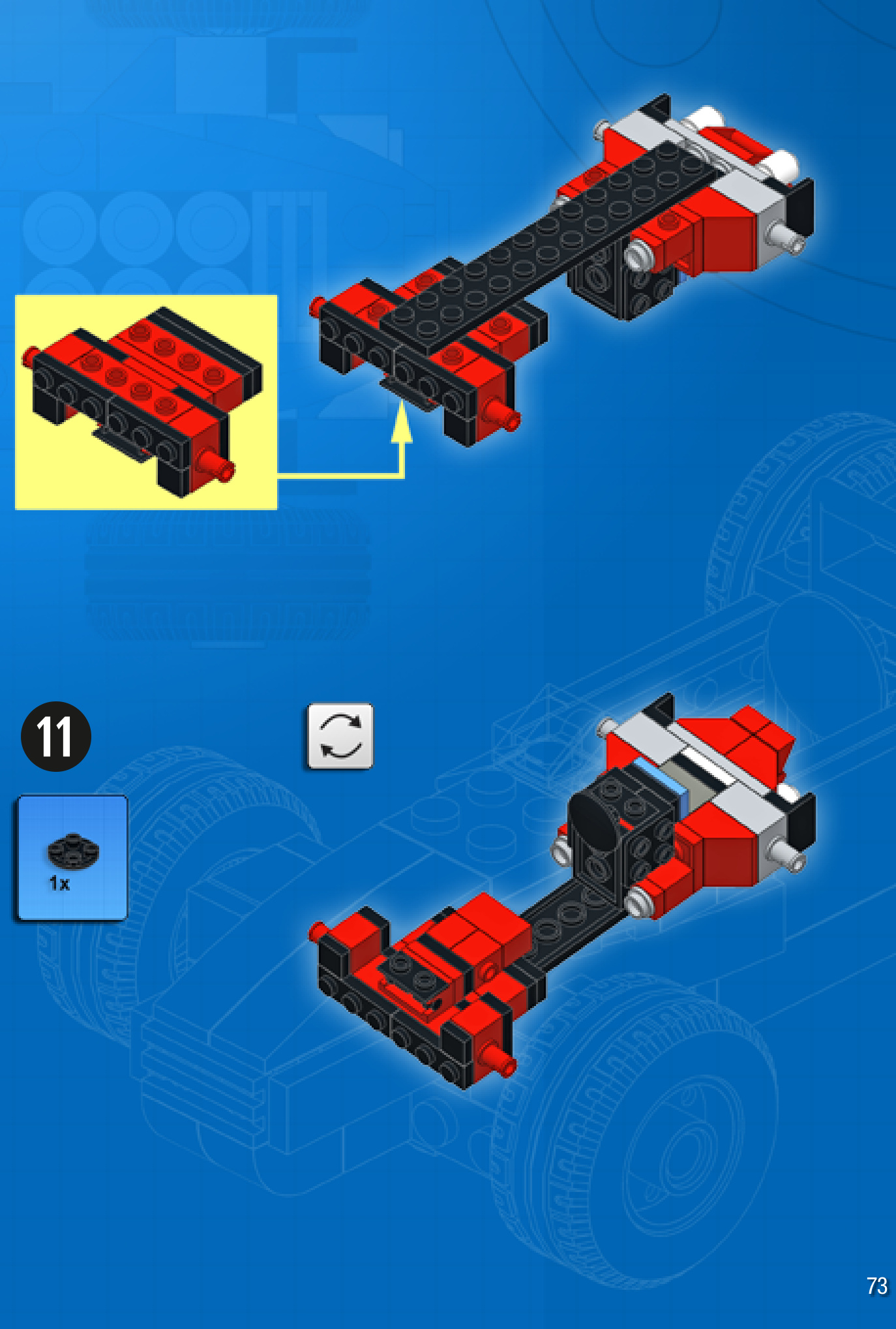
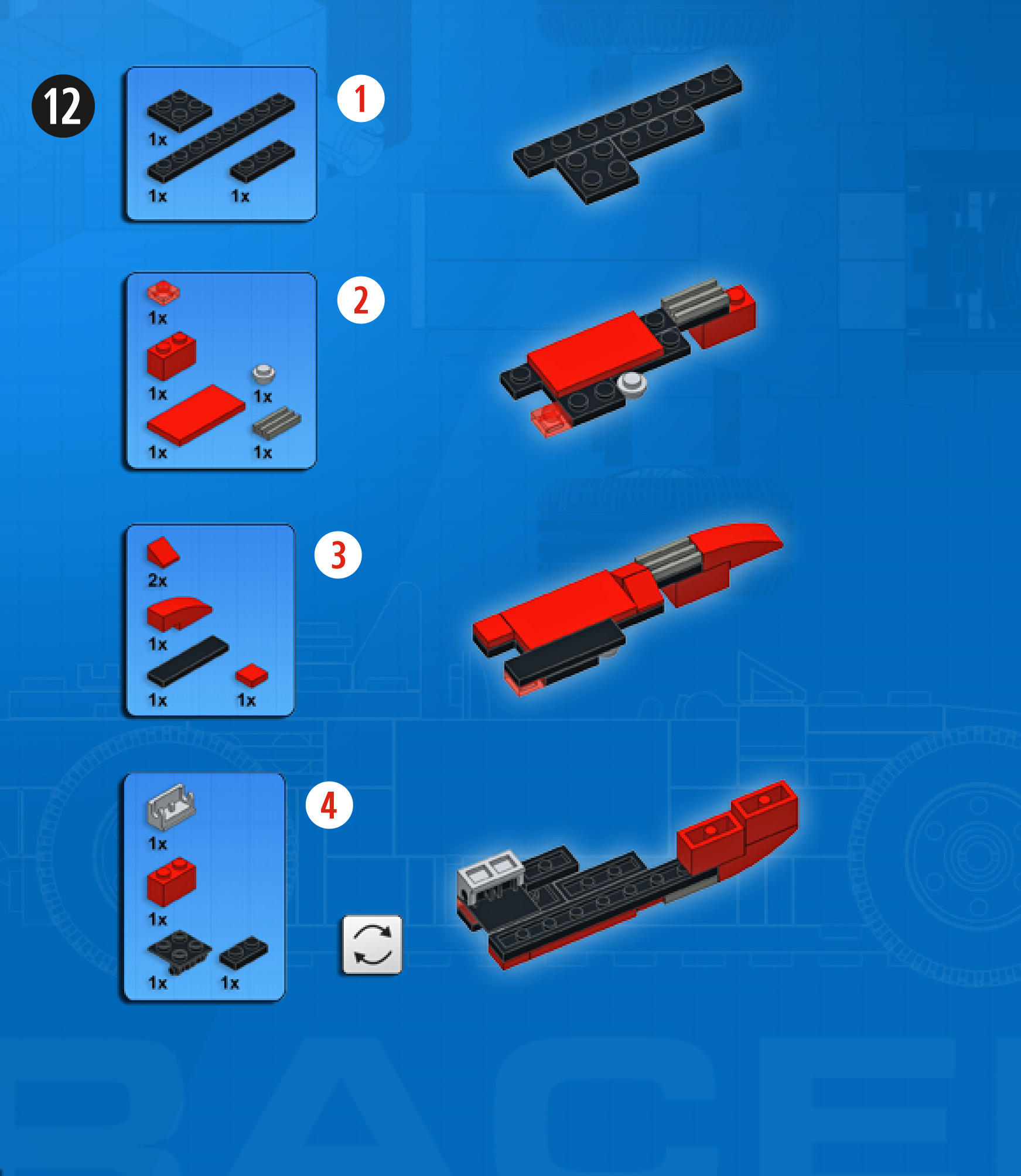
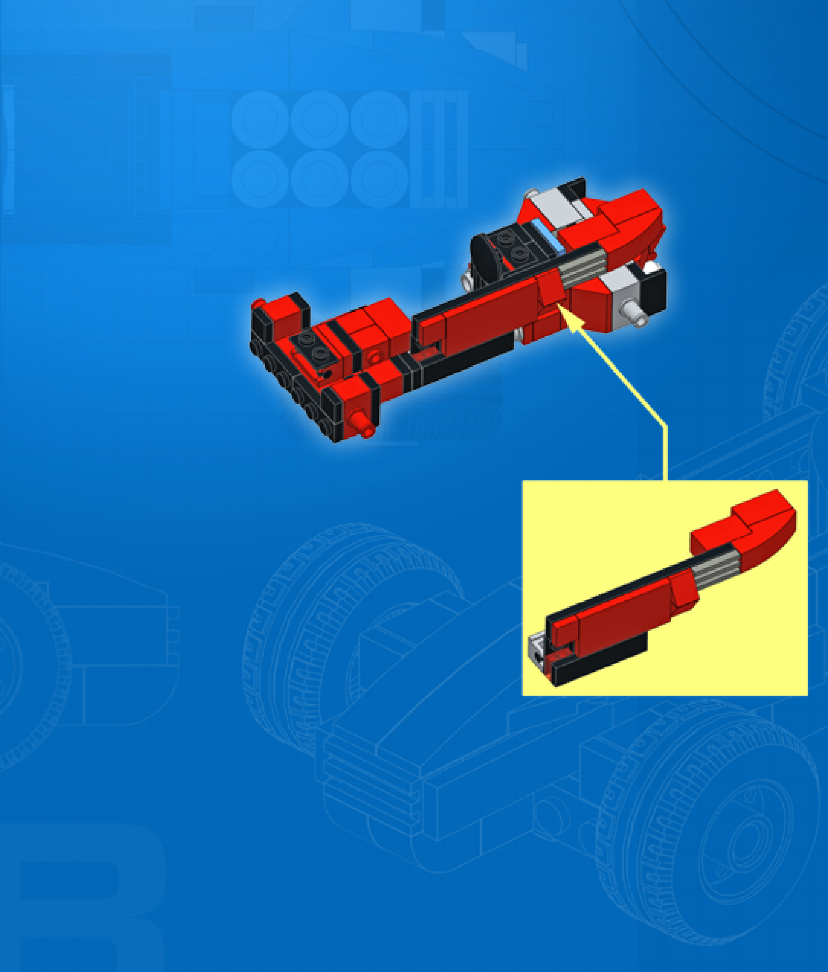
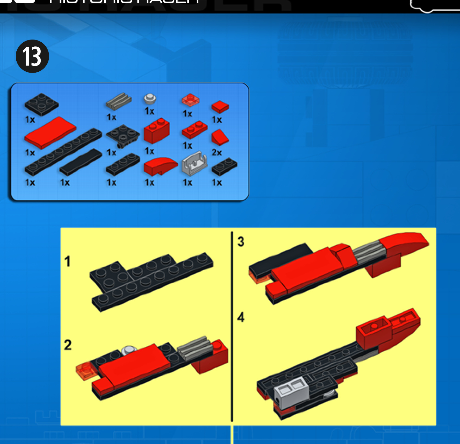
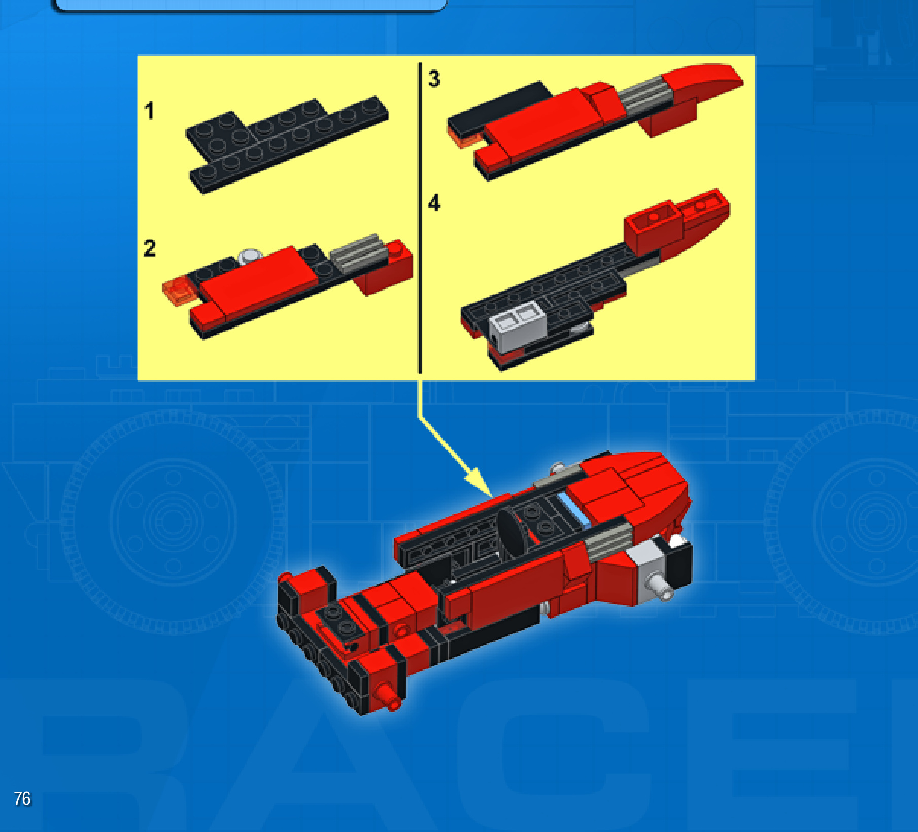
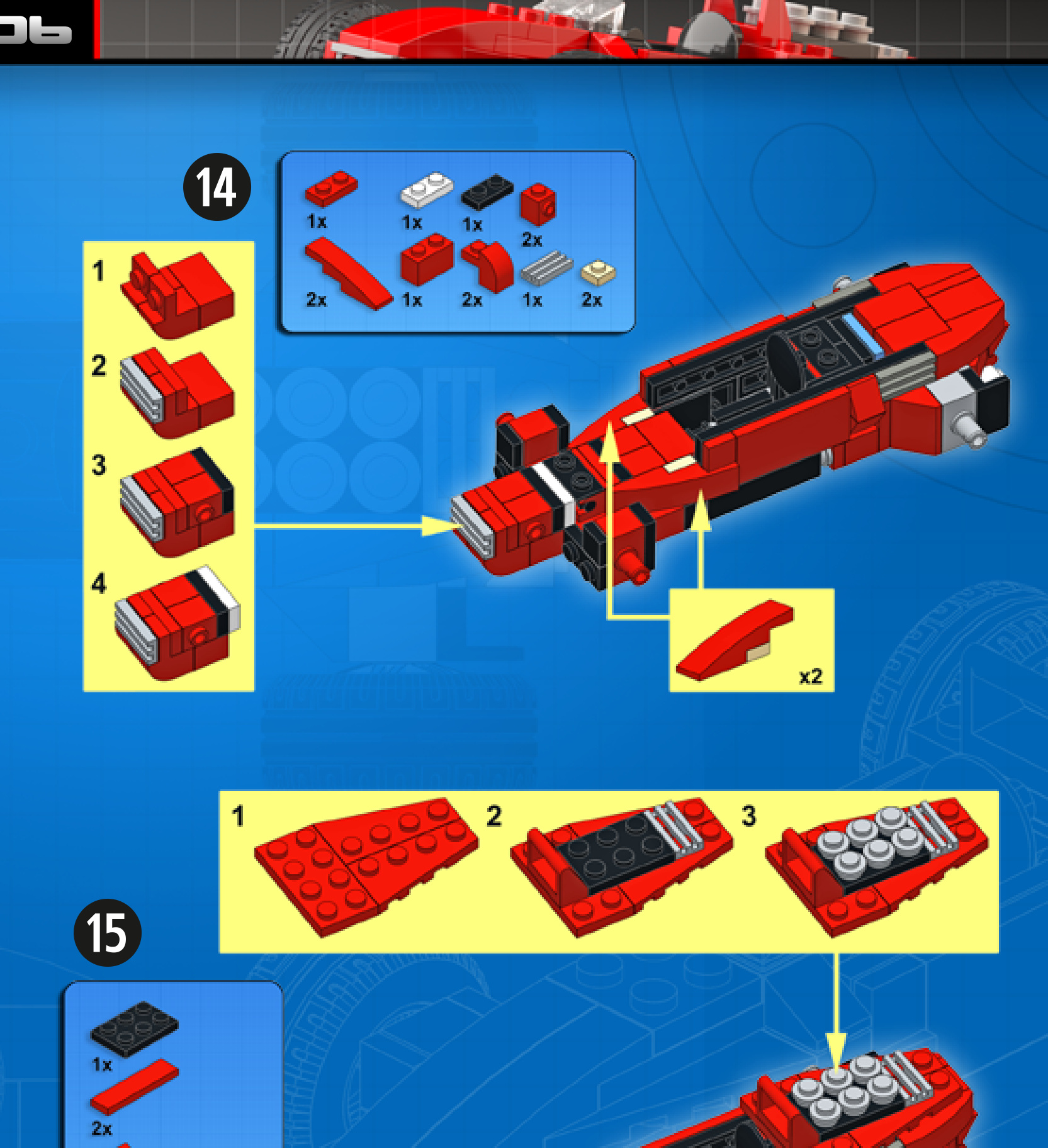
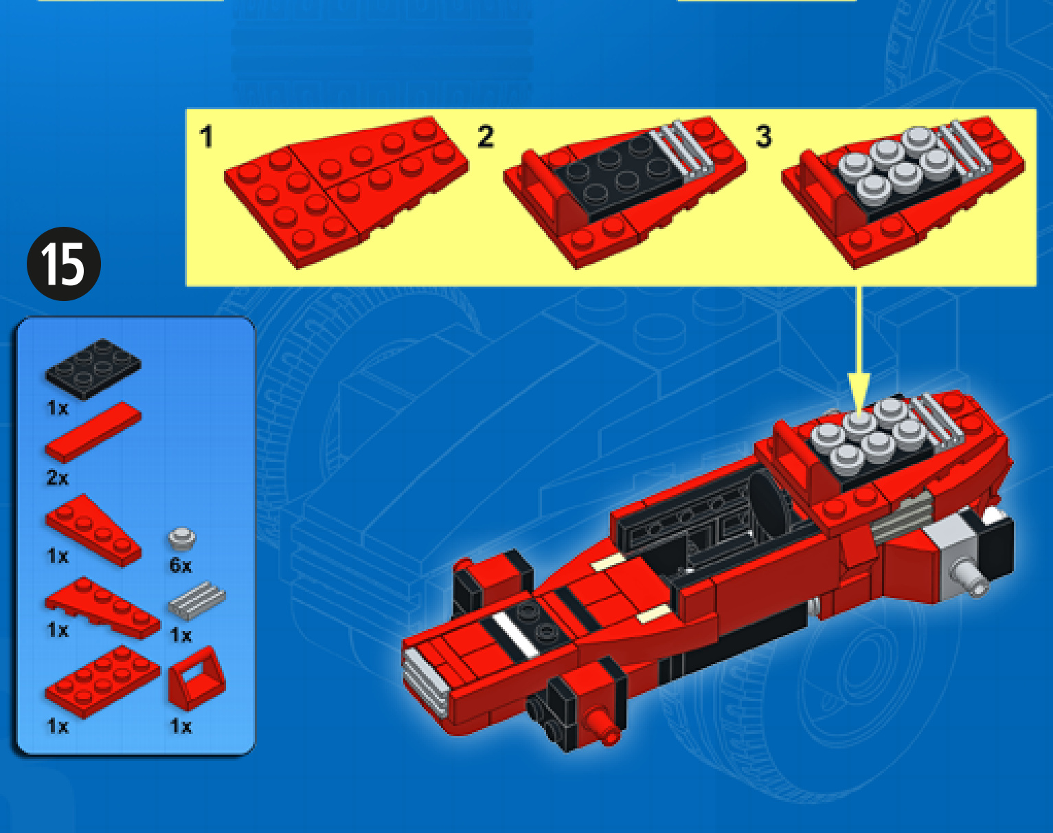
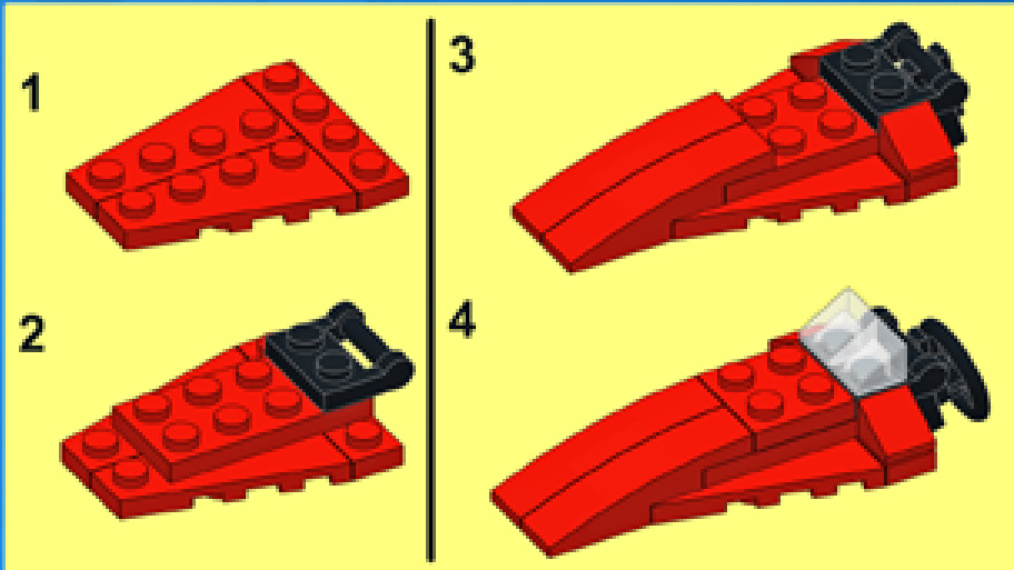
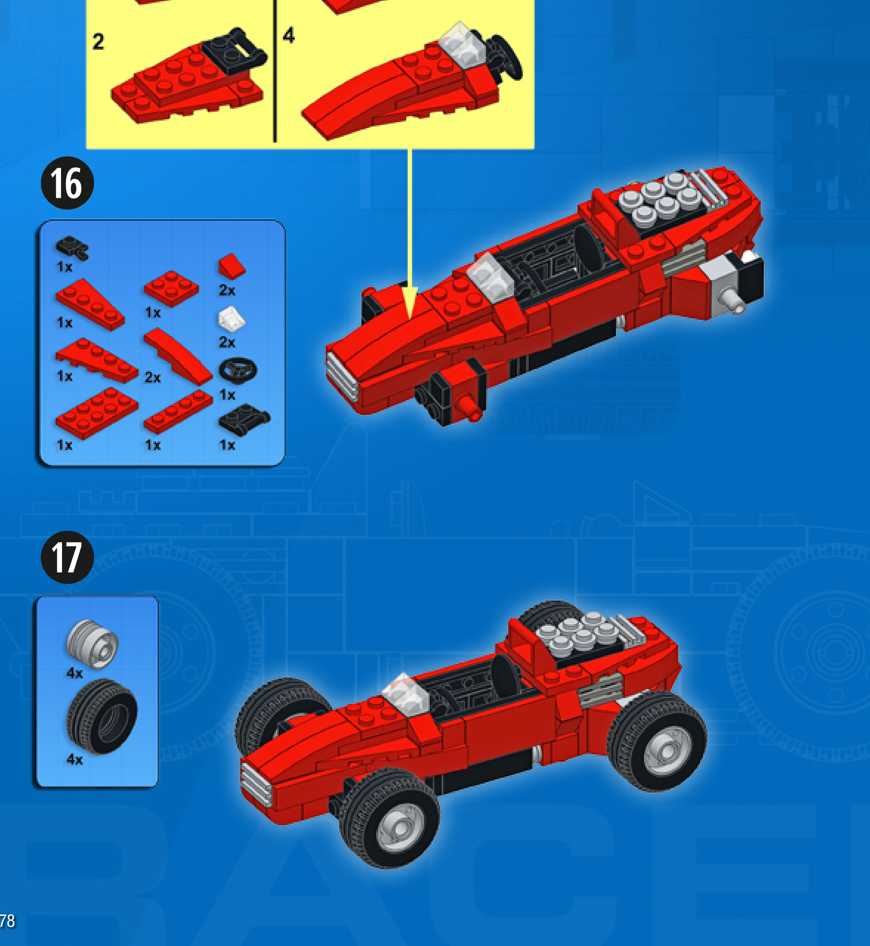
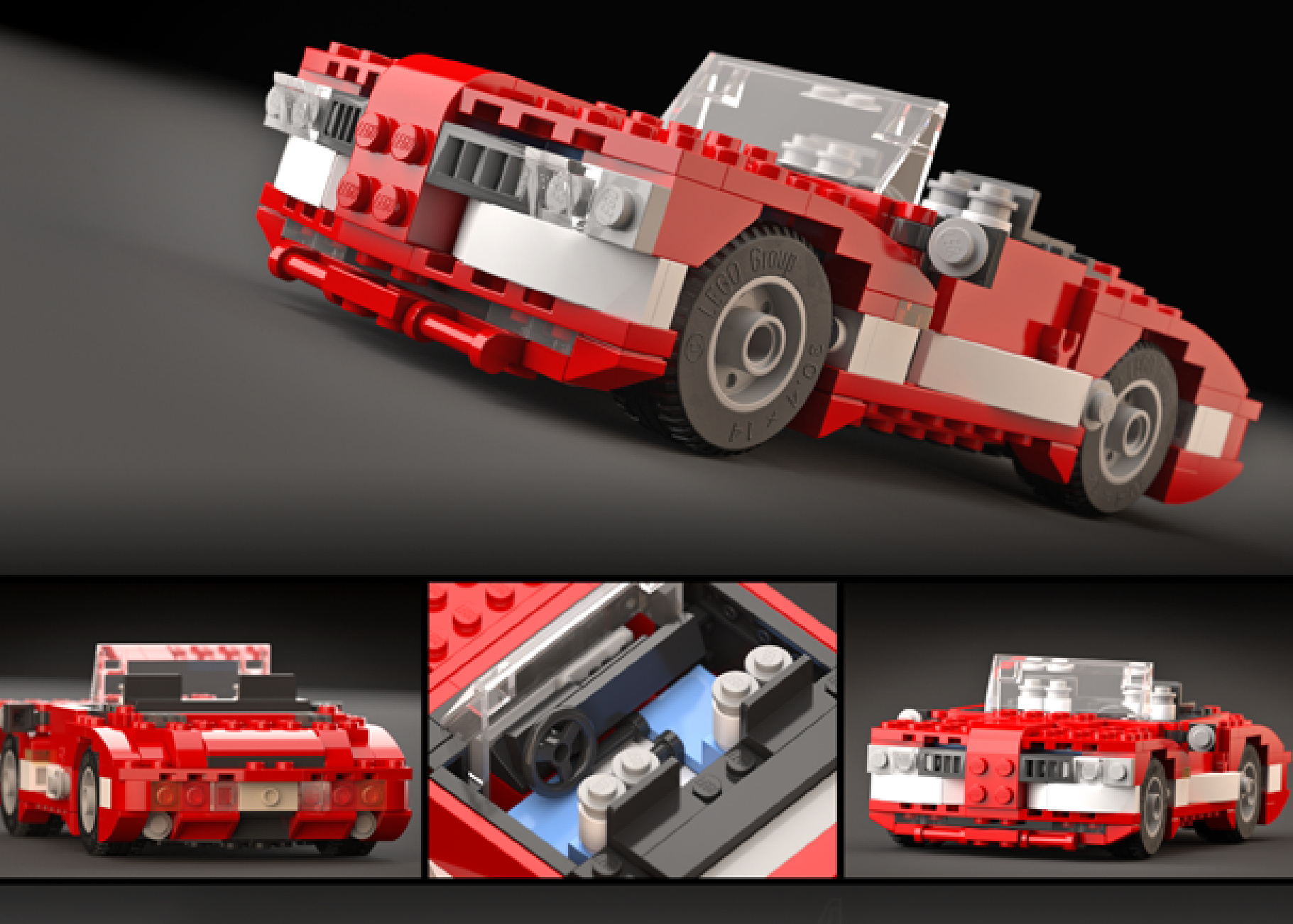
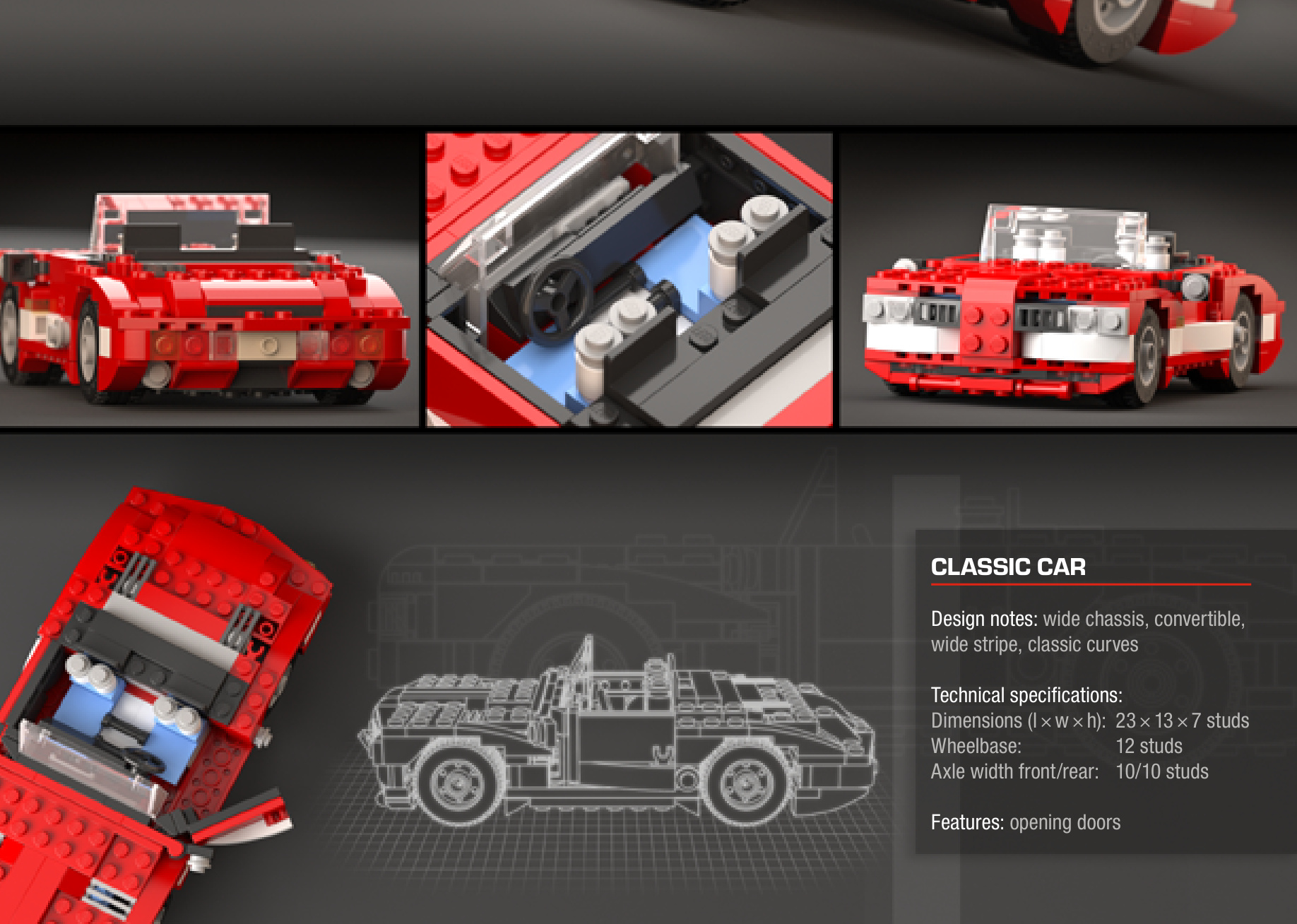
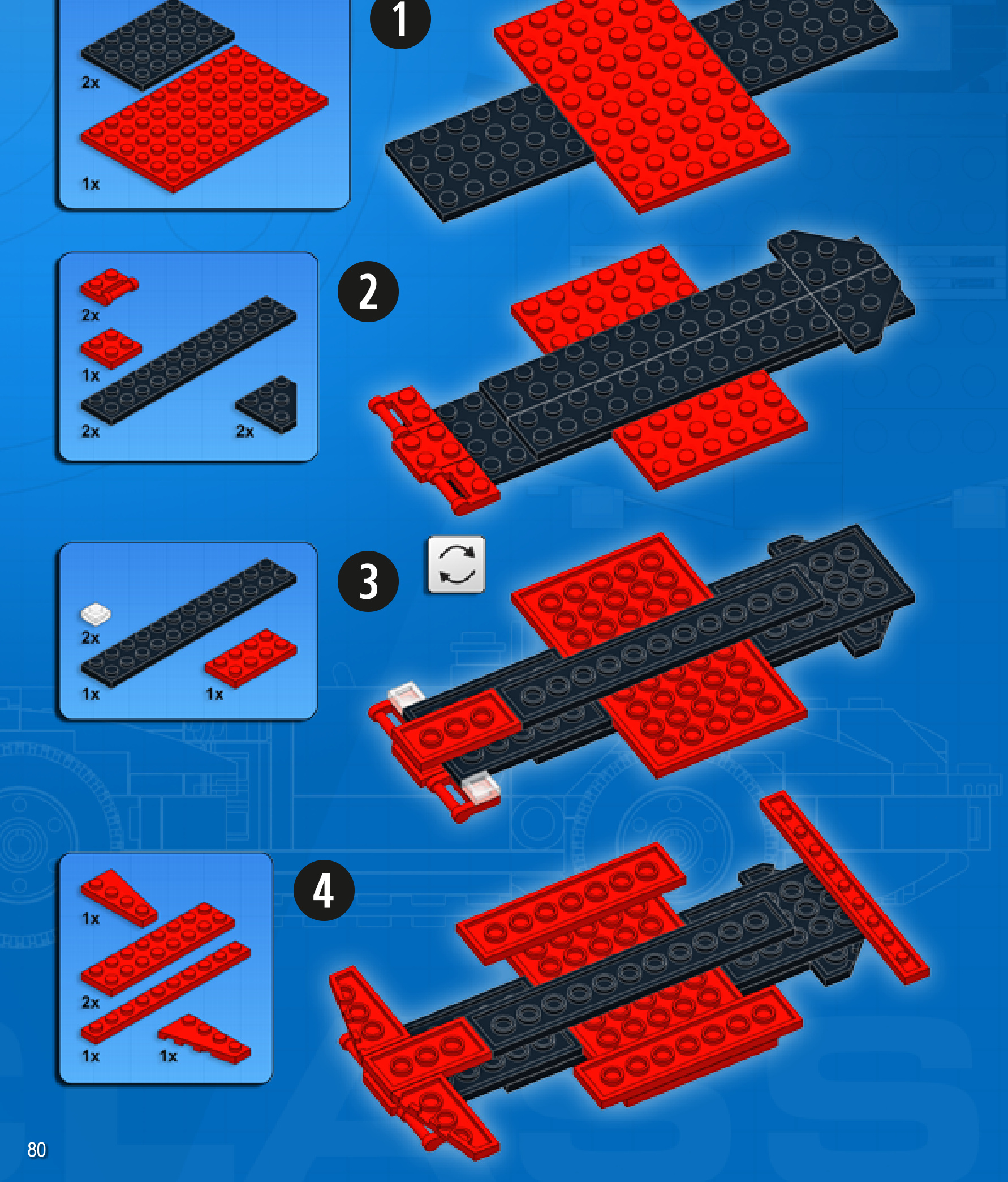

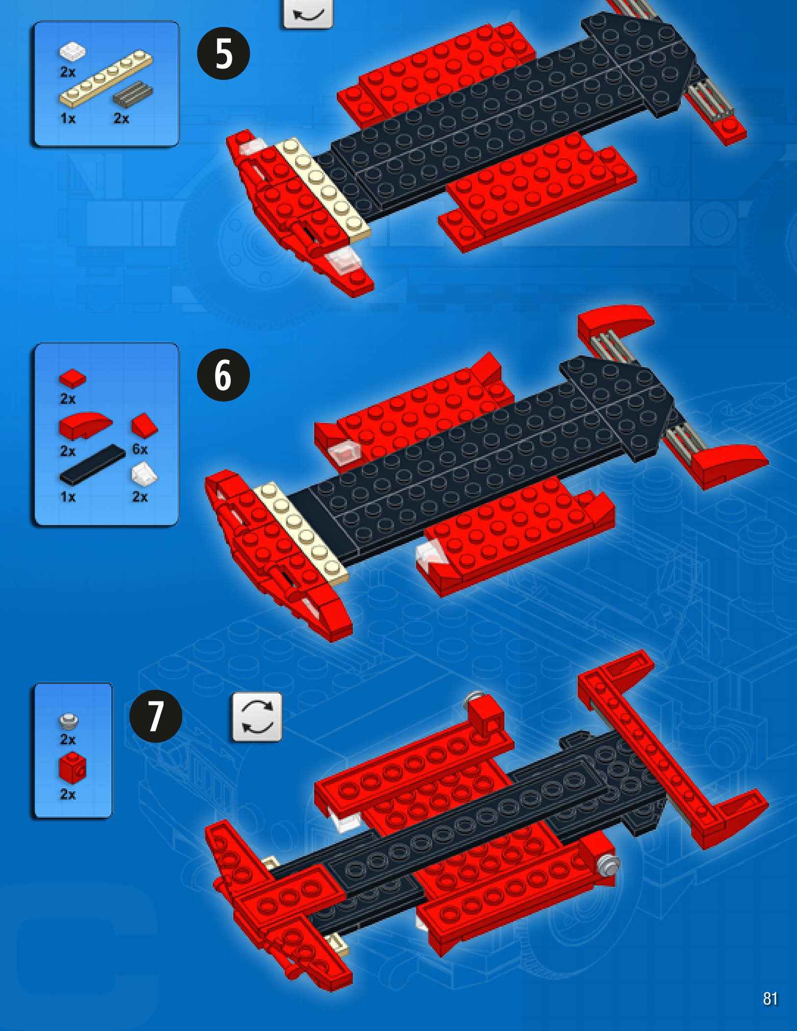
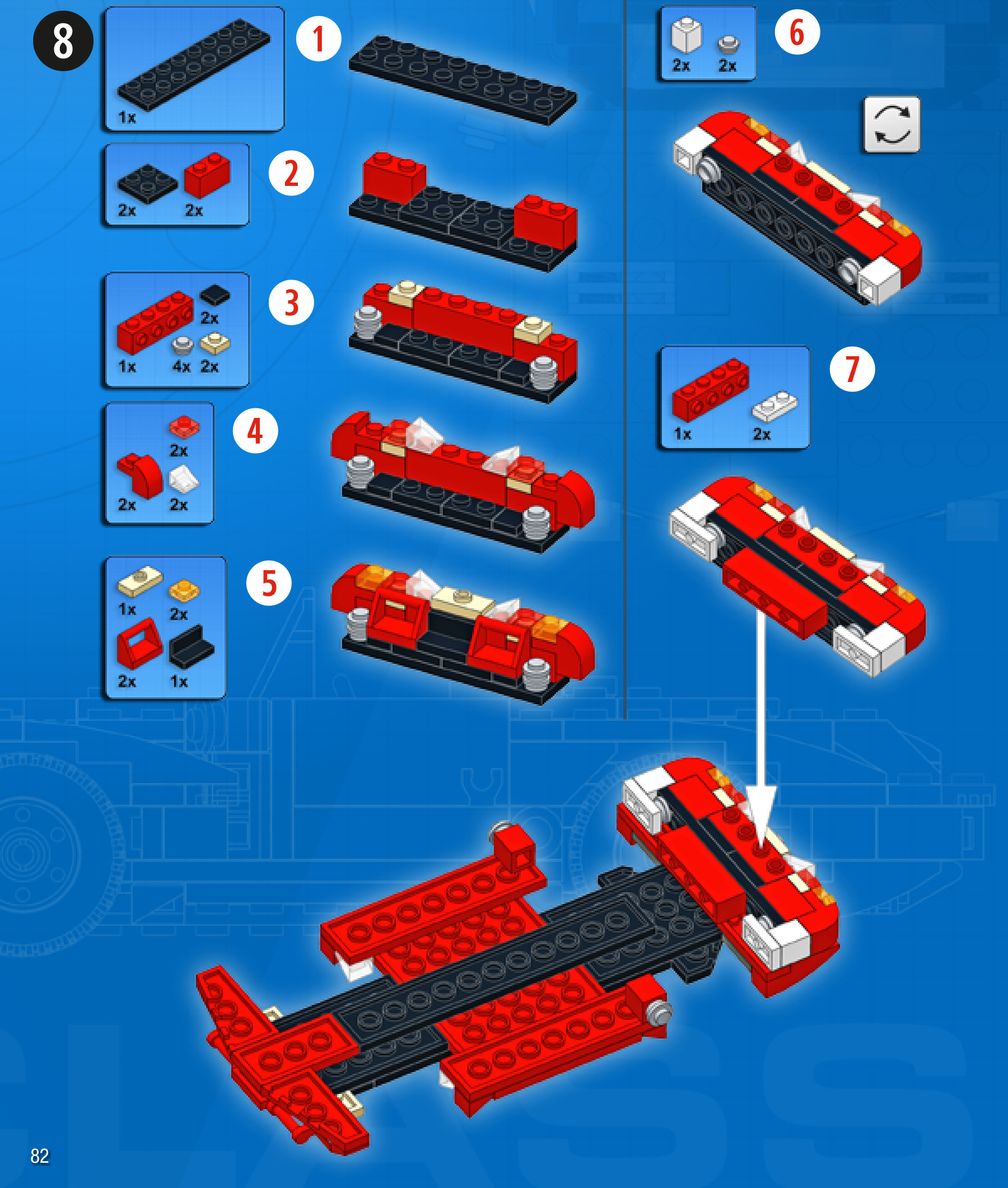
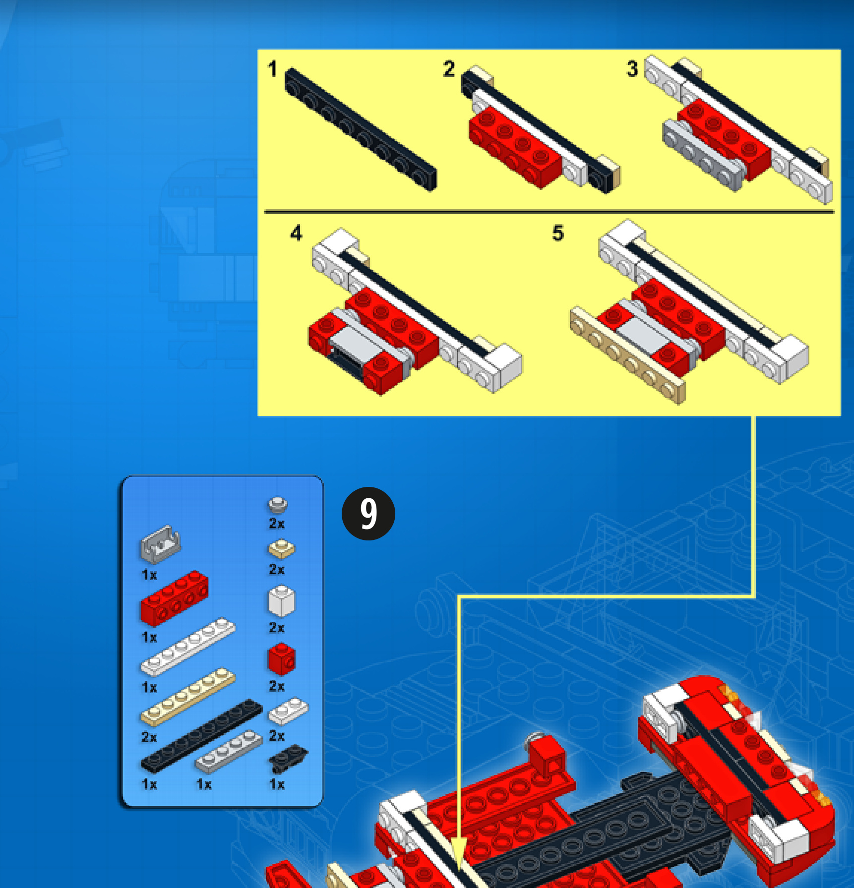

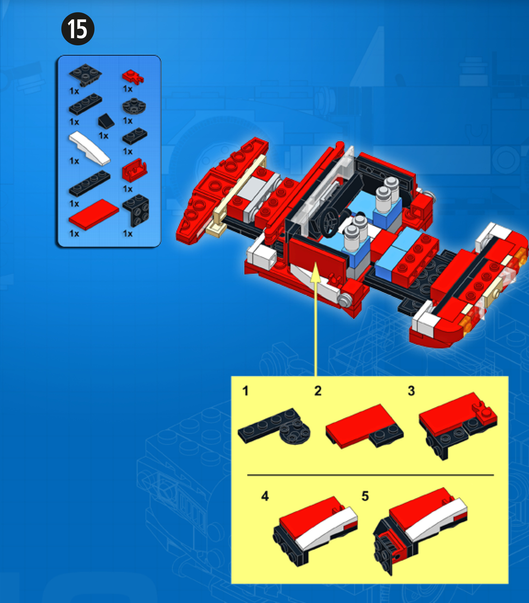
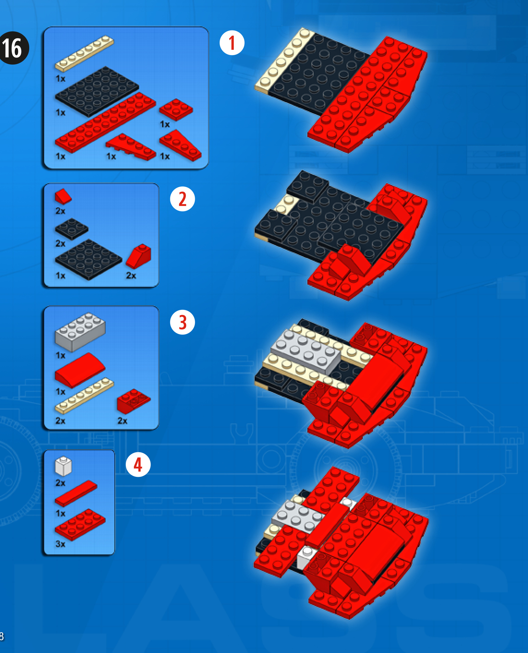

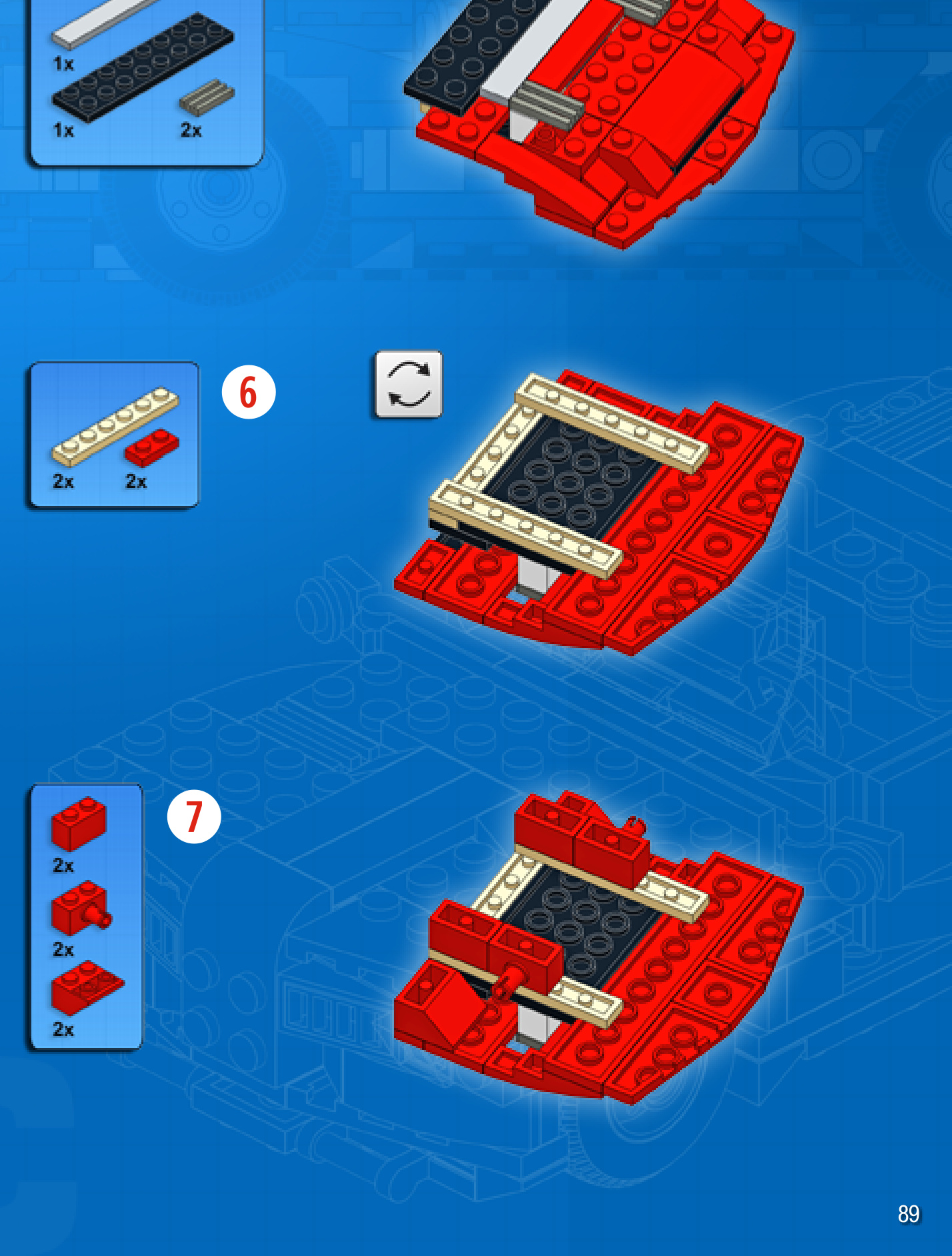
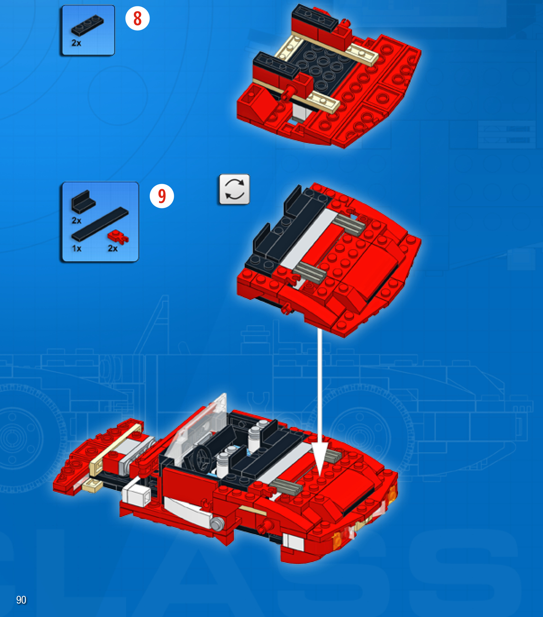

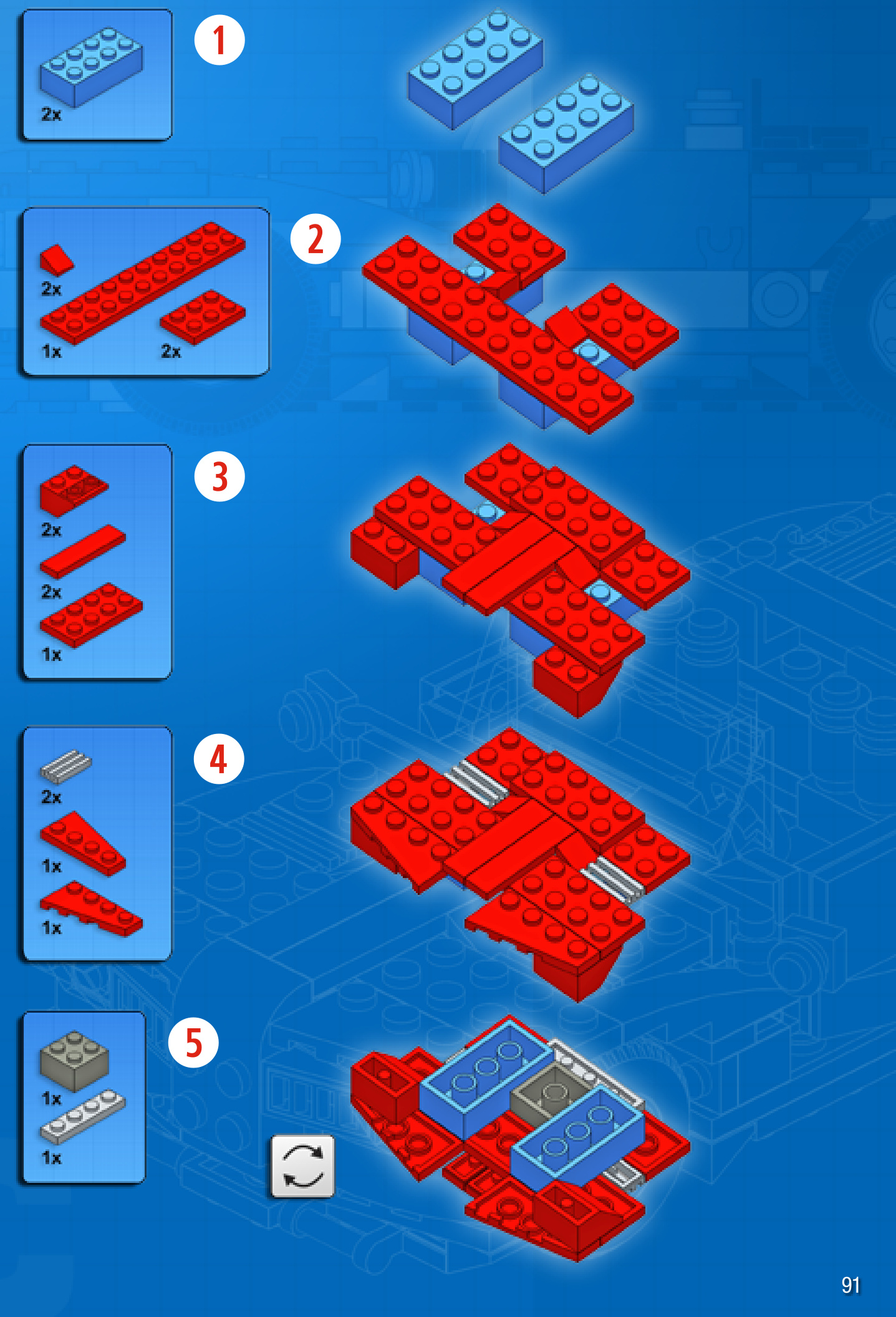
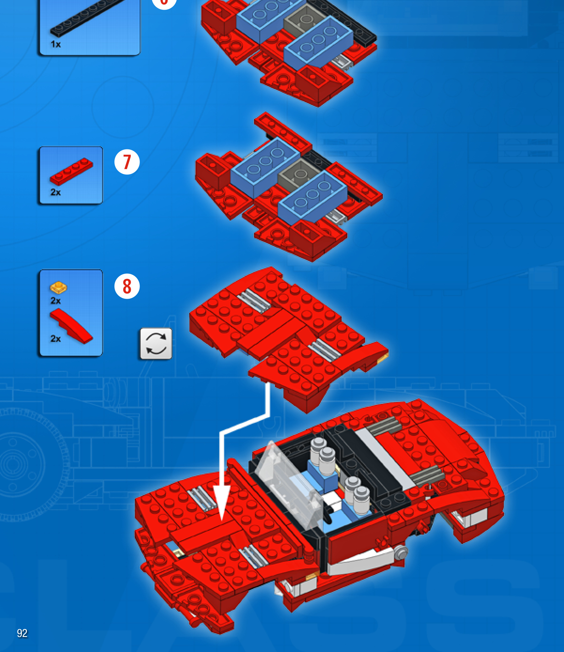

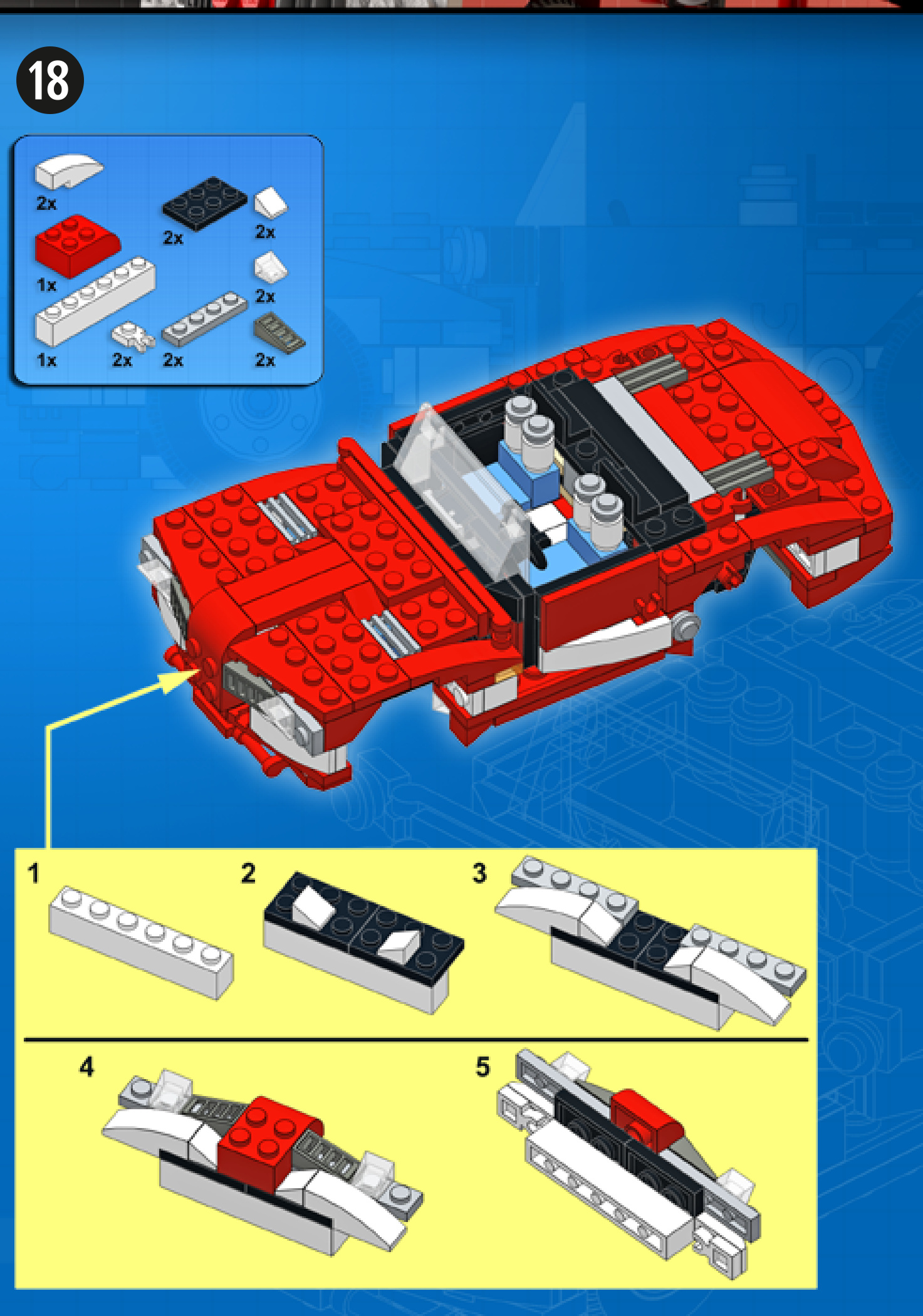
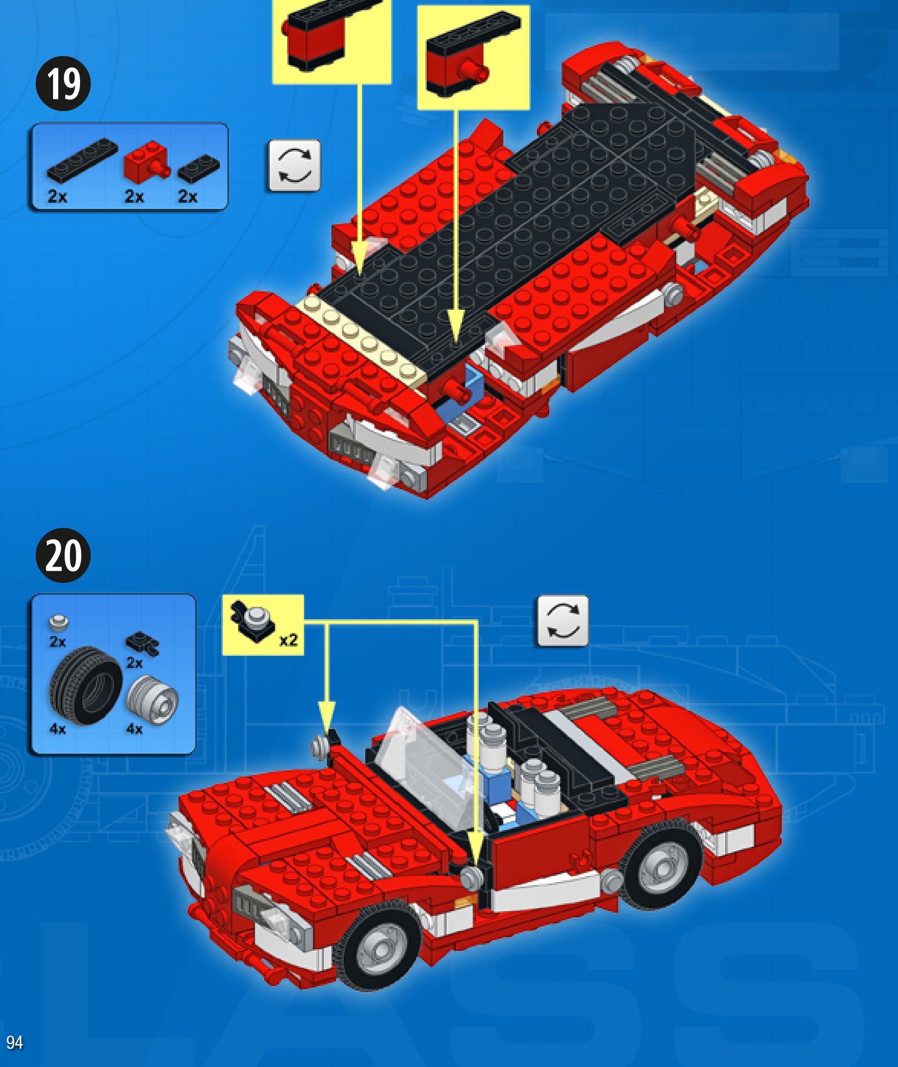
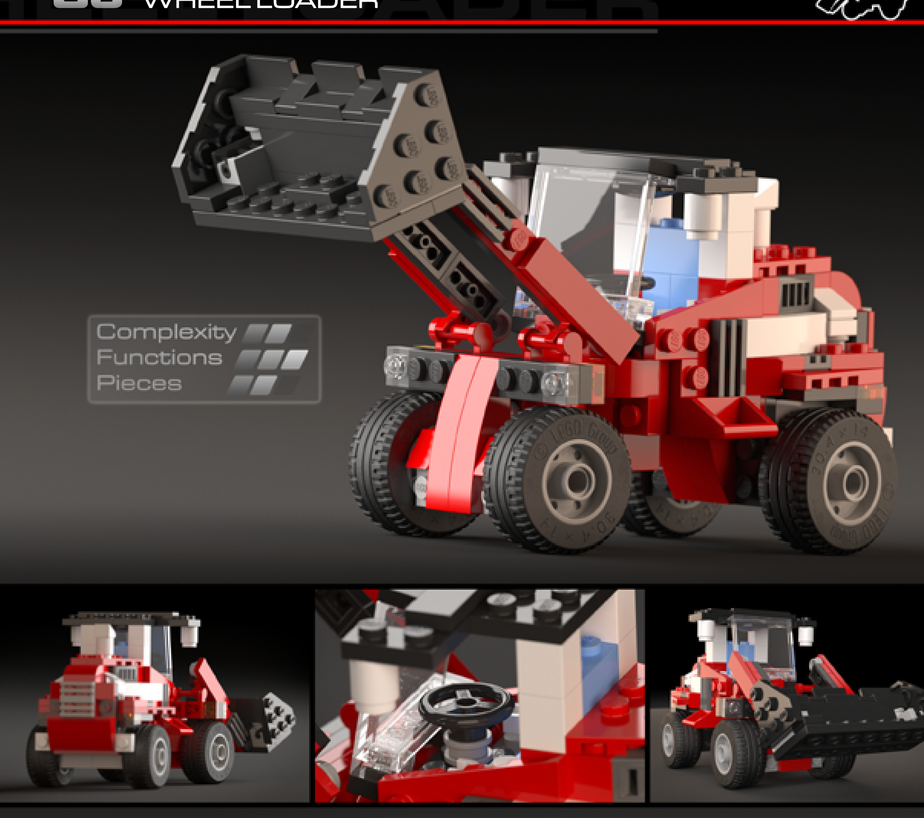
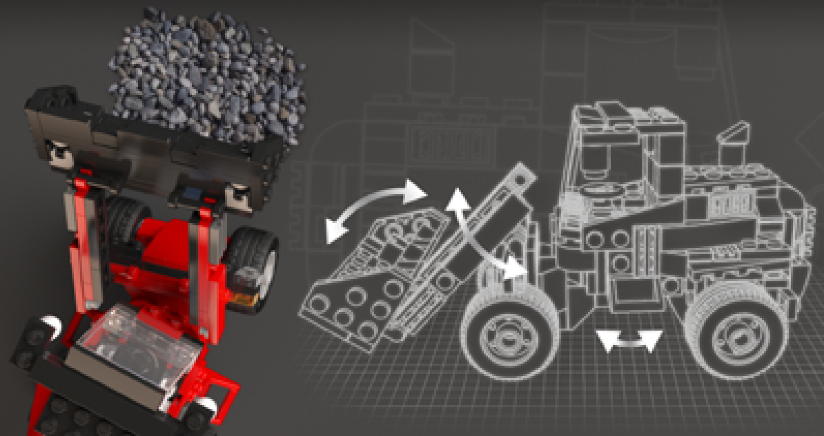
WHEELLOADER
Design notes: heavy-duty construction, centralcabin
Technical specifications: Dimensions (l xw× h): 21 ×10 × 11 studs Wheelbase: 9 studs Axle width front/rear: 8/8 studs
Features: articulated steering, arm elevation, tipping bucket
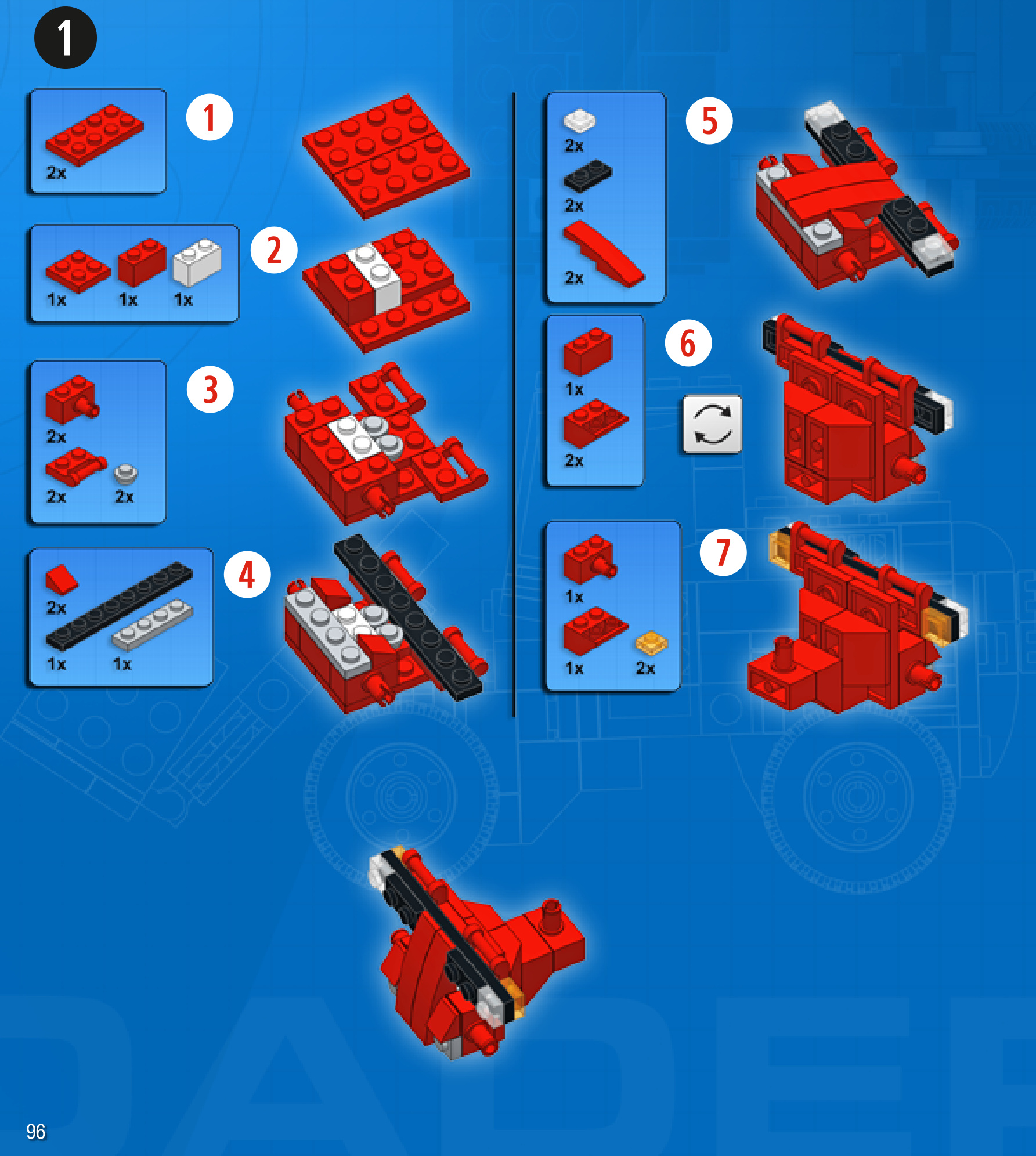
2
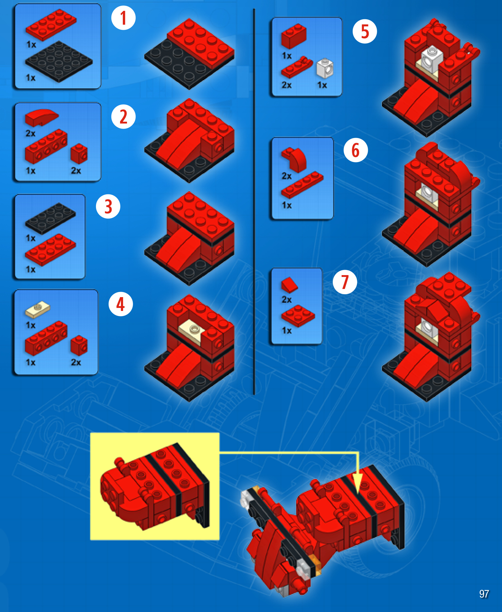
3
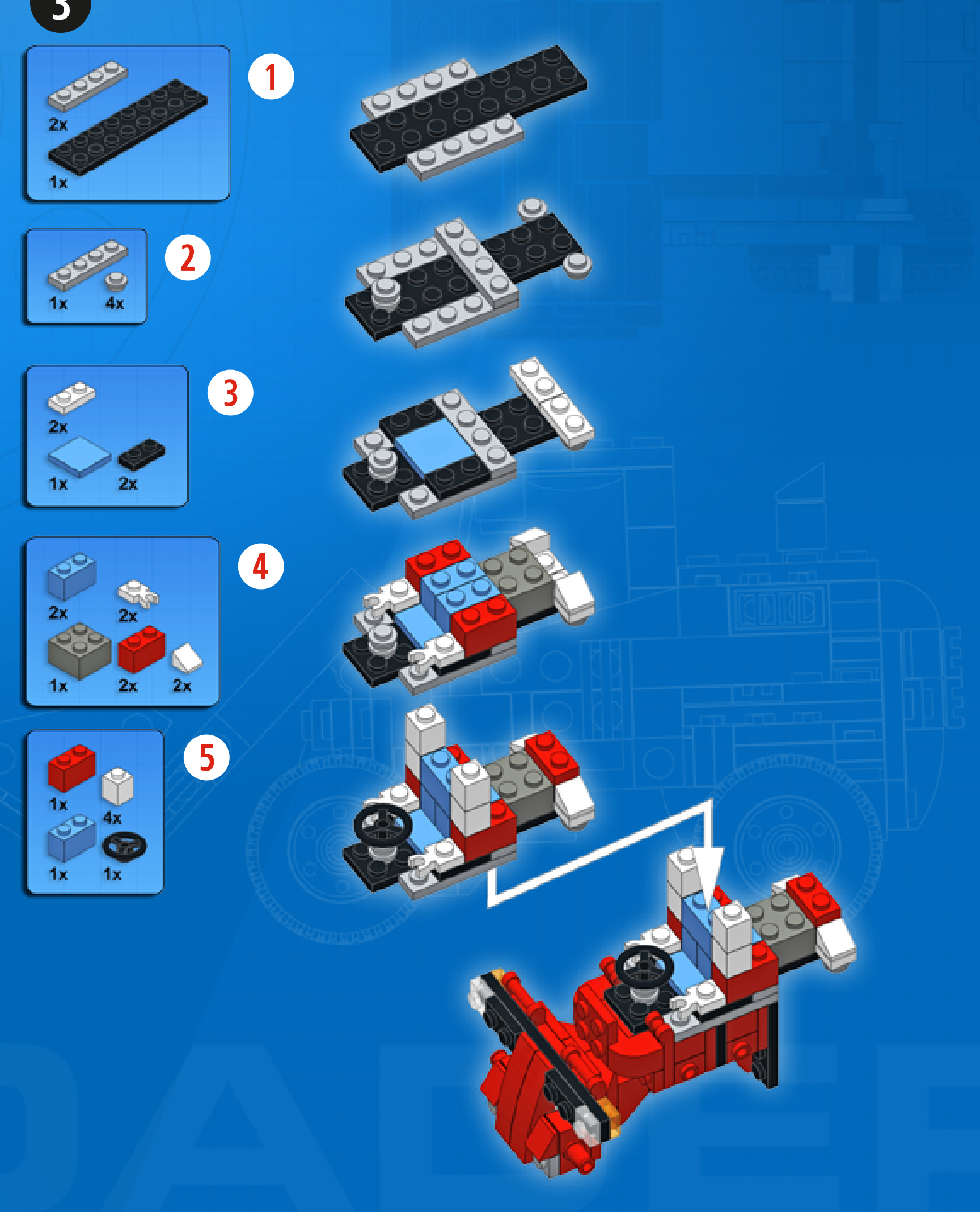
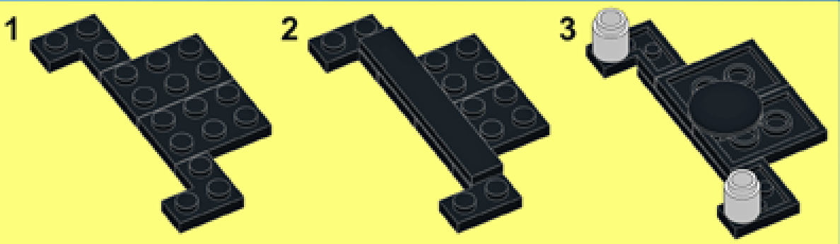
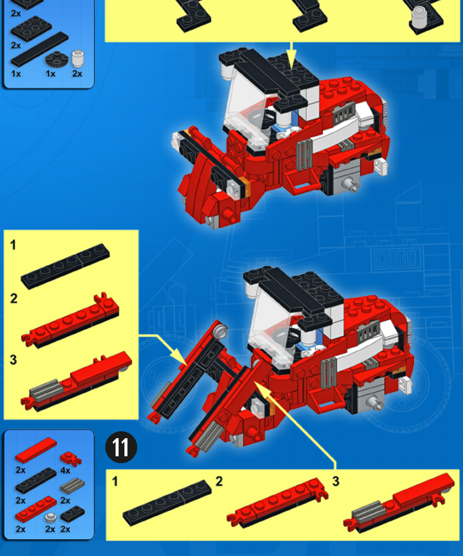
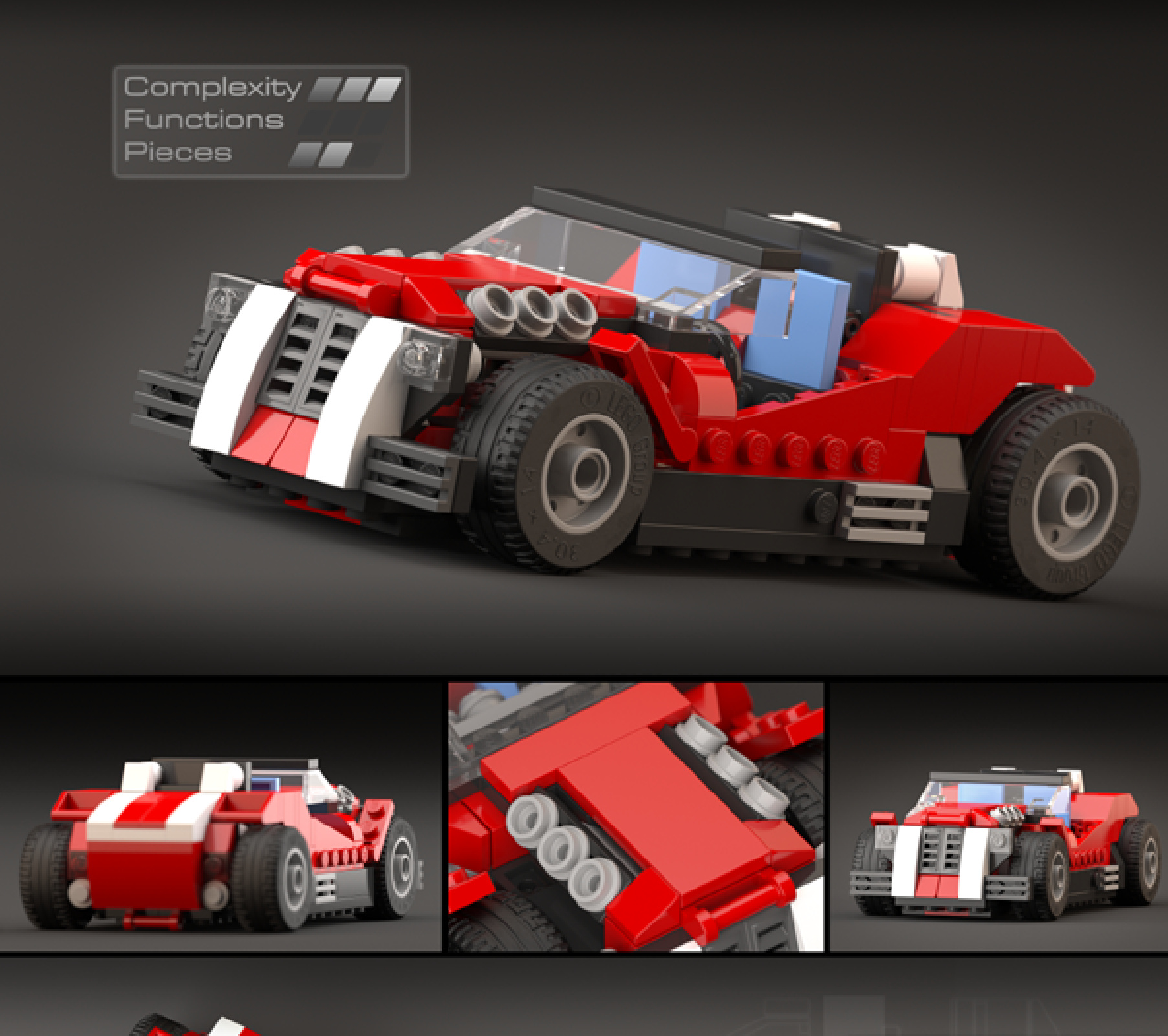
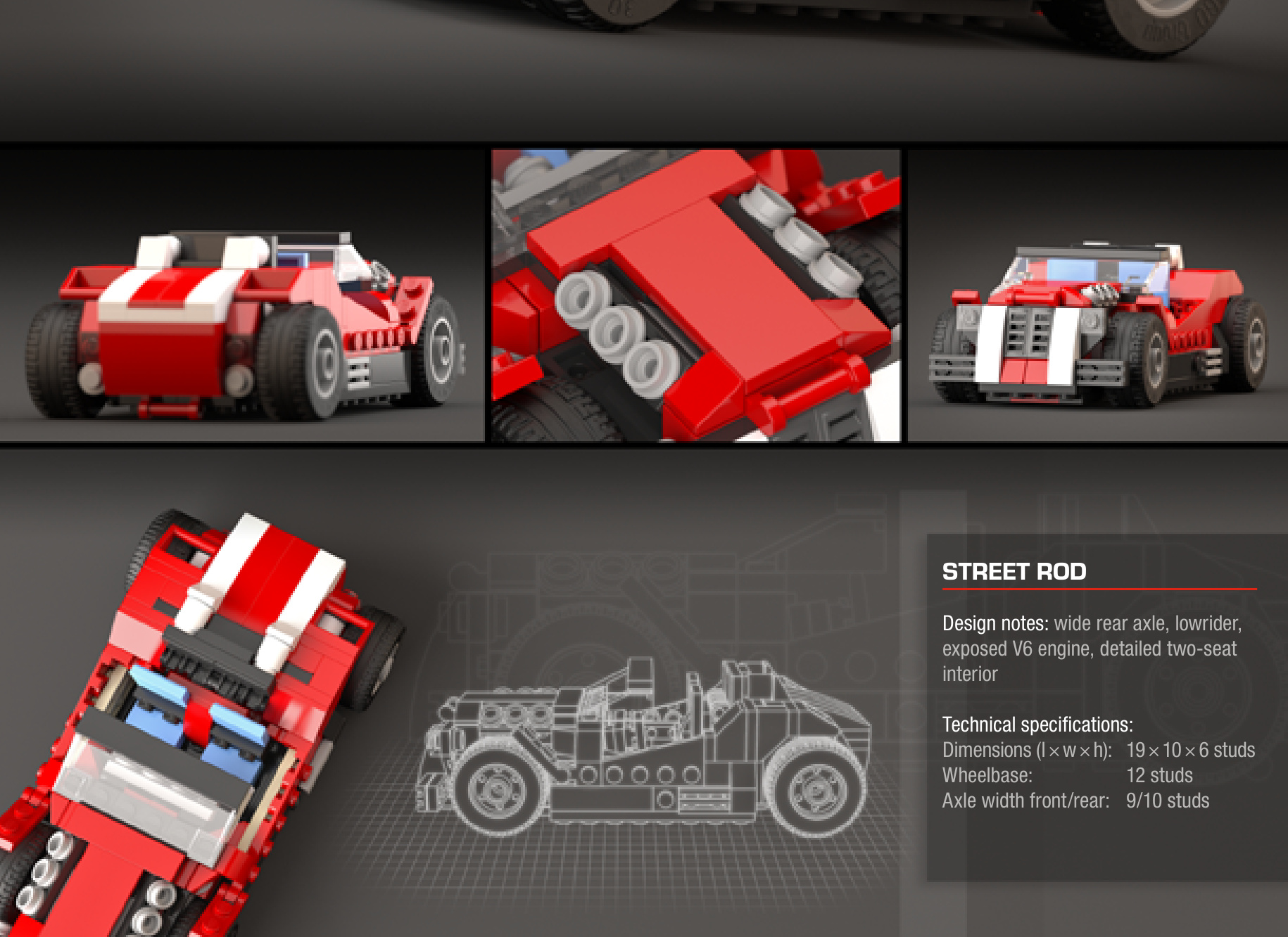
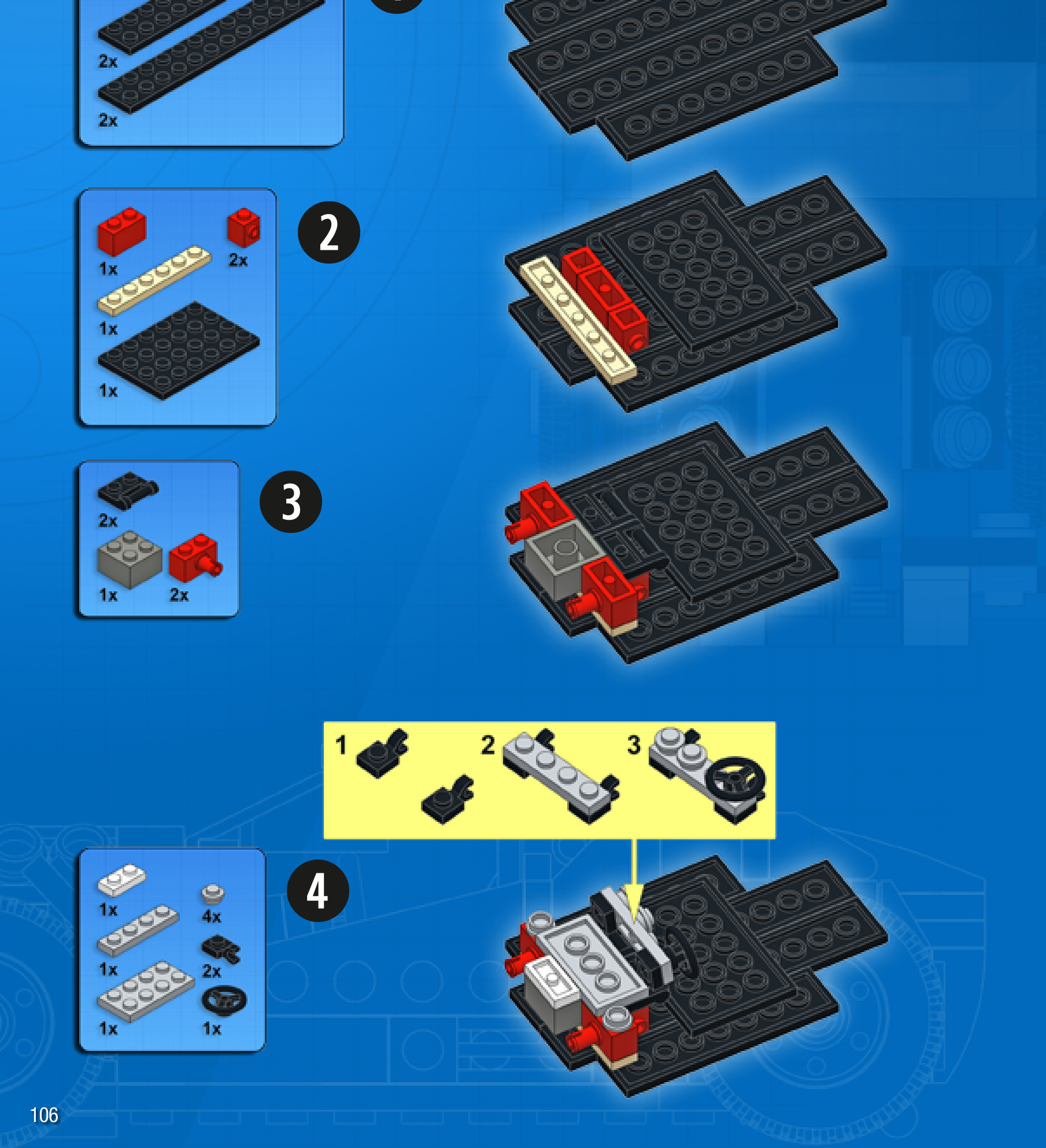
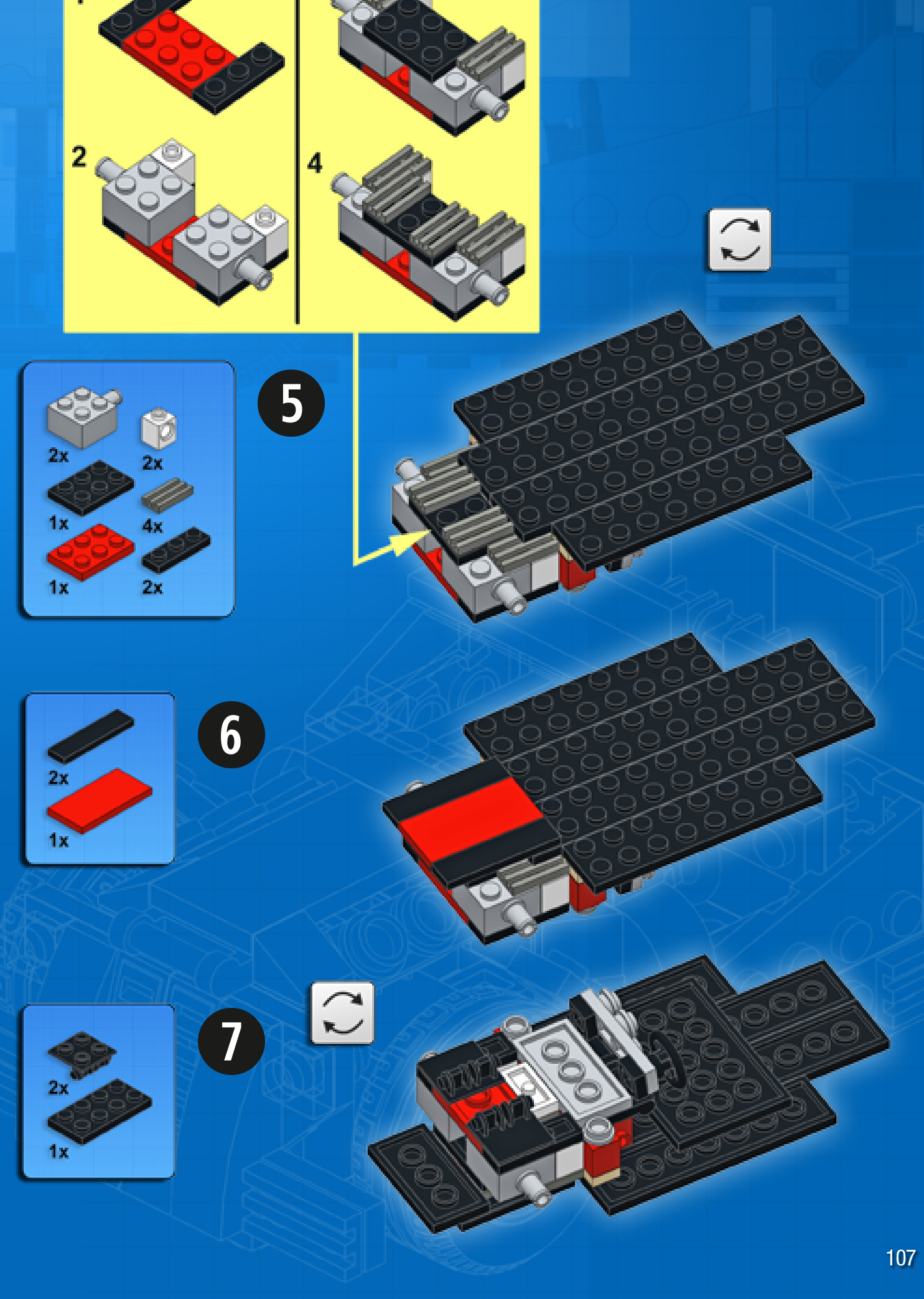
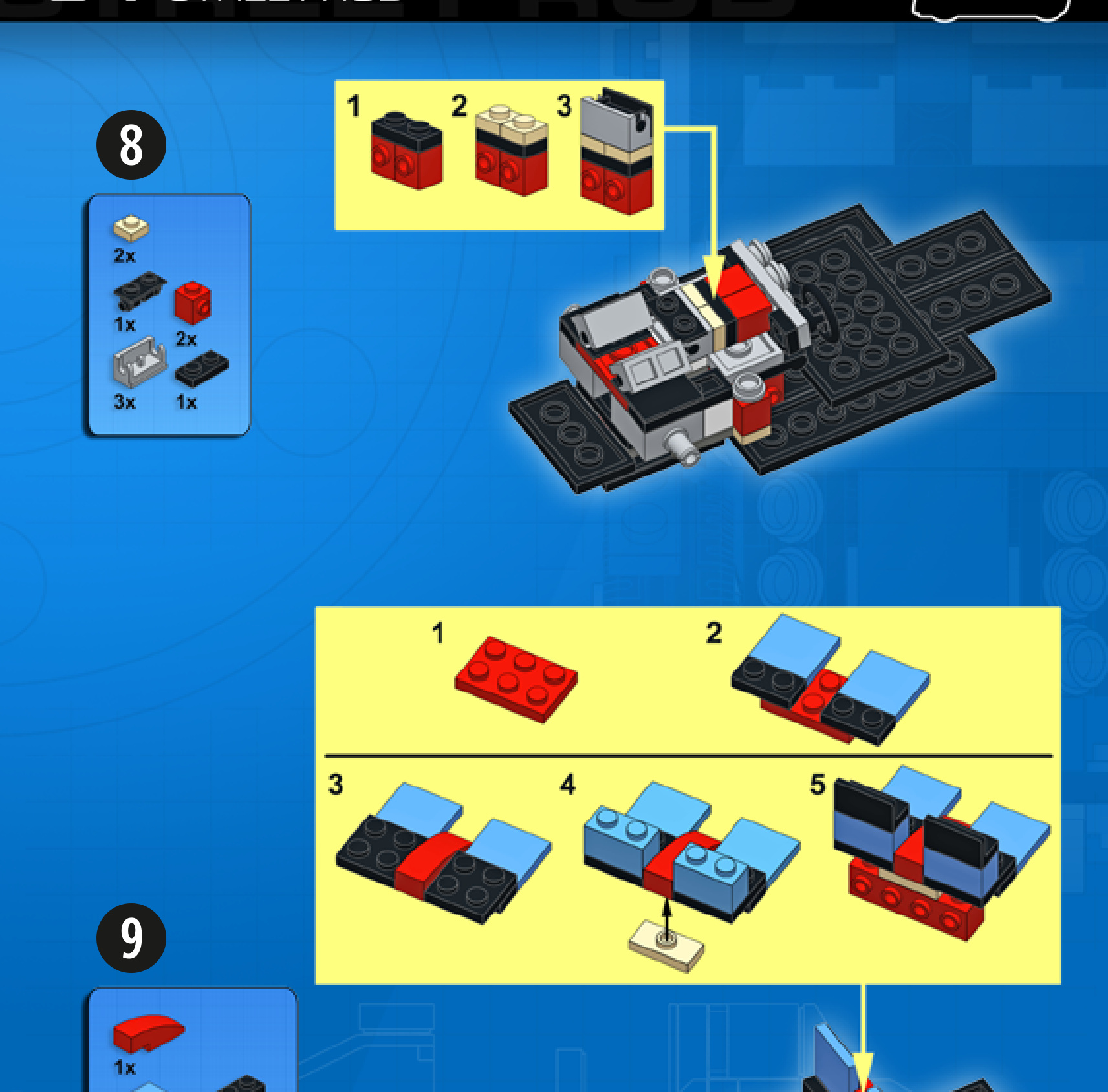

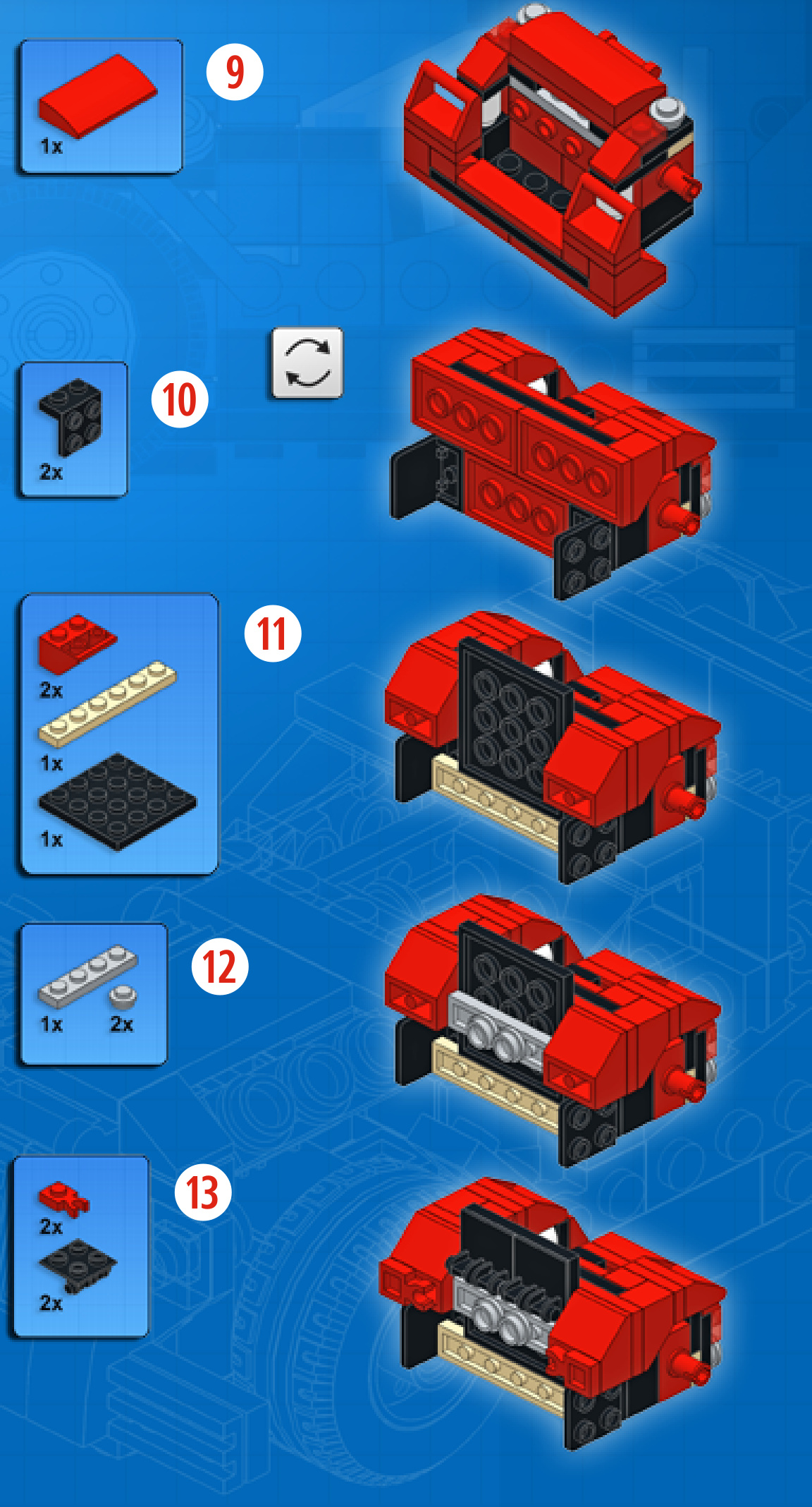
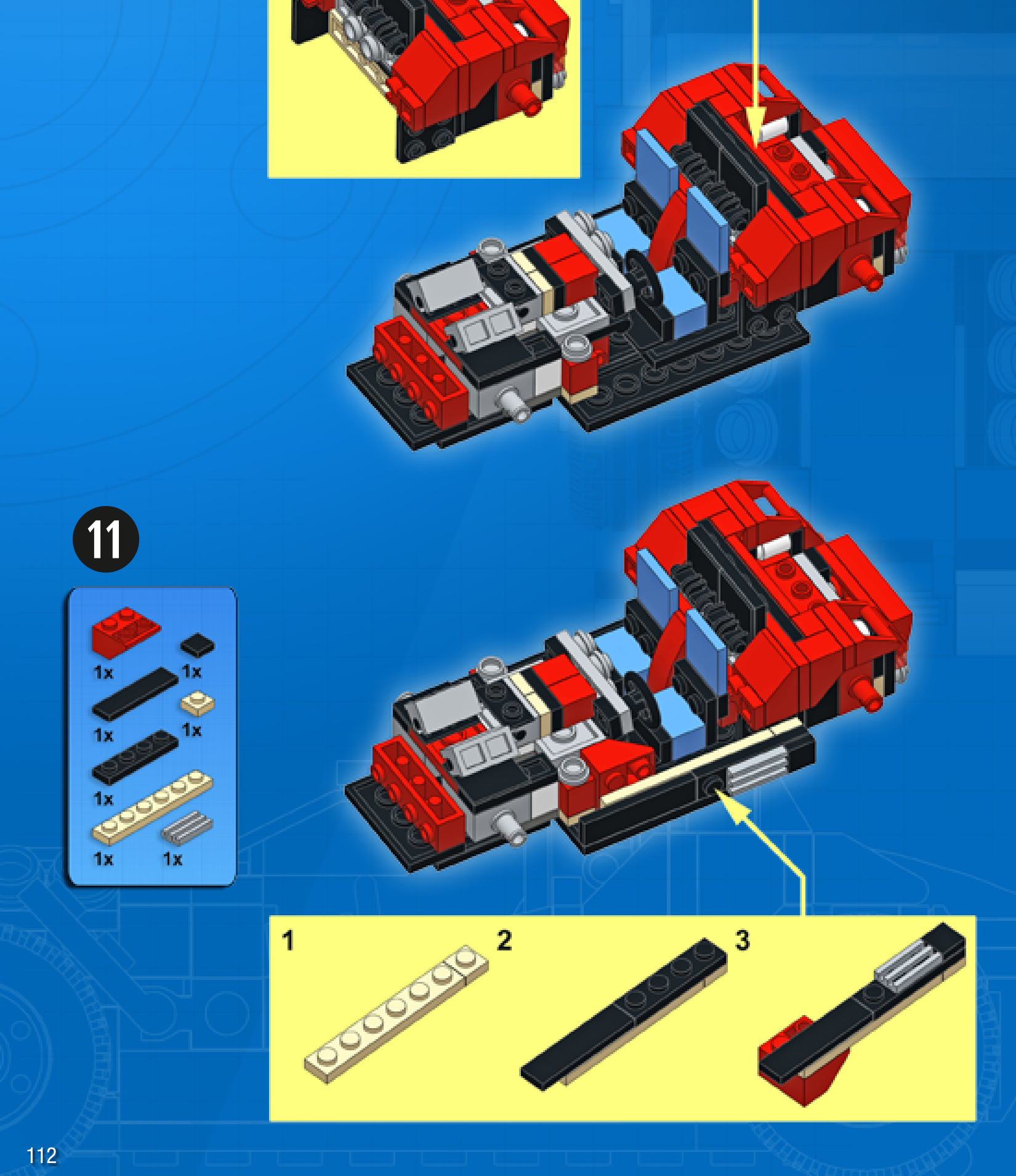
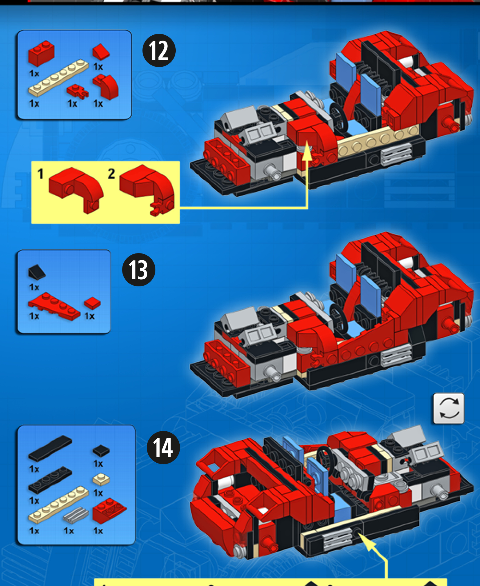
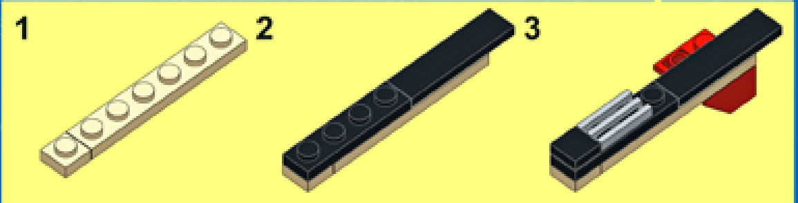
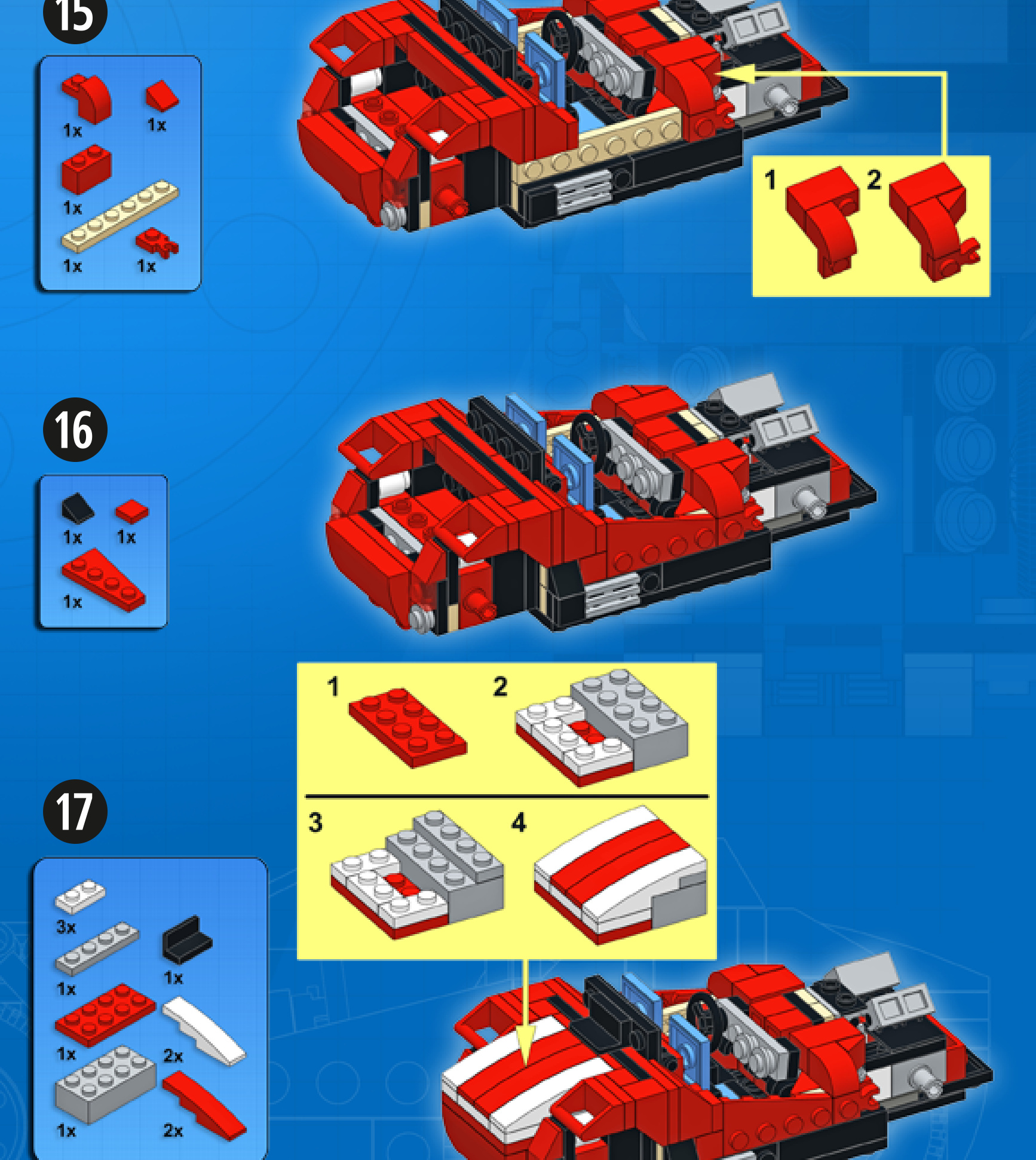
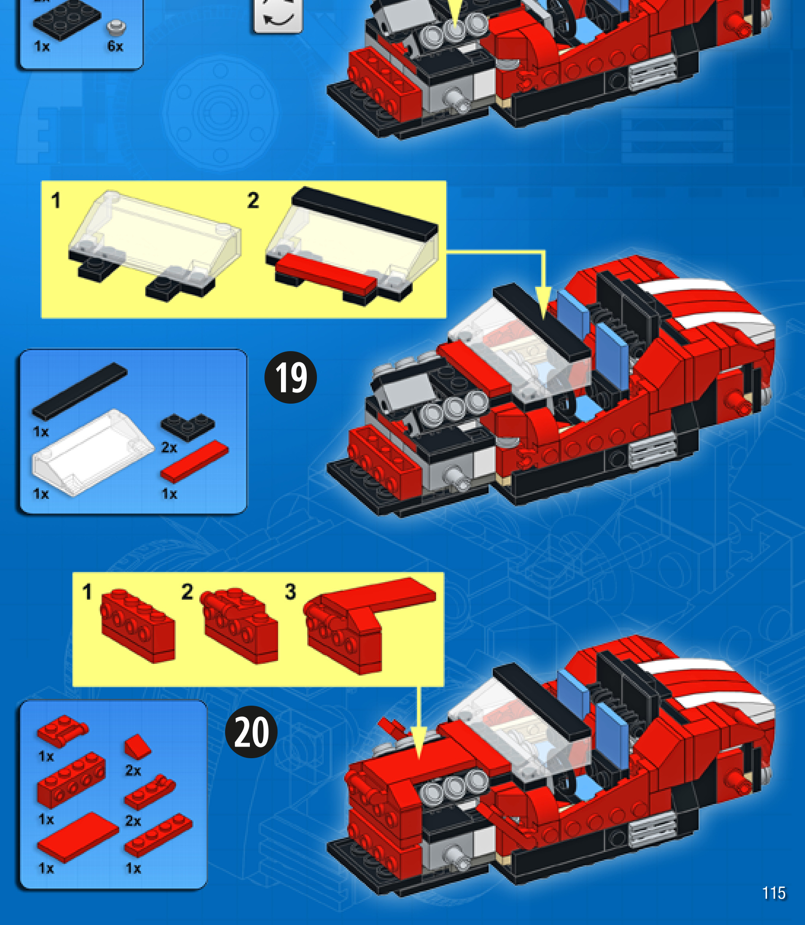
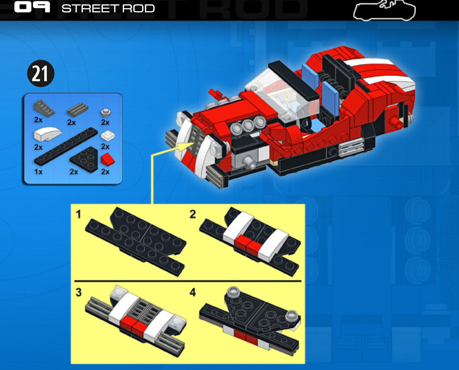
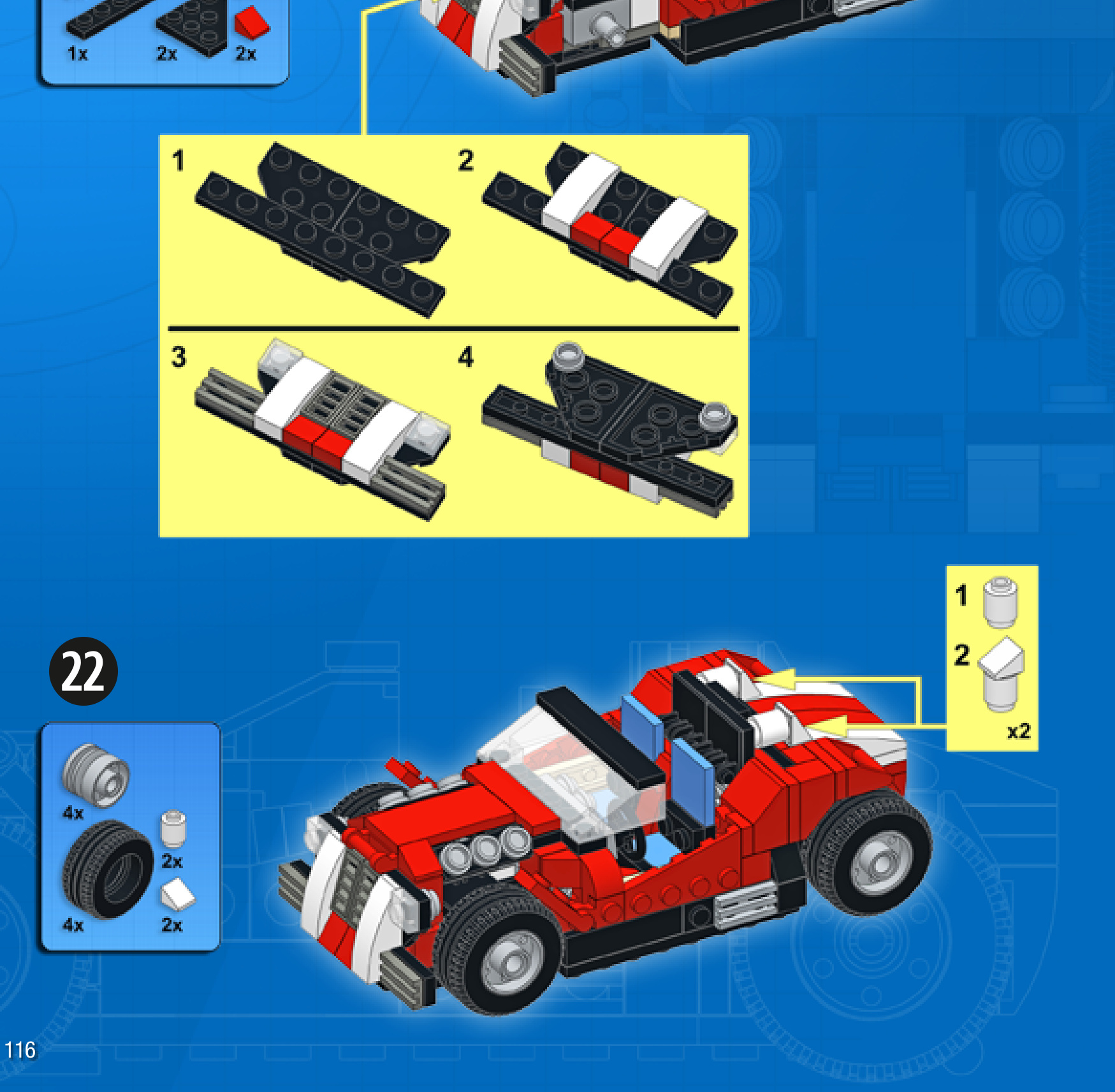
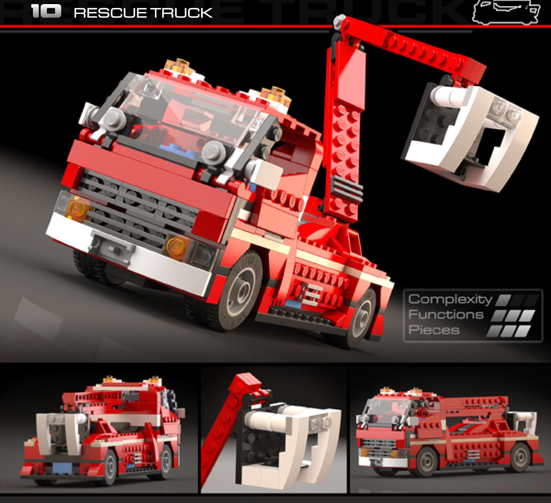
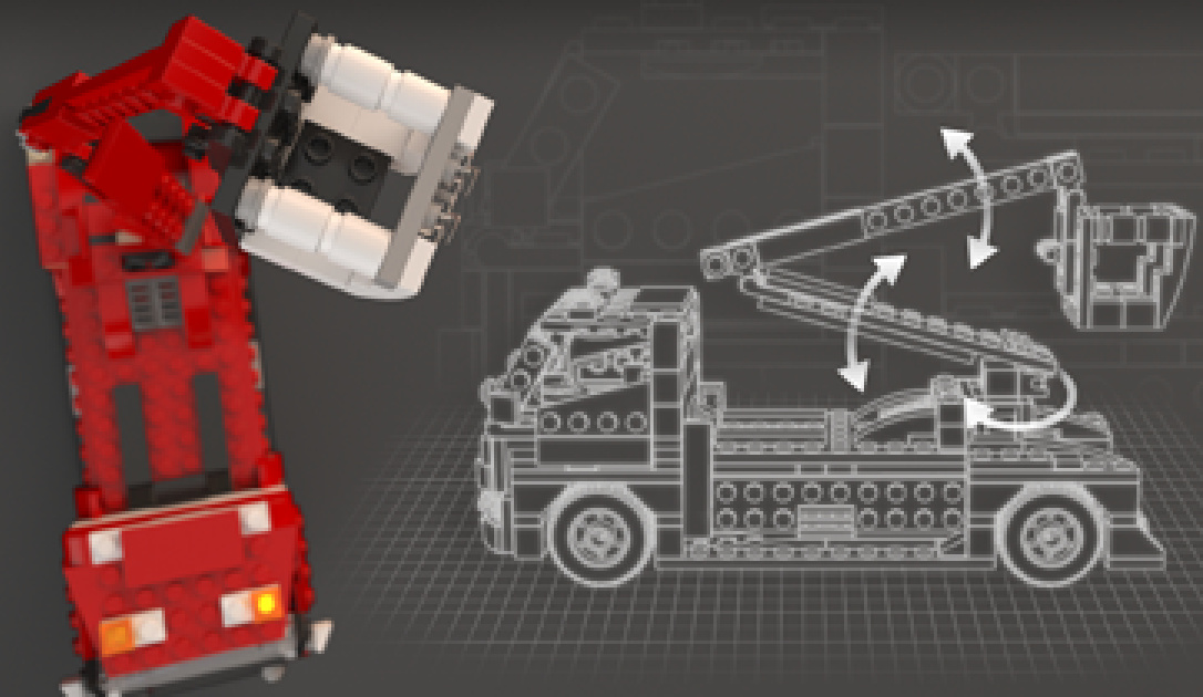
RESCUETRUCK
Design notes: long wheelbase, cherry picker arm with bucket, massive front grille, hazard lights
Technical specifications: Dimensions (I×w× h): Wheelbase: Axlewidthfront/rear:
26 ×10 × 11 studs
16 studs
8/8 studs
Features: boom rotation, boom elevation
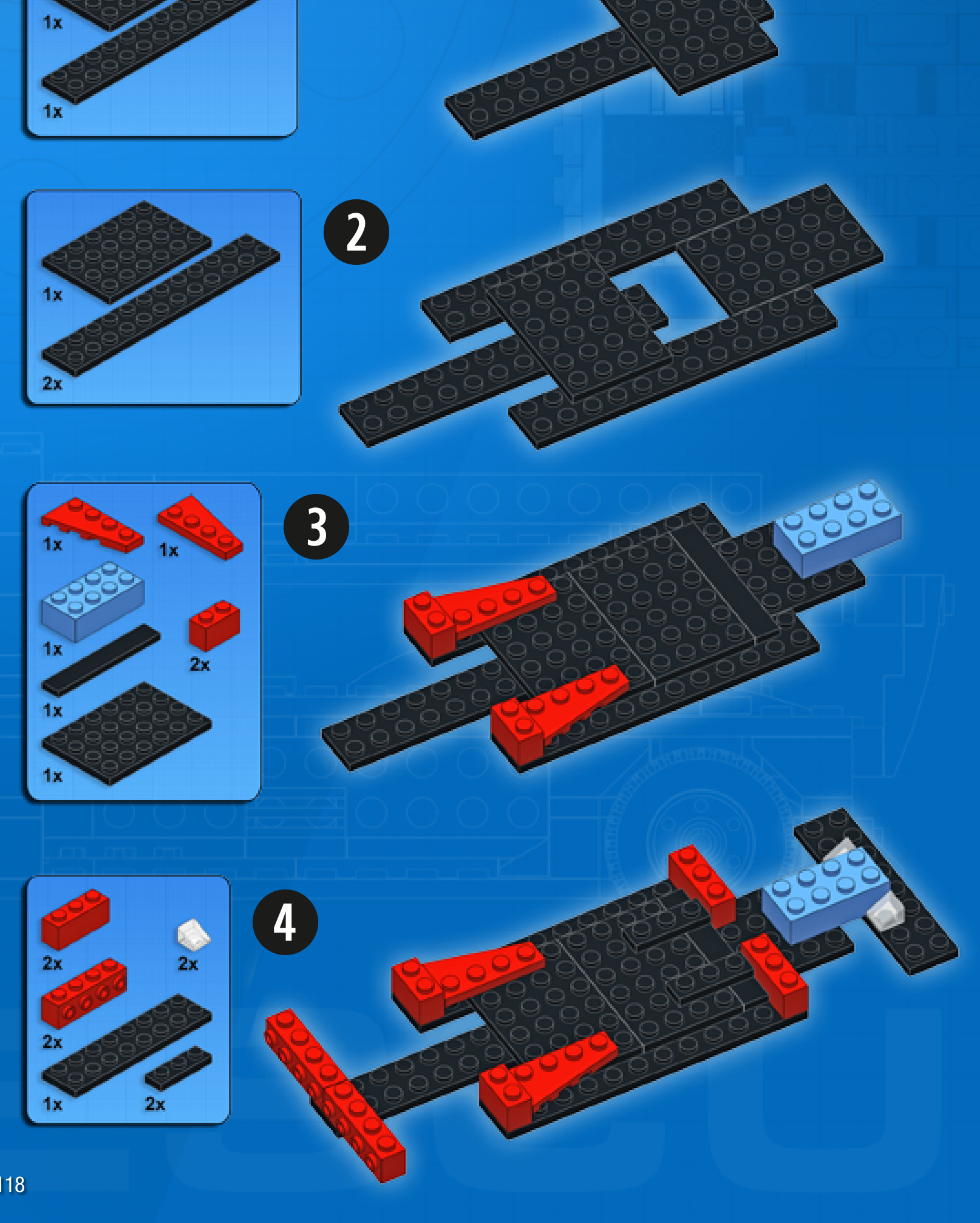
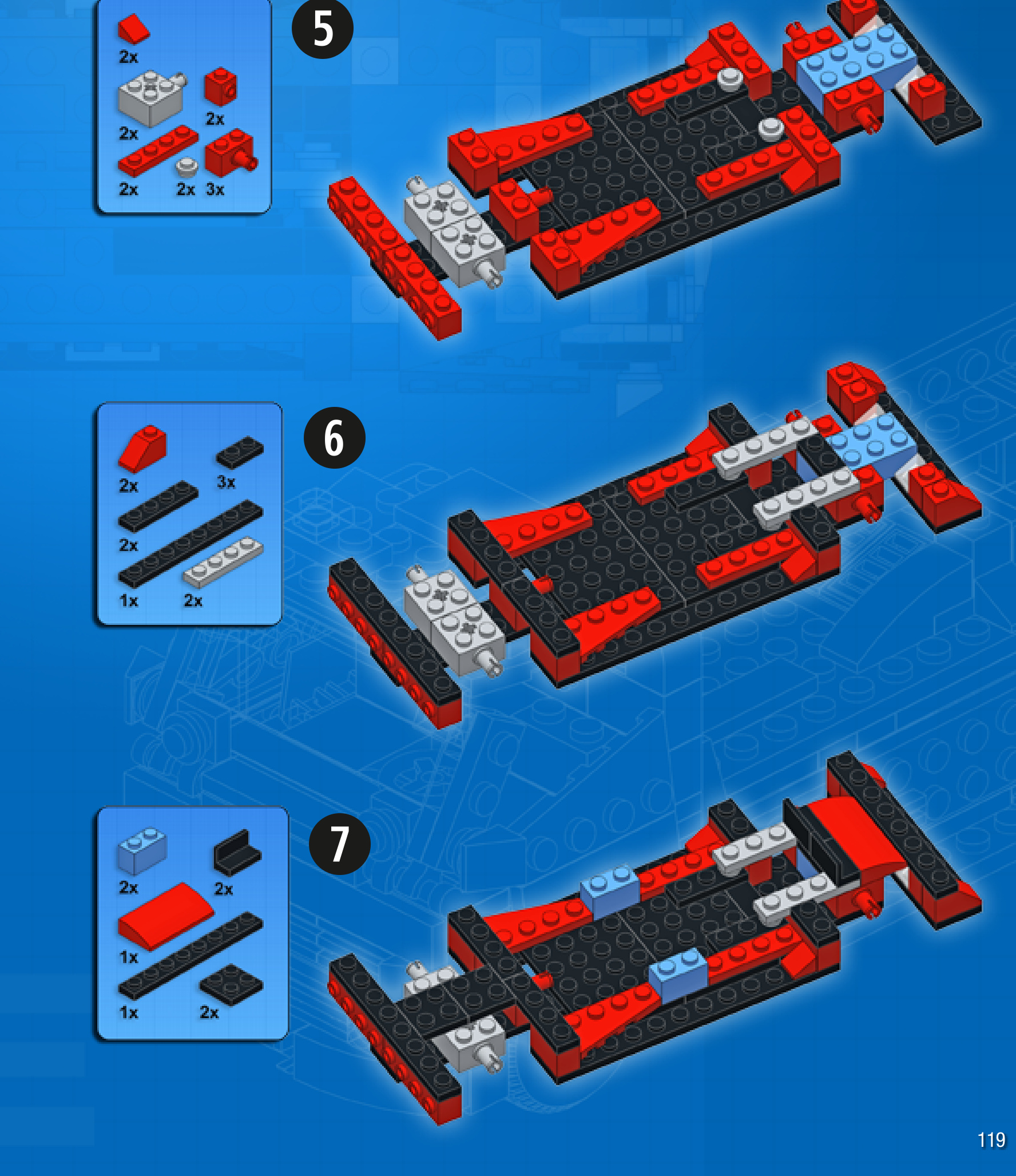
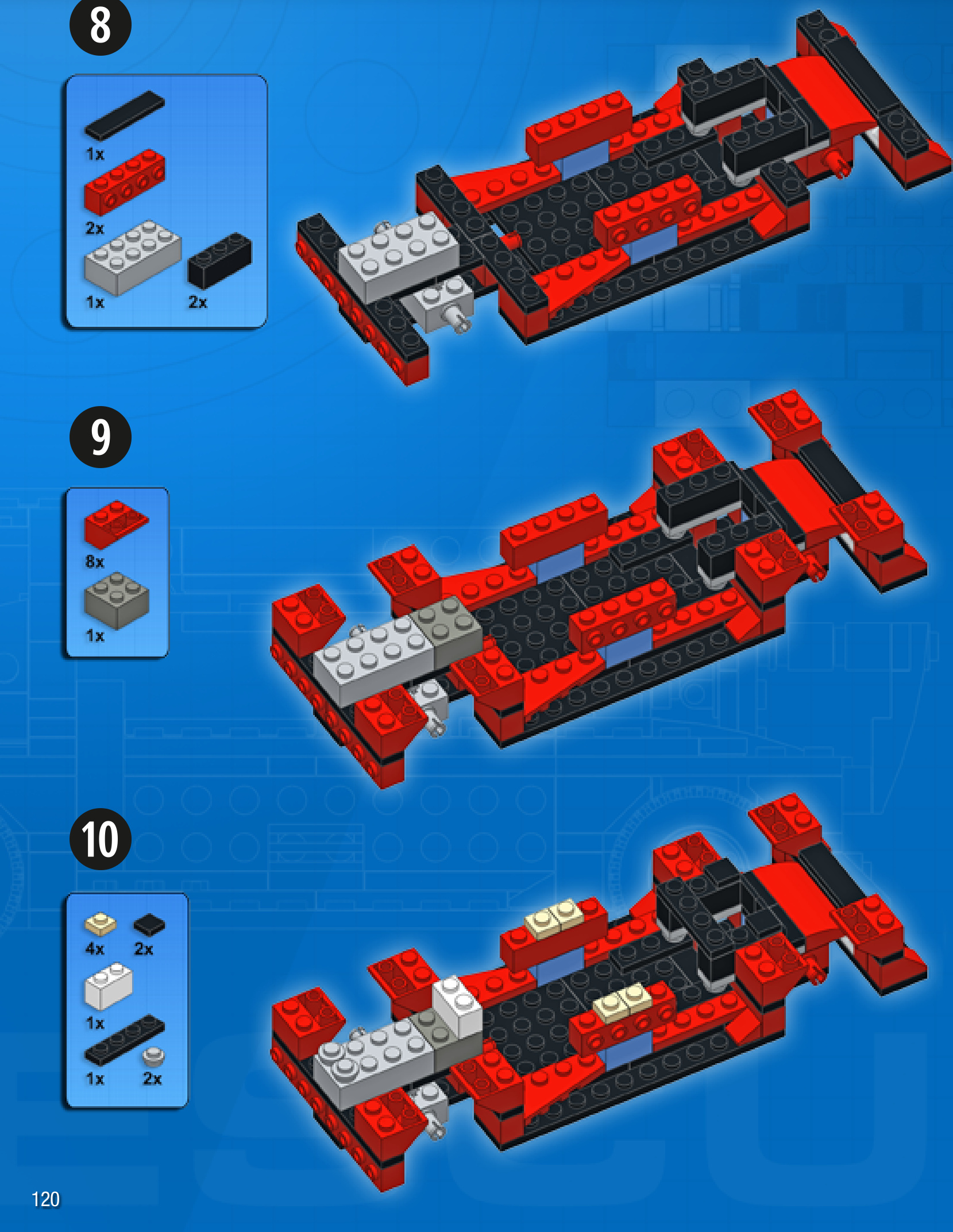

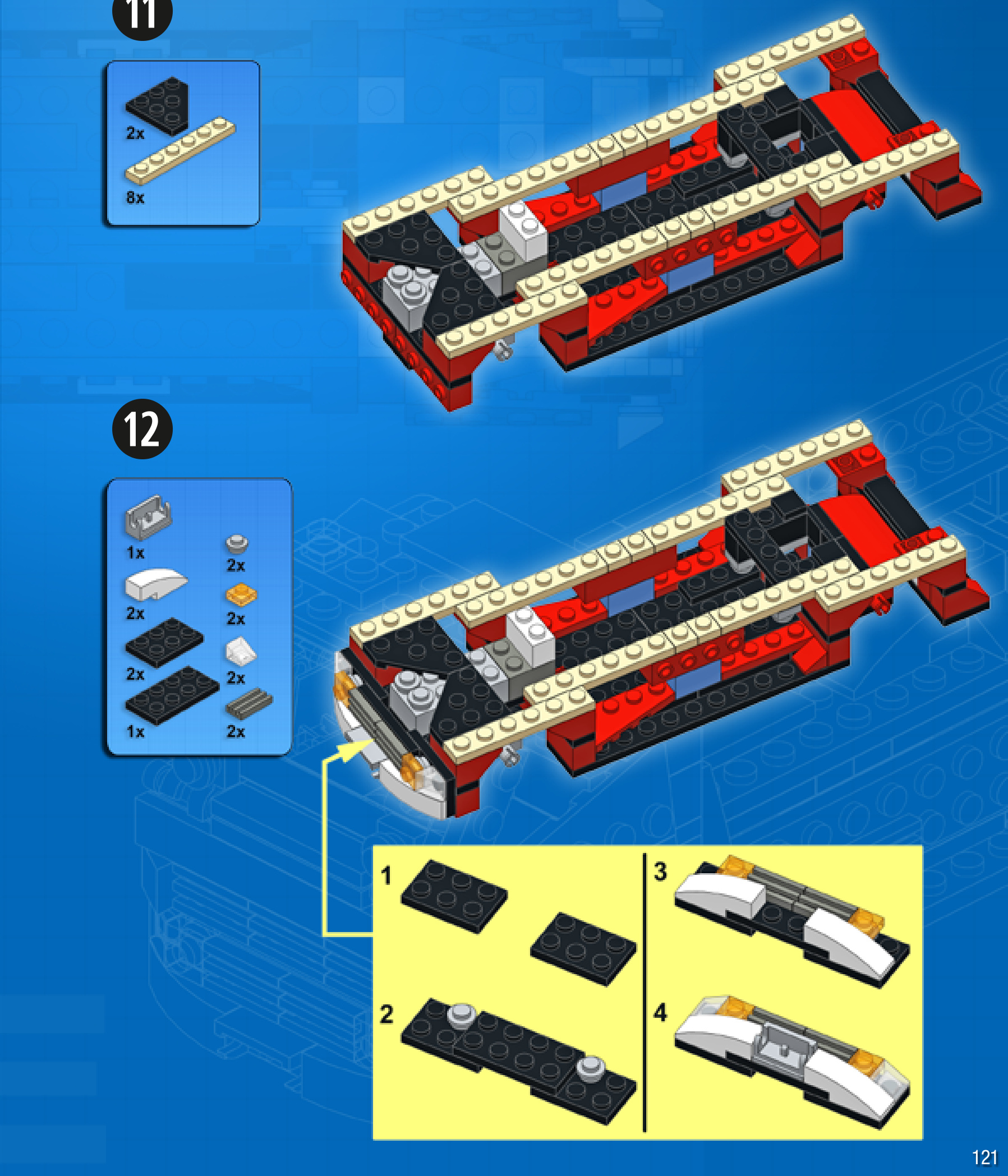
13
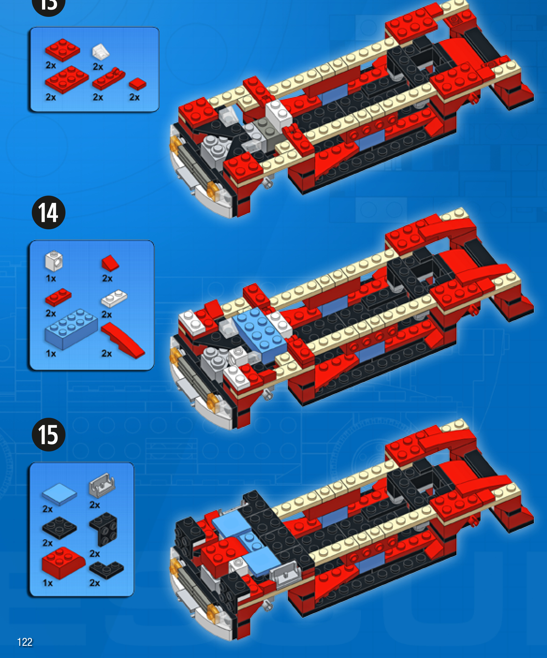

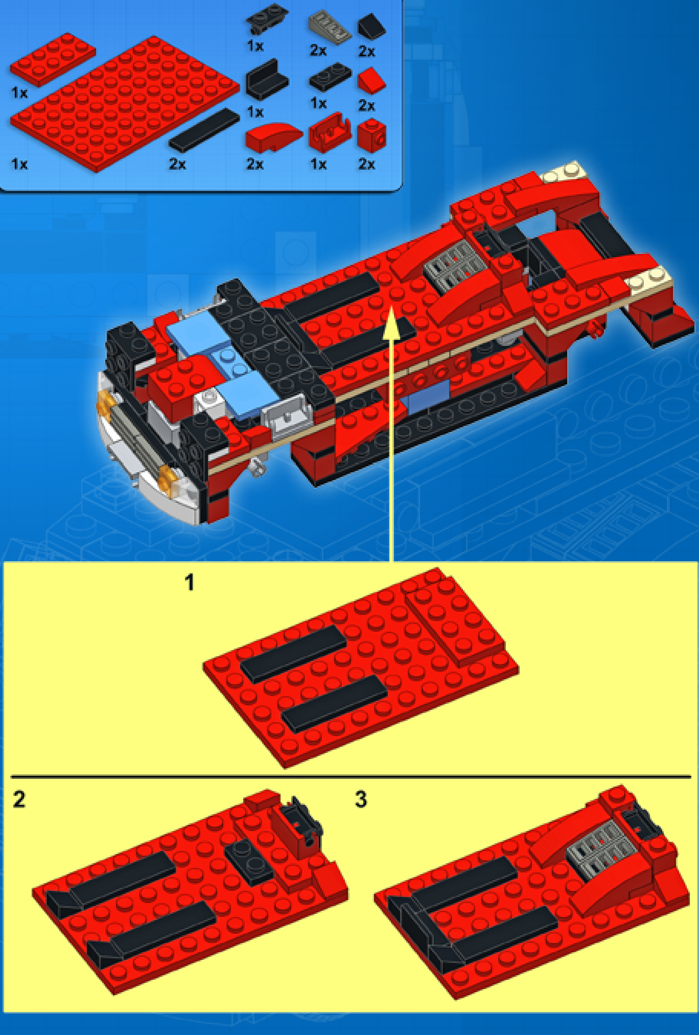
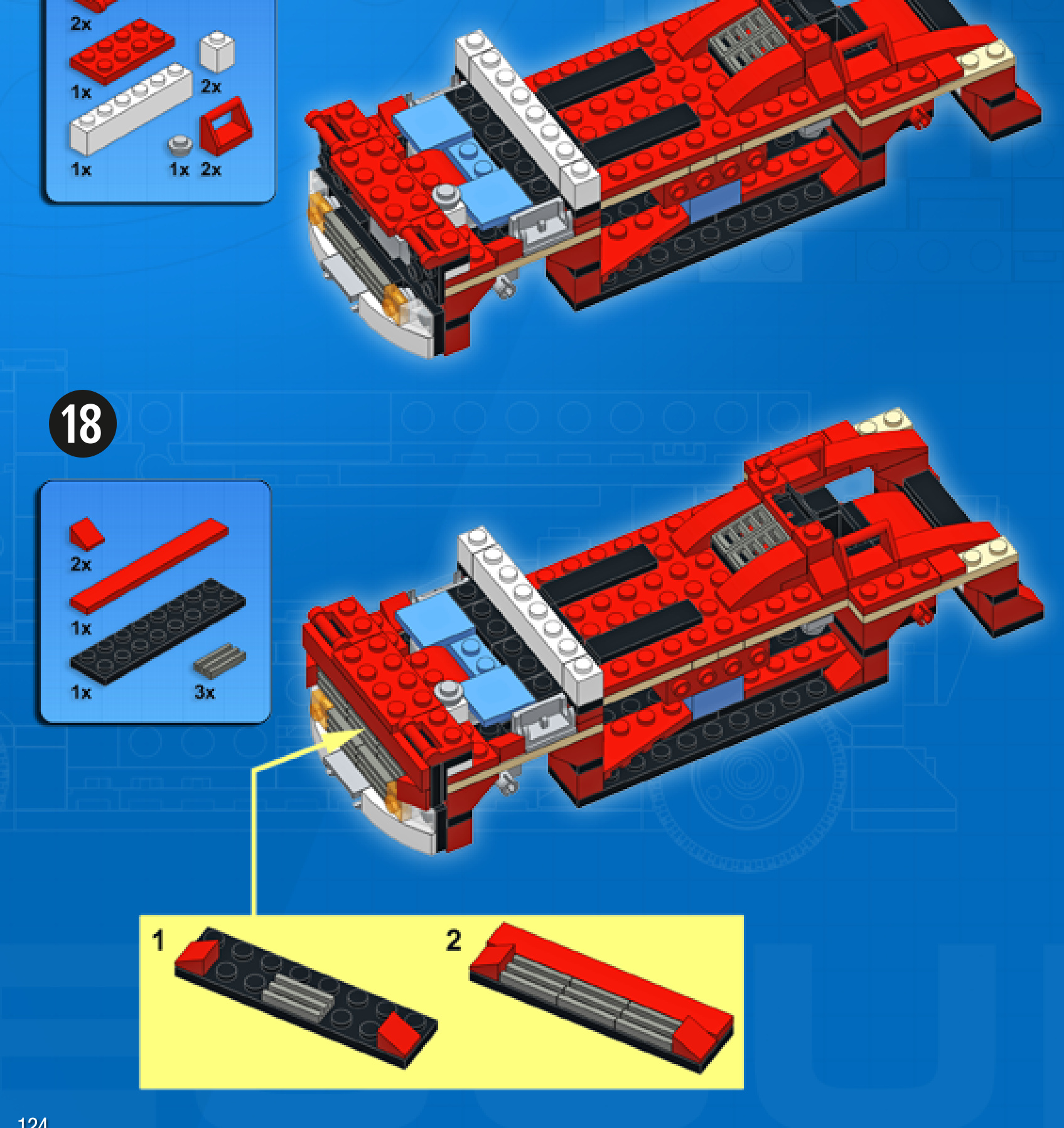

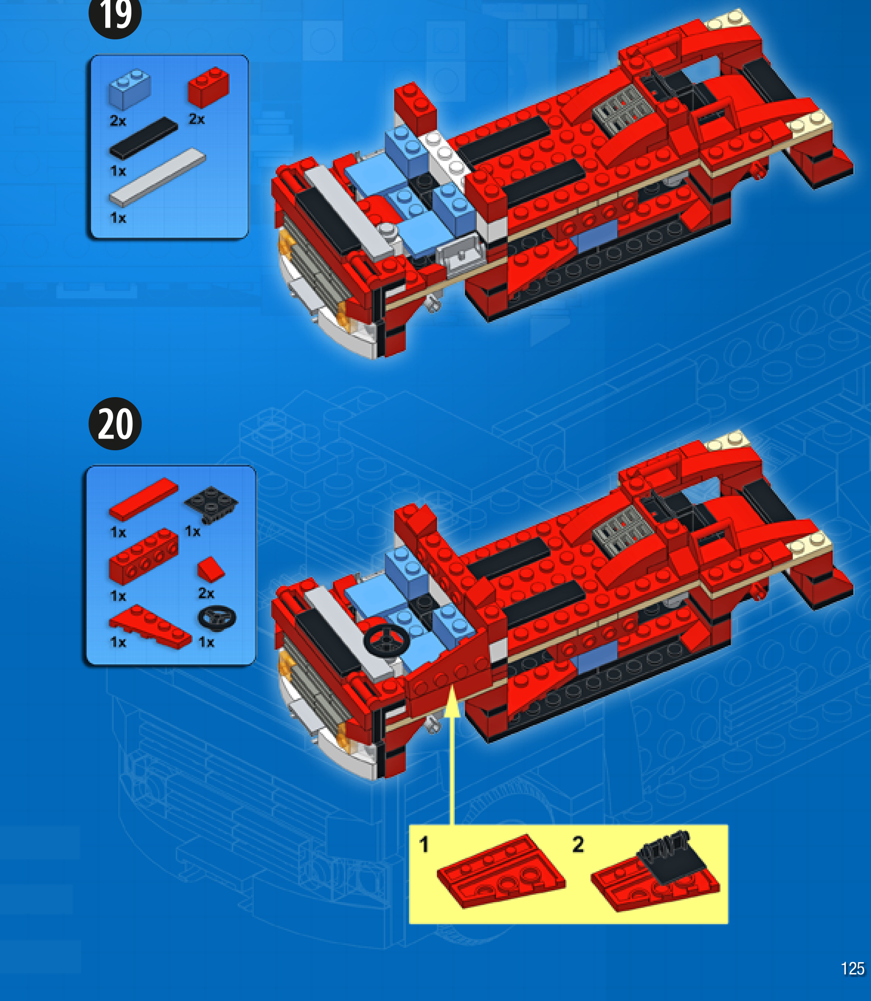
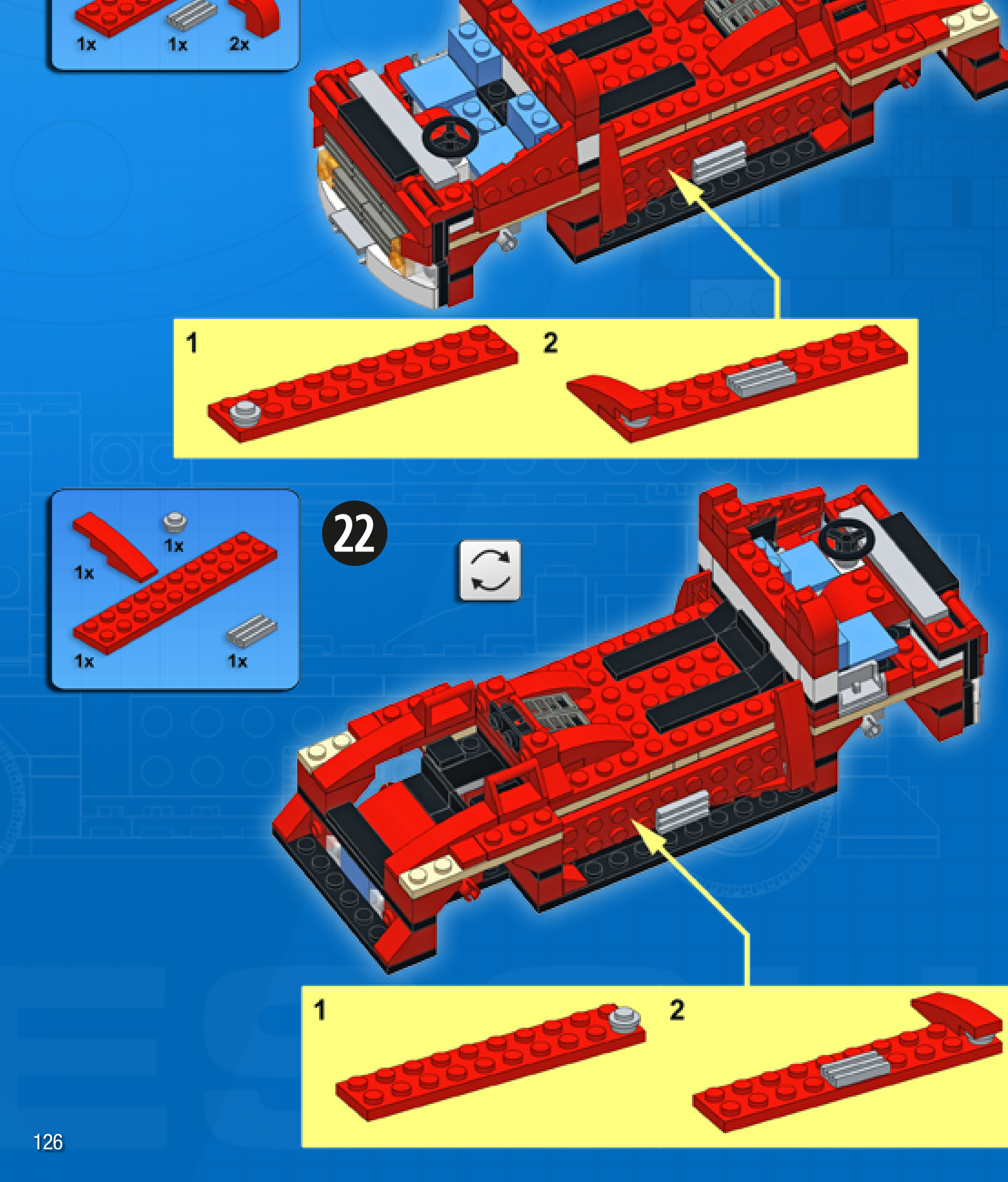
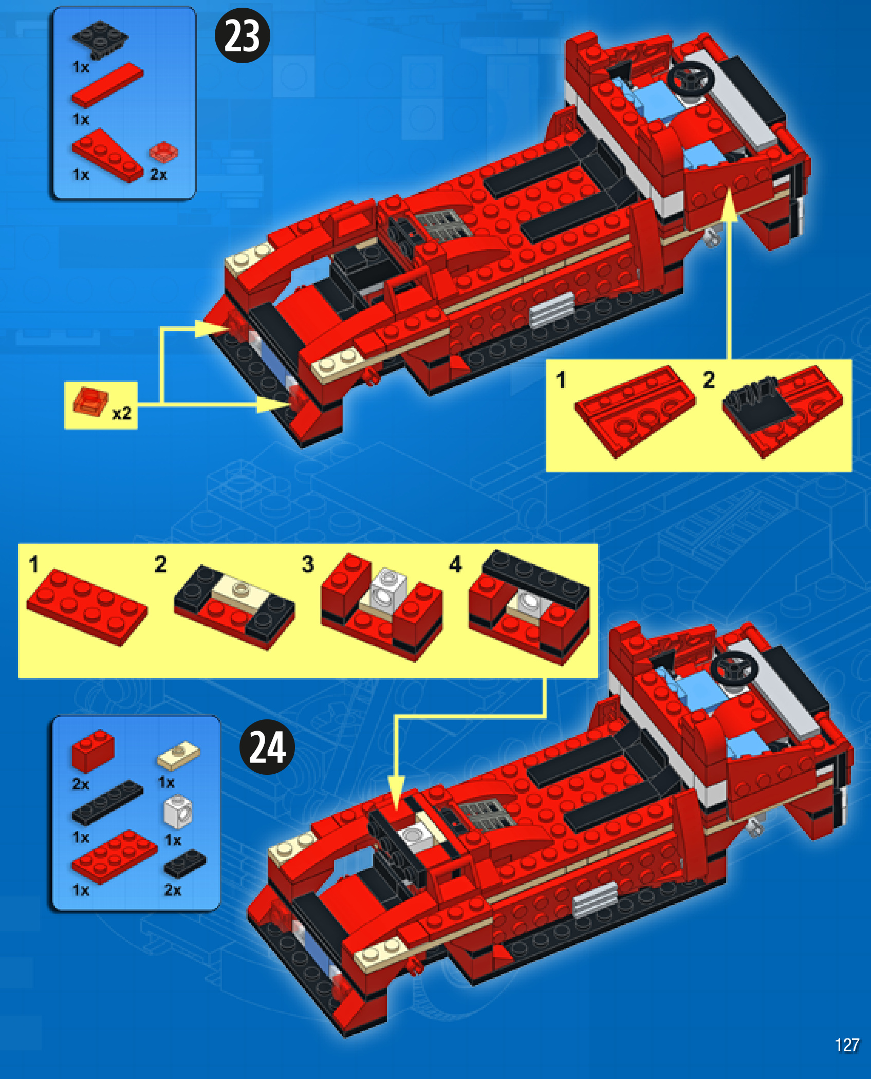
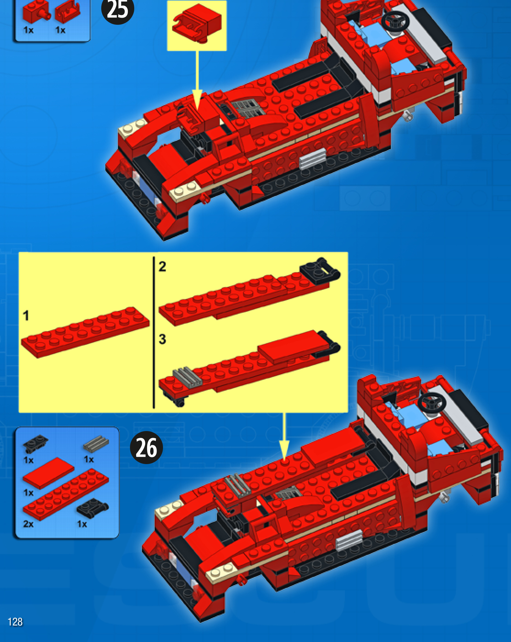

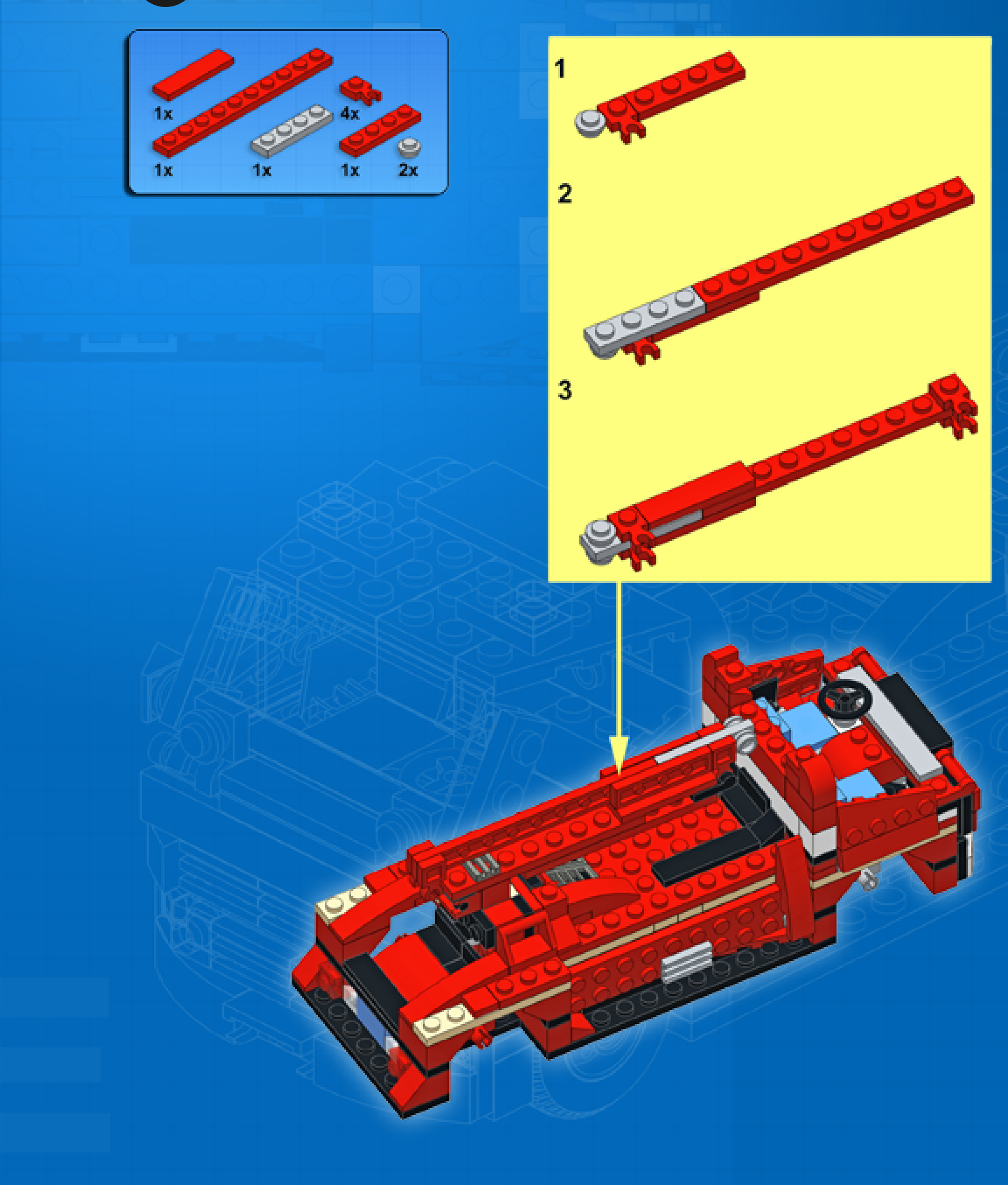
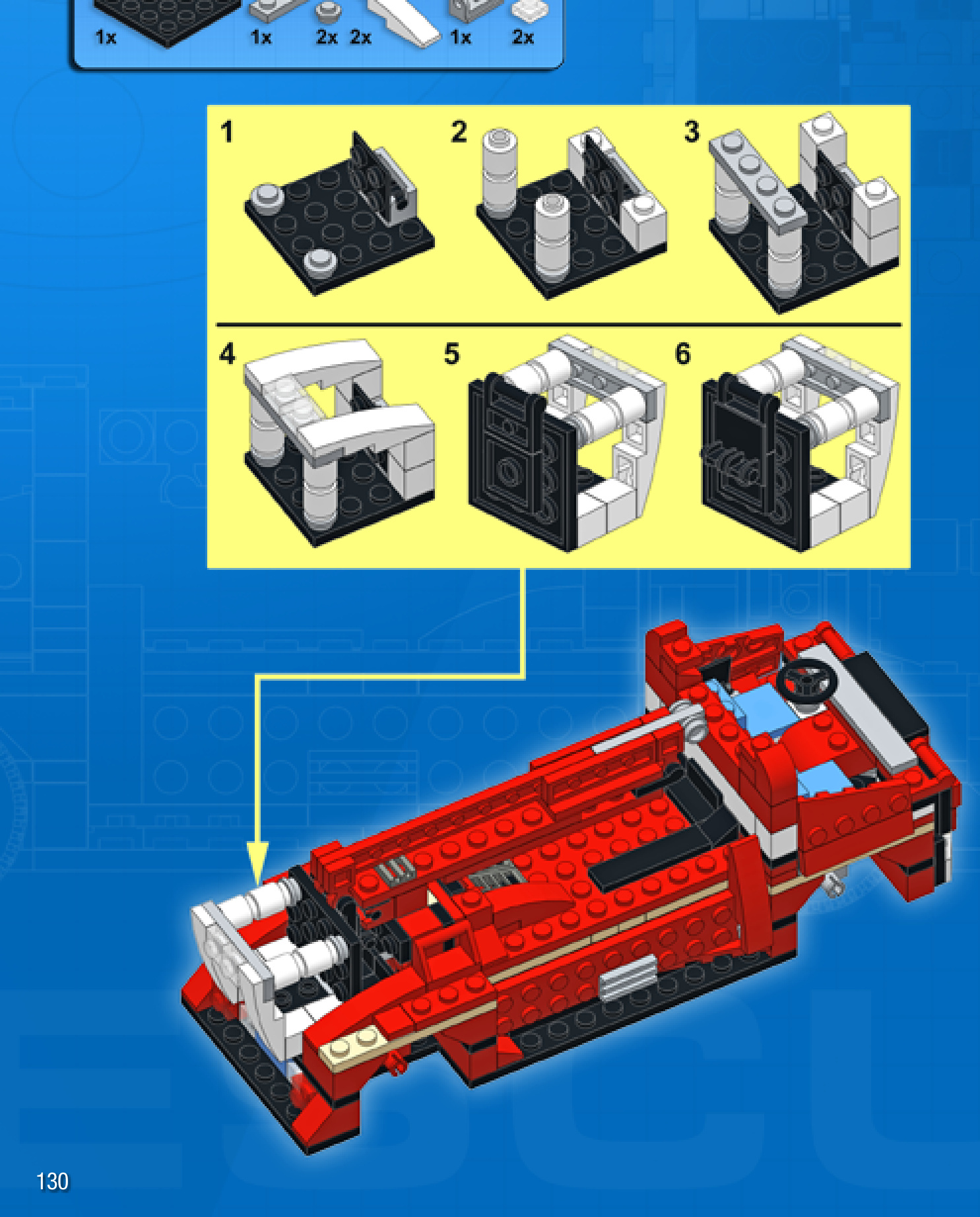
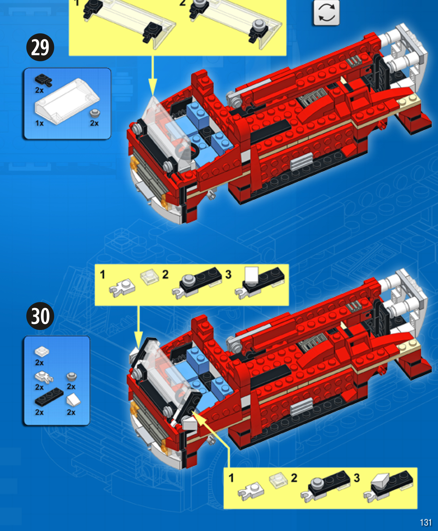
31