乐高建筑设计技巧
本书内容
本页包含乐高建筑的高级设计技巧,涵盖:
- 齿轮传动系统与组装技术
- 建筑颜色搭配与强调色运用
- 对称设计原则
- 设计流程与方法
- 现实世界到乐高零件的识别与转换
- 墙面、门窗、屋顶细节设计
- 柱子、栏杆、装饰细节
- 街道设施(报纸架、消防栓、停车计时器)
In Chapter 2, we looked at three basic methods for assembling bricks: stacking, staggering, and overlapping. On their own, these techniques might not seem very interesting, but you learned that they are critical skills that can be used in combination to help you build models as complex as you wish them to be.
Gear Trains
Figure 9-12 showcases two very important assembly techniques. The first is what’s known as a gear train.
Figure 9-12: In order from left to right, you see the driver, the idler, and the driven gear.
The example shown here consists of three gears and a small handle or crank on the opposite side of the beams. Turning the handle (as shown in Figure 9-13) has the effect of causing the first gear (on the left) to rotate. That forces the gear in the middle (also known as an idler gear in this scenario) to turn as well. Lastly, the idler gear passes on its rotation to the gear on the right (called the driven gear).
Figure 9-13: The gear set from the opposite side, showing the crank and also some full width bushing in action
The second technique demonstrated in Figure 9-12 is seen in the plates that hold the Technic bricks together.
Look at what happens in Figure 9-14 when I replace those plates with plates. It is easy then for the Technic bricks to shift out of alignment.
Figure 9-14: Looks can be deceiving. Although I only replaced the dark gray plates (both ends), the result is a major potential problem. See the next illustration to see what I mean.
Although at first things may not appear to be that bad, look at Figure 9-15 to see what can happen to the gears when the bricks become misaligned. It’s quickly obvious why the plates were so important. You’ll want to make sure you use or even wider plates when creating frameworks within which Technic axles will need to spin smoothly so that the Technic bricks remain perfectly parallel to each other.
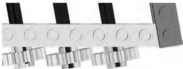
Figure 9-15: It takes only a minor misalignment to cause gears to no longer run smoothly. In the previous image, they appeared to be lined up, but in this top view, you can see that they clearly are not.
As you build any model containing Technic pieces, it’s very likely that you’ll spend at least some time making minor adjustments to the position of axles, pins, gears, and so on in order to make sure they line up as closely as possible.
Basics of Gear Ratios
If you’ve ever ridden a sleek 10-speed bicycle or a rugged mountain bike, you’ve probably already experienced the science of gear ratios. You know that when you are just getting the bike moving you want to be in a low gear. That is, you want to have a low ratio between the size of the chain ring in the front (attached to the pedals) and the cogs in the back (attached to the rear wheel). That means that you have to pedal a lot but that you have more power to get the bicycle in motion.
Then, as you gain speed, you know that the next step is to switch to a higher gear so that you are making fewer rotations of the pedals but getting much faster revolutions of the rear wheel. If you look down at this point, you see that the size of the chain ring you’re using in the front is much larger than the cog you’re using in the back. Take a look at some LEGO gears (in Figure 9-16) to see this further demonstrated.
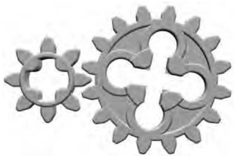
Figure 9-16: In this example, assume that the gear on the left is the driver and the one on the right is the driven gear. This demonstrates a low gear ratio that is slow but powerful.
Imagine that in Figure 9-16 the small gear (with 8 teeth) on the left is toward the front of the bike and the larger one (with 16 teeth) is on the wheel at the back.
NOTE I’ve left the chain out of this example to keep things as simple as possible.
The gear on the left is only one-half the size of the one on the right. That means that every time you rotate the small gear, the larger one moves only one-half of a circle. That is an example of a low gear, just like when you’re pulling away from the curb on your bike.
Switch gears, though, and you find that you’re now using a high gear ratio, like the example shown in Figure 9-17.
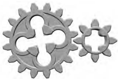
Figure 9-17: In this example, assume that the gear on the left is the driver and the one on the right is the driven gear. This demonstrates a high gear ratio that is fast but less powerful.
With the larger (driver) gear now at the front, the smaller (driven) gear has to move much more quickly to catch up. This is just like what you do on your bike once you are moving along at a reasonable speed. This means you have to do less work (turn the driver gear fewer times) in order to make the wheel (attached to the driven gear) move quickly.
Deciding which gear ratios to use (low and powerful or high and faster) depends upon what function the gears in your model are trying to accomplish
Going Vertical
Figure 9-18 showcases another classic Technic assembly trick. This one uses the inherent geometry of a standard Technic brick to allow one brick to be positioned perpendicular to the bricks around it.
The vertically aligned brick in Figure 9-18 may not, at first, appear to have much use. Keep in mind, though, that a piece like that may only set the stage for other more important pieces to be attached. Remember back in Chapter 3 I talked about alternative ways to assemble a roof? I showed you that with some standard plates and brick hinges you could create angled roofs that could take the place of slope elements. It’s possible, in certain situations, to do the same sort of substitution for walls as well. Figure 9-19 shows just such an example.
Although a bare plate, mounted with studs facing out, may not be exactly the look you’re after, you can use the piece as a base upon which to mount other elements, perhaps even a small mosaic or other decorative pieces.
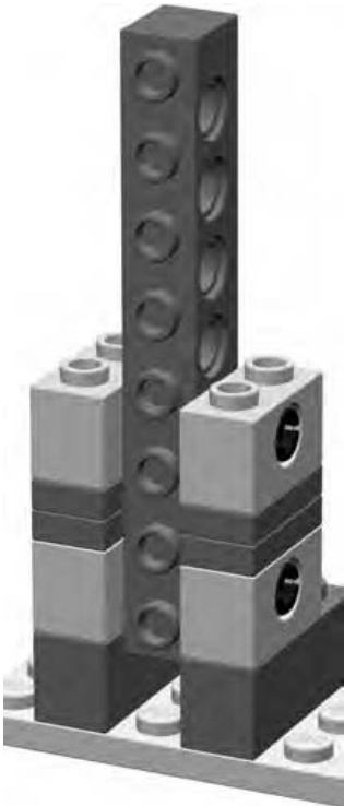
Figure 9-18: The pins shown peaking out of the Technic bricks are the key to holding the brick in its vertical position.
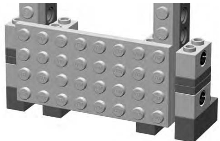
Figure 9-19: One example of a practical use for vertically positioned bricks. They can be used to mount large standard plates, which can then be used as walls or as mounting points for yet more elements.
Technic Meets Basic Elements
I’ve talked several times throughout this book about the built-in flexibility of the LEGO system. Adding Technic elements to the mix does not change this assessment. If anything, adding some Technic pieces to a model built primarily of regular system pieces only enhances the creative possibilities. Now you can have a car with working steering or a robot that has mechanical claws that open and close. A subtle variation on this theme is when Technic pieces are used to help system pieces interact in ways they wouldn’t otherwise be able to, but without turning the model into some sort of high-tech machine.
One interesting way to merge Technic and regular system parts is to use a group of pieces that I call pin-enabled pieces. (Figure 9-20 shows you a few samples.) You’ll find more of these in Appendix A of this book.
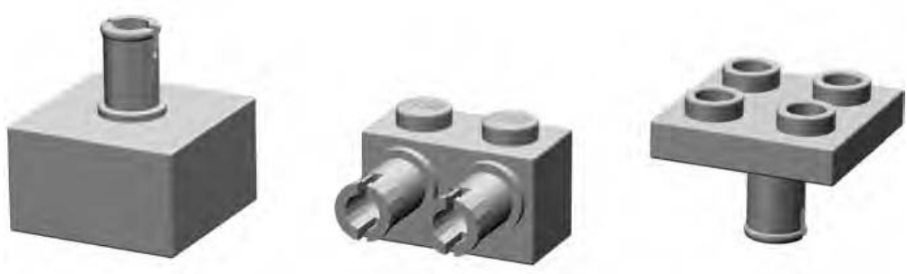
Figure 9-20: An assortment of various pin-enabled elements
These pieces are a subcategory of the specialized elements category. Each of these pieces is a hybrid of a standard system element and a Technic piece. This combination results in elements that have Technic-style pins attached to them in one way or another. You can then use these pins to connect to the holes found in Technic bricks, beams, and so on.
Now that you know what pin-enabled pieces are, how can you put them to use? There’s no one right answer to this question, so rather than try to list every possible scenario, I thought it might be best to just show you a simple example.
Back in Chapter 2 when I was discussing the stacking technique, I used a picture of an airplane tail to suggest a possible use for stacking bricks—to present different colored bricks as vertical stripes. Let’s borrow the airplane tail again for this section and imagine for a moment that it’s going to be part of a model that you want to take with you somewhere. Perhaps you’re joining some friends for a group display of LEGO models, or maybe the plane is traveling with you to visit relatives on the other side of the country. You know that the tail end of the model will look something like Figure 9-21.
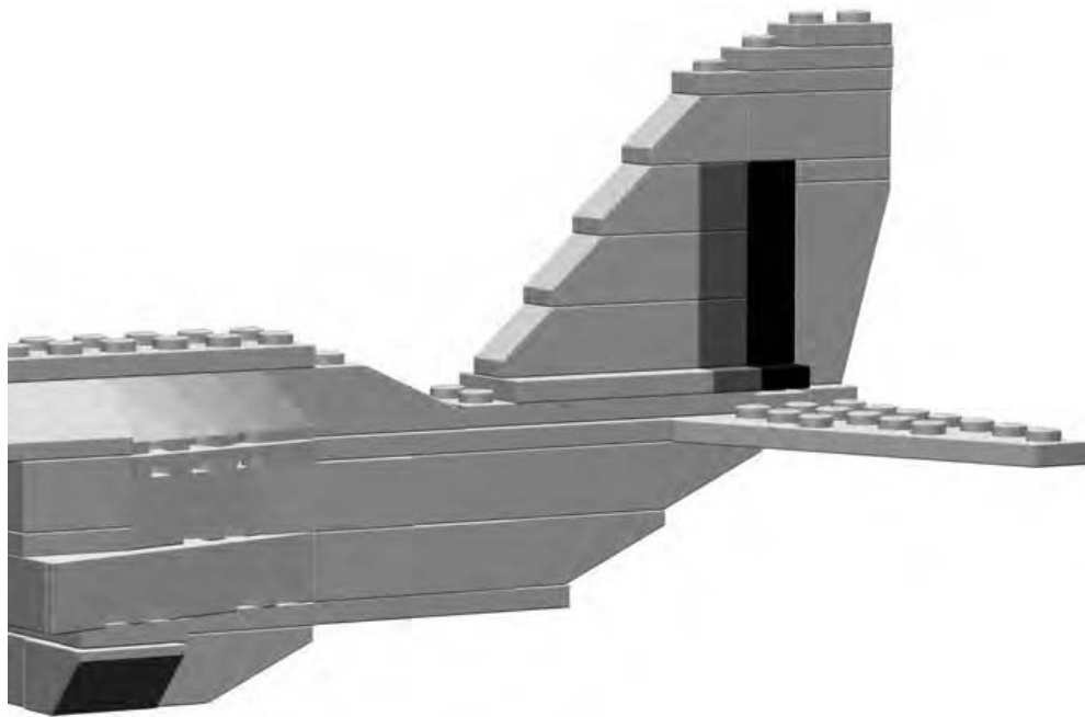
Figure 9-21: On the surface, this model may not look like it has any Technic pieces at all.
Regardless of where the model is going, you can envisage a scenario where you might want to remove the tail so that it does not get broken apart in transport. One simple way to do this is to build it as a submodel that you can remove from the body of the airplane. In Figure 9-22 you can see how this might be accomplished using pin-enabled elements and Technic pieces.
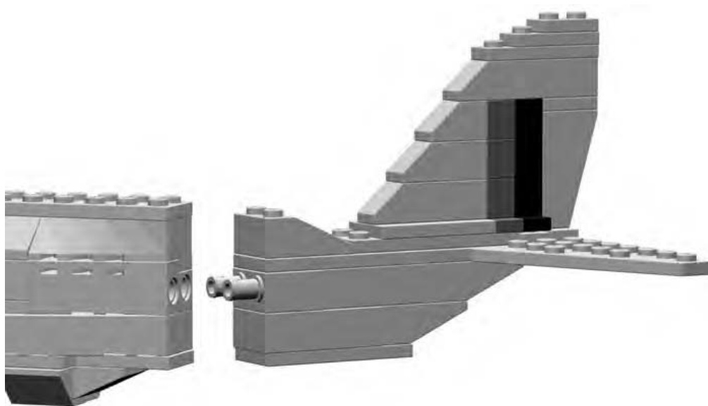
Figure 9-22: The tail can be easily removed so you can transport the model.
As demonstrated in Figure 9-22, you can remove the tail section as a complete unit from the rest of the airplane model. The close-up (in Figure 9-23) shows how each of the two key pieces is built into its respective section.
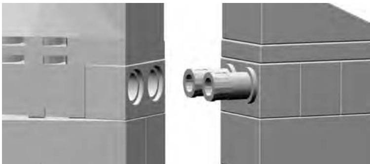
Figure 9-23: A close-up shows the secret hidden inside this model. A Technic brick lines up perfectly with a pin-enabled piece.
To accomplish this little trick, there are two things you want to keep in mind:
- Plan ahead and build the Technic bricks and pin-enabled elements into each of the two sections. Obviously you want to build them so that they align with each other. In the example of the plane tail, I’ve built the pieces into the center of the fuselage.
- Be sure that your sections end up as the same size and shape at the joint where the model and submodel meet up with each other. For the plane example, this means that when the tail is attached, it should look as though it is just a continuation of the rest of the aircraft.
Putting It All Together: Building a Technic Model
In the world of official LEGO sets, Technic models can sometimes rank among the largest and most complex designs. Some may be made up of 300 to 1,000 or more pieces. Some may have very few standard system parts in them, relying instead on large numbers of Technic bricks, beams, pins, and other parts I’ve talked about in this chapter. Your own Technic models need not be nearly this complex. You are, of course, free to incorporate as many or as few Technic pieces as you feel you need.
For the purposes of this book, in order to keep things a bit simpler, I’ve decided to present a Technic model that falls on the small side of the range. To illustrate how just a few Technic pieces can add interest and functions to an otherwise simple model, I designed the little helicopter you see in Figure 9-24.
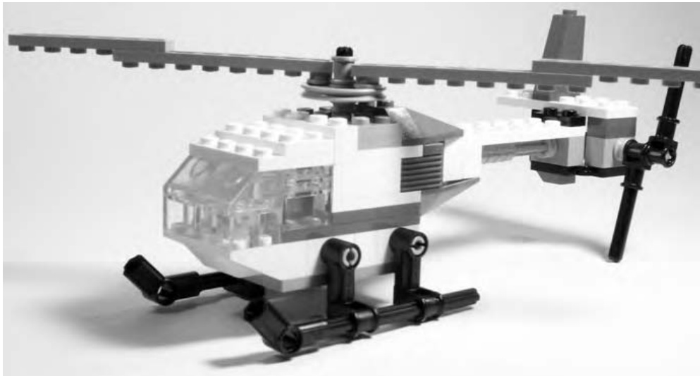
Figure 9-24: Technic models don’t have to be enormous or enormously complicated to be interesting.
At first glance, you might look at Figure 9-24 and wonder, “What makes this a Technic model?” That’s a question worth asking, so let’s take a closer look.
Right off the bat, a couple of things are obvious, and one thing might not be so obvious. If you look at the helicopter, it’s easy to see that the landing gear and tail rotor are both made completely from what we’ve already identified as Technic pieces in this chapter. The landing gear (as seen in Figure 9-24) is made up of coupler elements and axles, attached to keyhole bricks that make up part of the helicopter’s body.
Although the tail section may seem a bit oversized for the rest of the model, it is not without reason. Hidden behind the two Technic bricks are two bevel gears. You can see them in Figure 9-25, which is taken from the rear of the model.
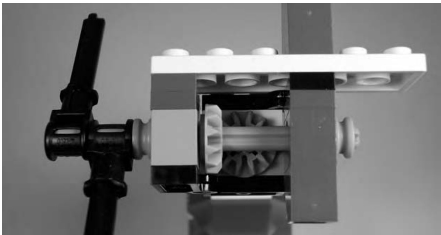
Figure 9-25: Two bevel gears meet at a right angle. This transfers motion from one axle to the other. Note the half-width bushing on the right, holding the axle in place.
You can see that the first of the two gears is mounted on the same axle as the tail rotor pieces (also made from Technic elements). That gear, in turn, mates with a second identical piece that attaches to the drive shaft that runs the length of the helicopter’s tail. The shaft itself is much more visible in Figure 9-26.
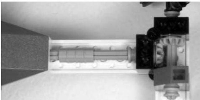
Figure 9-26: This shot might be disorienting at first. You’re looking at the underside of the tail; the main body of the copter is at the left. This shows how the motion is transferred from the tail through to the main rotor.
The shaft then continues into the body of the copter where it ends in yet another bevel gear. This time the gear transfers its motion to a similar piece mounted vertically on the shaft connected to the main propellers. You can see both the gear inside the body and the one that drives the propellers in Figure 9-27.
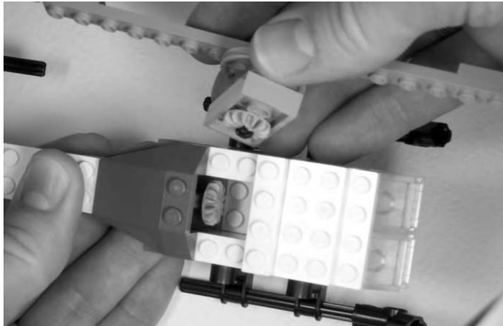
Figure 9-27: You can think of the rotor, including its bevel gear, as a subassembly, and you can build it separately from the model so it can be added last.
When fully assembled, the two bevel gears (inside the body of the helicopter) mate perfectly. If you’ve been following along, you’ll know how the whole thing comes together. The small tail rotor acts like a handle that you can crank. The motion you put into the tail rotor is transferred along the main drive shaft into the helicopter body and then passed along again to the main rotor.
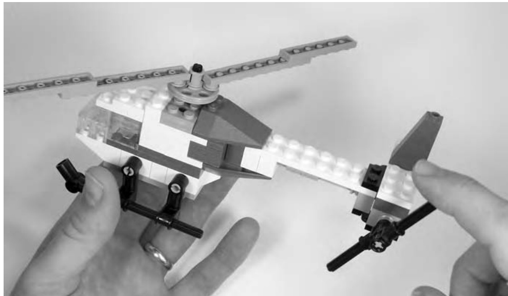
Figure 9-28: The still image shown here doesn’t show the action that occurs when the tail rotor is moved. When you build your own, you’ll see that.
The result, as demonstrated in Figure 9-28, is that by turning the tail, you cause the larger propellers to rotate. Any movement of the small tail rotor causes the larger blades to spin, and it is this special function that earns this little model the Technic moniker. This is a simple, yet effective, demonstration of a model that, without Technic pieces, would be far less interesting.
NOTE Complete instructions for the helicopter example are included on the website that accompanies this book. Go to www.apotome.com/instructions.html to download full color steps to build your own version of this little model.
Review: What Is Technic?
In this chapter, we sought to answer one simple question, “What is Technic?” You discovered that the answer really has two parts to it. First, you found out that Technic is a system within a system. It is a set of LEGO elements with unique and interesting features that can also work with the standard parts you’ve seen elsewhere in this book. Second, you saw that Technic is also a style of building with the specialized pieces that make up this class of parts. This could mean wheeled vehicles that have working steering or it could mean a small helicopter with rotor blades that turn when you give its tail a spin with your finger.
Defining Technic wasn’t as easy as some of the other questions we’ve tackled in this text, but you shouldn’t feel that Technic-style models are beyond your reach in terms of part selection or skills required. As you saw with the helicopter example, a Technic model doesn’t need thousands of parts to make it interesting. It only needs one clever function that makes use of one or more Technic pieces. That’s what makes it different than a model made from only standard system parts. And that’s all you need to know to answer the question, “What is Technic?”
10
P U T T I N G I T A L L T O G E T H E R : W H E R E I D E A S M E E T B R I C K S
We’ve covered a lot of topics up to this point. Throughout the various chapters, you’ve looked at basic building techniques, like overlapping and stacking; you’ve looked at different types of LEGO elements and how best to use them; and you’ve looked at ideas, like scale and color. Now it’s time to put those skills to use. This chapter focuses on you, the builder, working toward designing the models you want to make. So, print out some Design Grids (see Appendix B), dump some bricks out onto your building table, and get to work!
Thinking Like a Model Designer
The role of designer is one you take on the minute you step away from existing sets and instructions for building LEGO models. Whether you are working from a real life inspiration or creating something from your imagination— something that has never existed before—you are designing the model of what will be the final result. Part of the joy of LEGO elements is that they allow nearly limitless combinations and patterns. Therefore you, as the designer, have hardly any boundaries.
If you are like some people, you may find the sense of being in complete control overwhelming. Although your head may be full of ideas, it may seem daunting to try and figure out how to turn those ideas into actual models. You may end up with a sketchpad that looks like Figure 10-1.
Figure 10-1: Freedom to create anything imaginable can leave some people wondering what to build.
Sometimes knowing what to leave out of your project makes as much difference as what you put in. That’s where this chapter comes in.
Limit Your Scope
The term scope refers to the range of facets that your model is designed to encompass. In other words, scope seeks to help you answer these questions: “What is the purpose of this design?” and “How will I accomplish it?” It’s quite easy to sit down at your build table with bricks at the ready and announce, “I’m going to build the Empire State Building!” You can then decide that this model will be 20 feet tall, include hundreds of windows, and be made entirely from light gray bricks. Such a model is possible. But is it out of your league right now? Probably so. Most likely, you’ve given it a scope that is far too large for you to accomplish at this time.
So, let’s try again.
After you decide you want to build the Empire State Building, you look at your bricks and discover that you have a good number of dark gray, light gray, and white bricks. Why not use these colors to build your model? Perhaps changing colors at different layers of the building where the width or shape changes will help you make the shift look more natural. You also find that your supply of transparent bricks and/or windows is severely limited, so re-creating each window is out of scope and beyond your limits. Instead, you decide to use black bricks to simulate window openings. Lastly, you decide that a 2-or 3-foot-tall structure is probably more realistic than a 20-foot-tall one given the number of bricks in your collection.
You have just laid down a scope for your project that is much more feasible than your initial desires. Finding a suitable goal for building is not meant to be a limiting factor; rather, it’s a guide that can help you be more successful in your endeavor and ultimately more satisfied with the time and effort you put into building.
Part of limiting your scope involves knowing what to leave out. In the Empire State Building example, one thing you left out was height. You reduced it to something more realistic. Quite simply, the idea for the first model was too big for the average builder. Second, you substituted a part for a specific detail on the real building that would have been difficult to accomplish otherwise. This was your black-bricks-for-windows solution.
You also decided to mix some colors so you could still build a reasonably tall model that didn’t break the bank when it came to the number of bricks you needed in any single color. For most builders, the need to use more than one color (regardless of the actual color of the object being modeled) is a constant reality. As with size, though, your color limitations do not need to limit your creativity. Simply look at what you have and adjust your scope accordingly. For the Empire State Building example, the idea that your colors will include different grays, white, and black means that it might, in fact, be as visually interesting as if you had built it entirely in a single color. In this case, you might consider adding colors as a way to increase the scope, but it’s actually adding clarity to the goal and materials you need to accomplish your model.
Having a well-defined scope also helps you decide the level of detail that you want to include. Ask yourself a question like this: “Am I striving for a high degree of realism in this model?” If you’re doing a life-sized sculpture of a pet cat, then this is very possible. If you’re doing a 3-foot-tall Empire State Building, the answer is quite different. You are forced to drop certain details to build to the reduced height you have chosen. Intricate detailing above windows may have to go, and you may have to represent the feeling of where windows would be, not each and every window. In addition, you might have to settle for simplified doors and other street-level accoutrements.
Learning to build within these types of boundaries is not as restrictive as it might first sound. In fact, it’s an excellent way to improve your skills, hone your artistic eye, and maximize the enjoyment you get from your existing collection of LEGO bricks.
Getting Started: Pick Your Subject
Let’s pick a subject for a model and follow it through from the first step to the last piece you need to complete it. Building with LEGO bricks is no at all fun if you don’t like the subject matter you’re working with. For that reason, be sure that you pick things to model that have some interest to you. Because you’re just beginning to design your own models, you may want to pick subjects that challenge you on different levels. Pick tall thin models (like the Empire State Building) to practice your column building techniques. Choose realistic buildings (like a minifig-scale restaurant) to work on building to an exact scale.
In order to illustrate as many of the design and building principles as possible, I’m going to have you try to create your own original model of the NASA Space Shuttle. The reason for picking this subject is that it should offer a good mix of shape, color, and construction challenges.
Because this is an original model, why not give it an original name? The name Triton is appropriate for two reasons. First, it is the name of a real ship that once sailed as part of the British Royal Navy. Second, it is still the name of the largest moon that circles the planet Neptune. This model, then, is a fictional version of a real ship. That’s okay because it adds some personal character to the original model. Figure 10-2 shows what Triton will look like when you’re done designing and building it.
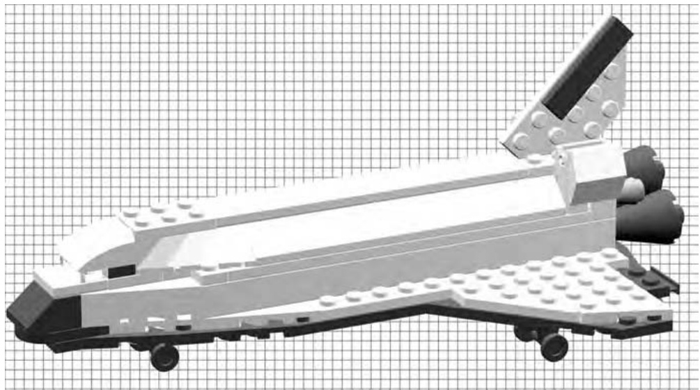
Figure 10-2: This is the goal of the design exercise.
While you’re at it, why not give this project a set number? Because it’s the first you’re building using the techniques in this book, how about calling it set . (It’s not really necessary to give your models set numbers, but for the sake of this exercise, it adds a sense of authenticity.)
Of course, you won’t have a picture of a finished model to work from, but you can gather pictures to help inspire you. Photos from books, the Internet, or even ones you might have taken yourself can all help give you ideas to work with.
Work from the Bottom Up
Where do you start when you want to build something like the shuttle? What section do you build first? You could start with the tail section, but if you did, how would you know if it is going to be the right size? You could begin constructing the cargo bay doors, but would you be able to easily attach them once the rest of the shuttle was done?
Rather than starting with either of those options, first look at what you’re trying to duplicate. The shuttle has many distinctive features, but one stands out above all of the others: its unique wing design (as you can see in the drawing I’ve made in Figure 10-3 using Design Grid #1).
Because the wings are effectively the bottom of the shuttle, they are an excellent place to start modeling. This answers the question of what section you are going to build first. You can then decide how to attach and accurately scale other parts of the ship to match the wings. This is not unlike creating the ground floor of a building first so you know how wide and tall the remaining floors should be.
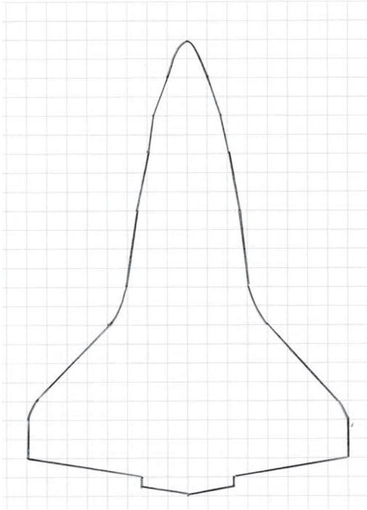
Figure 10-3: Copying the outline from a photo or drawing can help you achieve realistic results.
I created the outline you see in Figure 10-3 using the following very simple steps:
- I searched the Internet until I found a diagram that showed the shape of the shuttle wings from below.
- I printed this image onto a sheet of plain paper.
- I printed out a copy of Design Grid #1 from Appendix B. This is the grid that gives you a top-down look at a model, as though you were seeing it from above looking down at the studs.
- Finally, I put the image from the Internet under the Design Grid and traced the outline of the wings. This gave me a very accurate reproduction of the shape and a blueprint to help me find LEGO pieces that could match that outline.
The shuttle wings are far from the basic rectangles that formed the shape of the Wright brothers’ flyer back at the beginning of the twentieth century. Therefore, to re-create their shape, you need parts that are more tapered. Wing plates and diamond-cut plates (see the Brickopedia, Appendix A, for sizes and shapes) should provide you with the geometric shapes you need.
Creating the wing using the Design Grid is just like putting together a jigsaw puzzle, except that instead of being given the pieces to assemble, you must find suitable pieces in your collection and get them to match the outline you’ve drawn on the grid.
You’ll notice that in Figure 10-4, I used wing plates to form the outer shape but then standard plates for the space between. You can literally set real pieces on top of your penciled-in design because the squares on the Design Grid are exactly one stud by one stud in size.
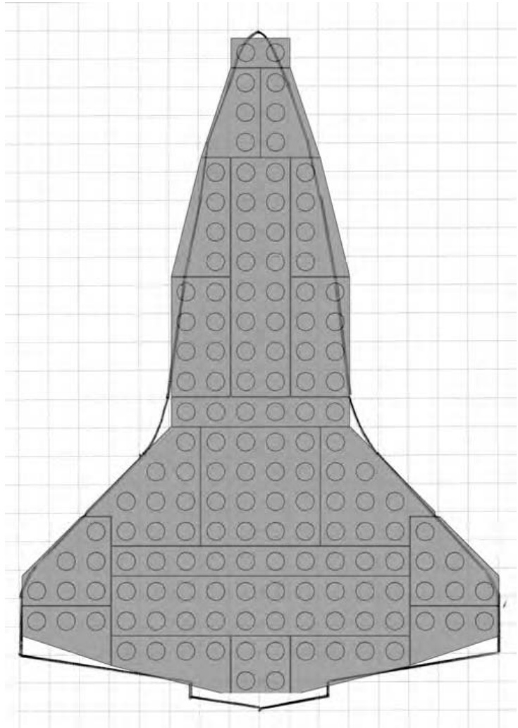
Figure 10-4: The LEGO elements are superimposed on a copy of the Design Grid with the outline of the wings drawn in.
Together these elements give you the foundation upon which to build the rest of the vehicle.
The size and quantity of these plates might vary if you are designing this model based on your own collection of parts. For instance, you might have to substitute standard plates in some cases where you don’t have the exact wing plates I used here. But the goal always remains the same: regardless of whether your shuttle is 10 studs long or 100 studs long, you still want to try and make it look like the real thing.
Let Reality Guide Your Design Decisions
The idea illustrated earlier—finding one feature of an object upon which to base your model—is one that you can apply to nearly every creation you take from real life inspiration. It’s as simply as following these three steps:
- Take a distinctive feature from the item being modeled. In the shuttle example, you are using the unique wing as your guide. For a model of a train engine, you might select the crew cab. For a spaceship, you might decide upon the engines as your starting place. In all cases, you want to find something interesting you can use as a guide.
- Decide upon the types of elements that are best suited to represent that feature. In the shuttle example, you pick out wing plates that help you match the shape, drawn on the Design Grids, based on the real wings. You don’t pay much attention to size so much as you focus on duplicating the angles.
- Build the rest of the model by incorporating other elements that work with those in step 2. As you finish the shuttle example, you’ll see that the choices for each of the other sections, including the bricks used to make them, are driven by the base you set down in step 2. The wings provide a fixed reference upon which you build, both literally and figuratively, the rest of the model.
These steps provide you with a basic wing design, but right away you need to make a structural decision. How will you hold all these pieces together? Perhaps the easiest way to solve this dilemma is to follow the guide provided by the actual shuttle.
The portion of the wings you’ve created so far is most like the protective tiles that cover the underside of the ship. When you look at the real shuttle, you see that the upper layer of the wings is almost the same size and shape, but it is made from a different material than the tiles underneath. You can duplicate that look by adding a second layer of plates in a different color. As you can see in Figure 10-5, the second layer does not exactly match the shape of the first, but that’s all part of the design. By working to re-create the parts seen on the actual shuttle, you end up solving the problem of holding your first layer of plates together.
If the second layer of plates was configured exactly the same as the first layer, nothing would hold them together. By selecting different sizes and shapes of plates, you make sure that the individual parts are arranged to take the best advantage of the overlap technique.
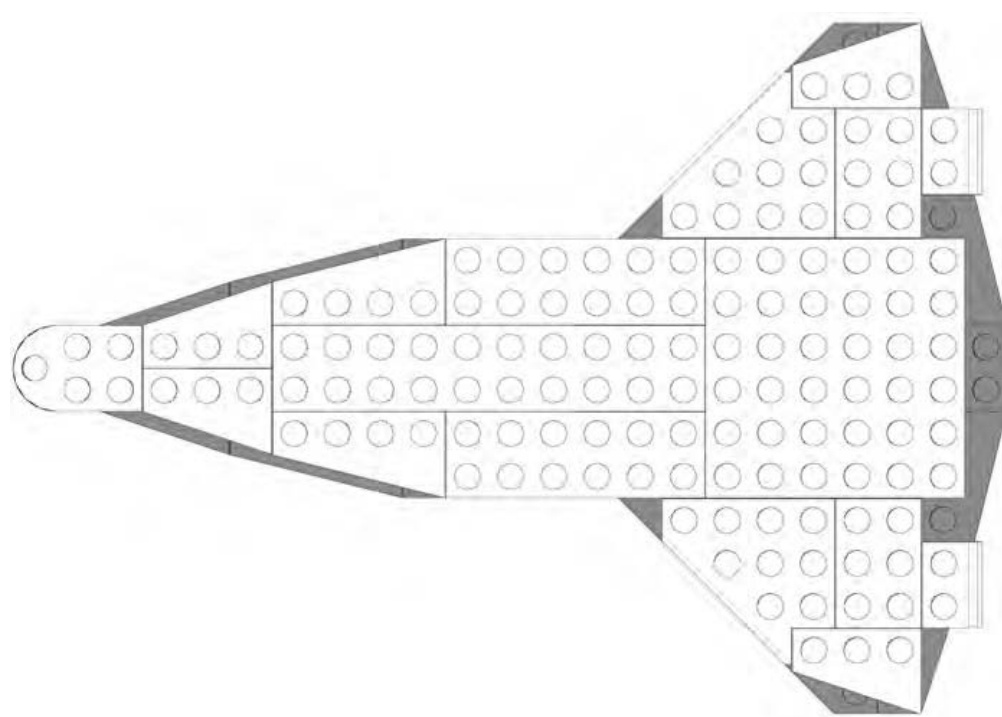
Figure 10-5: The second layer of plates doesn’t quite match the first, but that’s the way you want it.
A Different Perspective
So far, in this example, you’ve been using only Design Grid #1 from Appendix B. This grid looks down on a model from above, showing you only the tops of the bricks. It’s good for estimating the length and width of the model as well as its overall shape, however, it does not allow you to see the height. That’s why at this point, you want to begin using Design Grid #3 or #4 (Appendix B); they show a model from the side.
Each small rectangle on these grids represents a plate as seen from the side. You can use this perspective to decide how many layers of bricks or plates you need to achieve your goal. You saw how you could apply this technique to planning a model back in Chapter 6 when you used the same grid to help plan the Empire State Building micro model. In that case, you used the portrait version (Design Grid #3) of the plate-view Design Grid. For the shuttle design work, you will use the landscape version (Design Grid #4) of the side-view grid. Because this sheet is longer than it is tall, it will accommodate a sketch of the shuttle as seen from the side.
NOTE See Appendix B for more information on how best to use the Design Grids.
As you can see in Figure 10-6, by using the side-view grid paper, you can plan how tall the model will be (in this case, the body is roughly 3 bricks high) and also determine the location of key structures like the tail and engines.
Figure 10-6: Sketches don’t have to be perfect to be useful.
As you draw your plan, don’t worry about making your sketch fit the lines on the Design Grids exactly. You will inevitably end up making compromises between what you draw and what you actually build. Rather than being a bad thing, compromise is often where the most inspired ideas come from. Sometimes not having what you think is the right piece leads you to using another piece (or pieces) that actually ends up providing a better solution.
Pick a Scale, Any Scale
Choosing a scale for any original model is one of the key decisions you’ll make. We’ve talked about scale a number of times already in this book, especially in Chapters 3, 5, and 6. In the case of your shuttle model, you’ve let the design of the wing, and how it matches available wing plates, set the scale for you. In other cases, you might decide to pick a scale in advance and build everything to that exact size. The train station we built in Chapter 3 is an example of that style of design. The point here is that, since this is an original model, you have complete control over the scale you chose. If you’re trying to match the size of another model for any reason, then you need to work to that scale. Otherwise, it’s whatever scale you feel is best for the particular project you’re working on.
Color Concerns
Like scale selection, selecting colors for your models is entirely up to you. And like scale, you may also have specific reasons for choosing one set of colors over another, based on what feeling you want your model to project. Color can change the way that people react to or feel about a model. For instance, a sculpture of a dog made out of blue bricks might make people think of a cartoon character rather than a real pet. A building made out of mostly gray bricks might make the structure feel more like a warehouse or a factory than a comfortable home.
Apart from the way a single color can affect the impression the model makes, combinations of colors can also have a dramatic effect on how people react to your work. For example, a helicopter built from primarily white bricks with red accent pieces will probably make most people think of an air ambulance. If you use the exact same design except you build it from black or dark gray bricks, you might lead people to think it is a military or police vehicle.
It’s the fact that people have become accustomed to certain color combinations that makes them think of particular themes or settings. A model built of black and yellow bricks might give the feeling that it is somehow related to construction or industrial use because those are often colors used in those settings. Rides you find in amusement parks are often painted in bright primary colors like red, yellow, and blue. This gives them a feeling of fun that matches their purpose. The various color combinations go on and on. As you design your model, remember to look at the colors you are using to see if they represent the theme or the feeling you are trying to convey.
In the case of the shuttle model, you can let reality guide you. The real shuttle uses almost exclusively white and black pieces, reminiscent of the standard NASA color scheme for many of its rocket programs over the years. By sticking to the colors that people expect for the shuttle, you help add realism to your model despite its small size. As you can see in Figure 10-7, the black and white bricks create a dramatic contrast that brings out some of the main features on the ship.
Figure 10-7: The contrasting black-and-white color scheme adds realism to your mini shuttle.
Elements of Design
There are certain ideas you need to keep in mind no matter what type of model you’re planning to build. Although art courses may go into greater detail, this text focuses on only four major concepts of design theory: shape, color, proportion, and repetition.
Shape
What shape will your model be? There is a reason a car isn’t shaped like a tree. Think about what form you are trying to create. For example, a plain
flat wall can be boring. Don’t forget to include curves, angles, indents, and other interesting surfaces in your model.
How shape relates to the shuttle model
In the case of the shuttle, you were trying to re-create the shape of the original ship (see Figure 10-8). This is one of your most important goals when you’re working from a real life inspiration. Try your best to find the pieces in your collection that most accurately represent the shapes you are copying from the real object. In Figure 10-8, you can see that I selected certain plates for the wings and slopes for the top of the body, since those helped the most to re-create the shapes I wanted.
Figure 10-8: The shape of the shuttle is very distinctive, so matching that in your model is critical.
Color
Are you going to work with a couple of colors, or will you dig through your collection in order to use all the colors of the rainbow? Your choice of color can affect the overall impression the model makes, especially when combined with the shape(s) you have used.
How color relates to the shuttle model
Once again, you are led by reality when you select colors for the shuttle model. Black, white, and shades of gray are the most appropriate (see Figure 10-9). However, if you want to have some fun, you can build the same model in different color schemes. Perhaps a black and yellow version could be a construction shuttle, destined for a space station. Or, a red and white version could be a rescue shuttle, standing by in case of an emergency.
Figure 10-9: Wings made from black and white plates and differences in the colors of the engines help bring some details out on this otherwise monochromatic model.
Proportion
Are the substructures of the model the right size for each other? In other words, are they all the same scale? For example, building the doors to the same scale as the windows makes a building look more realistic.
How proportion relates to the shuttle model
The real shuttle is a complex flying machine. To make it so your model emulates this, you need to retain the correct balance between the length of the body and the width of the wings. You have to make sure the tail (shown in Figure 10-10) is tall enough, but not too tall and not too thick. You need to design the wings so that they are strong enough to serve as the base of the model but still thin enough to look like they are able to fly.
Figure 10-10: A single plate—mounted vertically between the studs below—offers the best solution to a tail that is tall and thin.
Repetition
Rows and rows of bricks are boring. But a few rows of arches can be beautiful. Sometimes including the same shape over and over can add dimension to your model. Just be sure you select an interesting shape or LEGO element before you add too many to your creation.
How repetition relates to the shuttle model
The shuttle model uses repetition to good effect by employing tiles (shown in Figure 10-11) along the top of the cargo bay doors, giving at least the impression that they might open. In fact, the doors themselves, made from 45-degree slopes, are also an example of where repetition can help add authenticity to a model.
Figure 10-11: On this small model, you only repeated a few tiles and slopes to make the cargo bay doors. On a larger scale version of the shuttle, you will find yourself using much more repetition.
Bringing It All Together: The Final Design
I’ve talked about many aspects of design theory and how they apply to the model of the fictional Space Shuttle Triton. It’s now time for you to become familiar with the instructions for building this creation.
I’ve included these instructions, along with build notes for each step. In Figure 10-12, you’ll find the list of the pieces you need to make this model. As always, don’t forget that substitution is a regular part of the building process when you’re making original models. If you don’t have every piece shown in the Bill of Materials, try to find a part or several parts that you can substitute for what is shown.
Figure 10-12: Bill of Materials for the shuttle Triton model
Step by Step: Shuttle Construction Details
As with many of the models featured in this book, I built a version of the shuttle using computer software. This allowed me to mark each building step as I went along so that the program could then create an image for each stage of the construction. I use a program called LeoCAD, but other such programs are available.
NOTE For a complete list of software you can use to design LEGO models on your computer, visit my website: www.apotome.com/links.html.
Step 1
Figure 10-13 shows you something similar to what you saw in Figure 10-4 earlier in the chapter.
Figure 10-13: A combination of plates creates the unique shuttle wing shape.
This is the bottom layer of the wing structure. Look for a place within each model you design that makes sense as a starting point. In the case of the shuttle, the wings serve as an excellent base upon which to build the remainder of the craft.
Step 2
The second layer of plates (as seen in Figure 10-14) are close to following the outline of the lower layer, but they do not match it exactly. This slight mismatch is the result of a conscious design decision. If you look at the real shuttle’s wings, you’ll see some of the protective heat absorbing material lining the front edges. By leaving some of the lower layer exposed, you create the illusion of that material on the model. This is a slight variation on the staggering technique you first saw back in Chapter 2.
Figure 10-14: The second layer of plates helps hold the first layer together.
Step 3
The body of the shuttle model is very simple. At this scale, there isn’t room for as much detail as perhaps you’d like. As you see in Figure 10-15, you’ve just concentrated on trying to create the basic outline for the cargo bay.
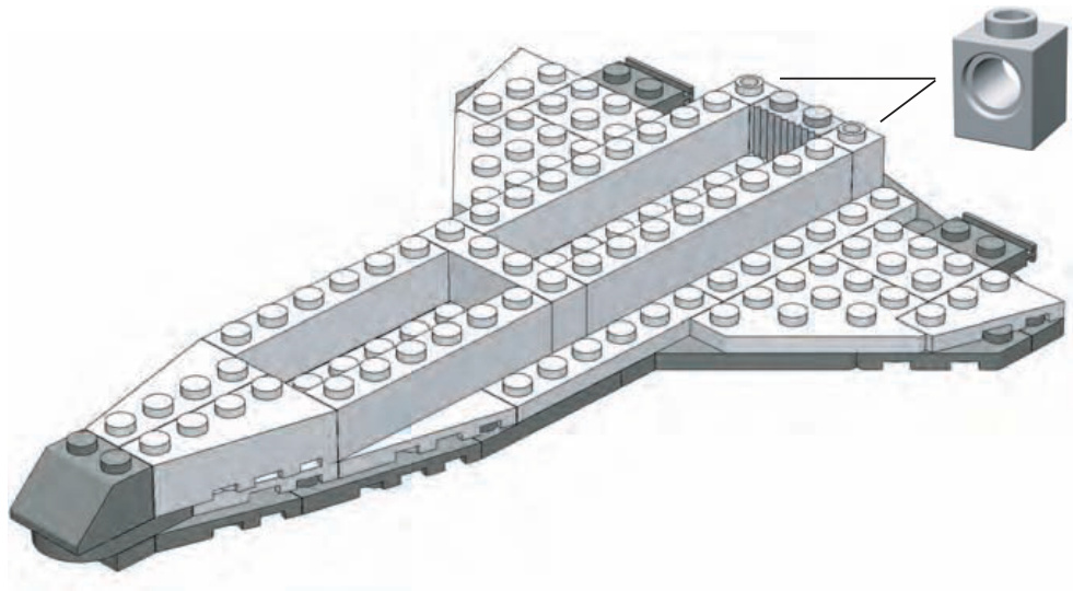
Figure 10-15: The inserted image in the top right corner gives you a building hint, since it’s hard to see just what pieces should go at the end of the craft. In this case, it’s two Technic bricks that go on either side of the grille brick.
The brick across the middle helps support the plates that you’ll add in the next step. You need to make similar decisions about detail when you create your own models. Don’t be afraid to design as realistically as possible, but don’t overwhelm a small model with more details than it can handle.
Ultimately you need to ask yourself, “Does this model look like what I want it to look like?” As long as the answer is yes, then you’ve got a successful design.
Step 4
Because this model is for display purposes and isn’t meant to be functional, creating a hollow cargo bay isn’t important to the success of the design. Instead, use plates (see Figure 10-16) to join the side walls together.
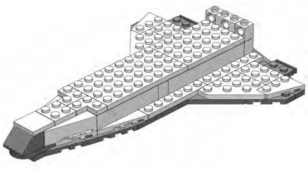
Figure 10-16: More Technic bricks near the back of the body. This time it is obvious which pieces to use, so no insert is necessary.
This gives you a ship that is sturdier and holds up better to being whooshed about the room. A larger-scale model of the shuttle might have included such things as retractable landing gear or movable wing flaps. But it might have been difficult to try to make them work on the small scale you’re working with here. You need to decide how many details to include or leave out based on the size of your project.
Step 5
The shuttle model that you’re building is really fairly small, so it comes together quite quickly. In Figure 10-17, you can see that, by step 5, you’re already adding the 45-degree slopes that form the cargo bay doors.
Although it’s hard to distinguish in these black-and-white instructions, the plate nearest to the nose of the ship is a transparent element. Remember, the doors aren’t functional—they are only for show. But at this scale, such a design decision is acceptable as long as it fits with the look and feel of the rest of the model.
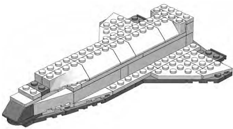
Figure 10-17: The cargo bay doors are already in place.
Step 6
You can sometimes add several unrelated portions of the model all in the same step. Figure 10-18 shows an example of this.
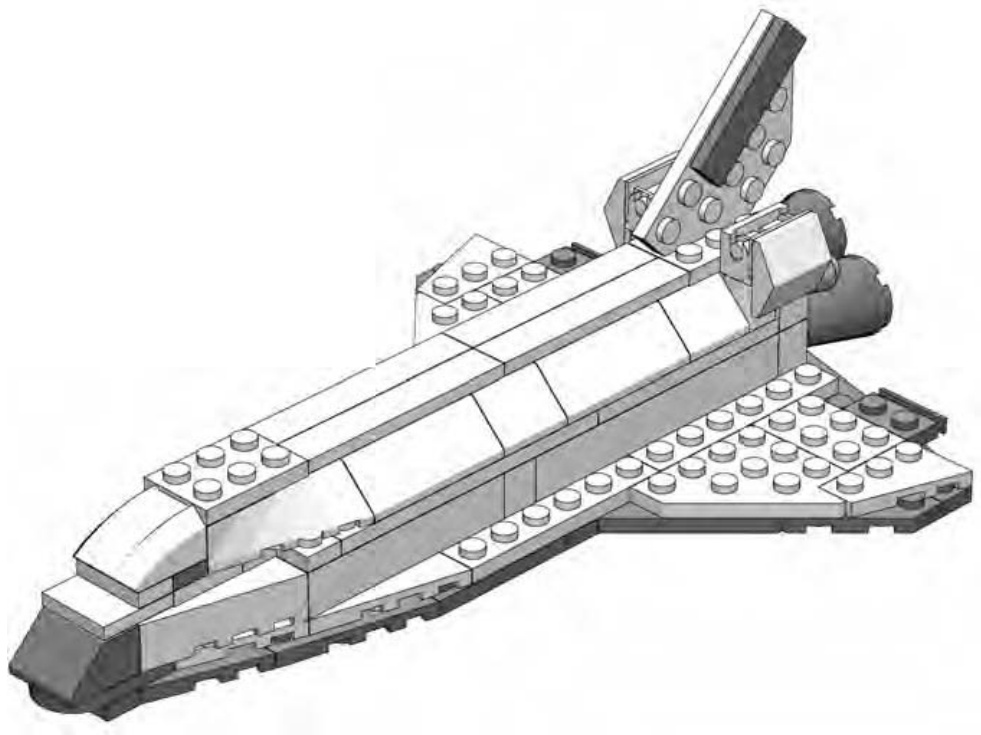
Figure 10-18: As long as nothing is blocked from view by the new elements, you can add any number of pieces in a single step.
In this step, you add the tail (mounted on a plate), the cowlings near the engines (the -degree slopes hanging off the brick hinges), and also the curved slope that becomes the top of the crew cabin.
Use a black tile on the tail to represent some of the protective material that is located there on the real shuttle. Don’t worry about re-creating the specific parts of the tail that move (located at the very rear). If you add in too much detail, this may take away from the look of the rest of the model. Remember that you don’t want to start adding a greater level of detail in one area if you are keeping other areas sparse.
The tail itself is held in place by the studs on the plate below it. The thickness of the plate is nearly identical to the distance between the studs. That’s what allows it to be wedged in like that.
Step 7
Sometimes you need to turn the model in one direction or another to more clearly see a building step. Figure 10-19 is an example of this. In this step, turn the ship so that the engines are facing the out. This allows you to see where the and cones that are used to create the engines go.
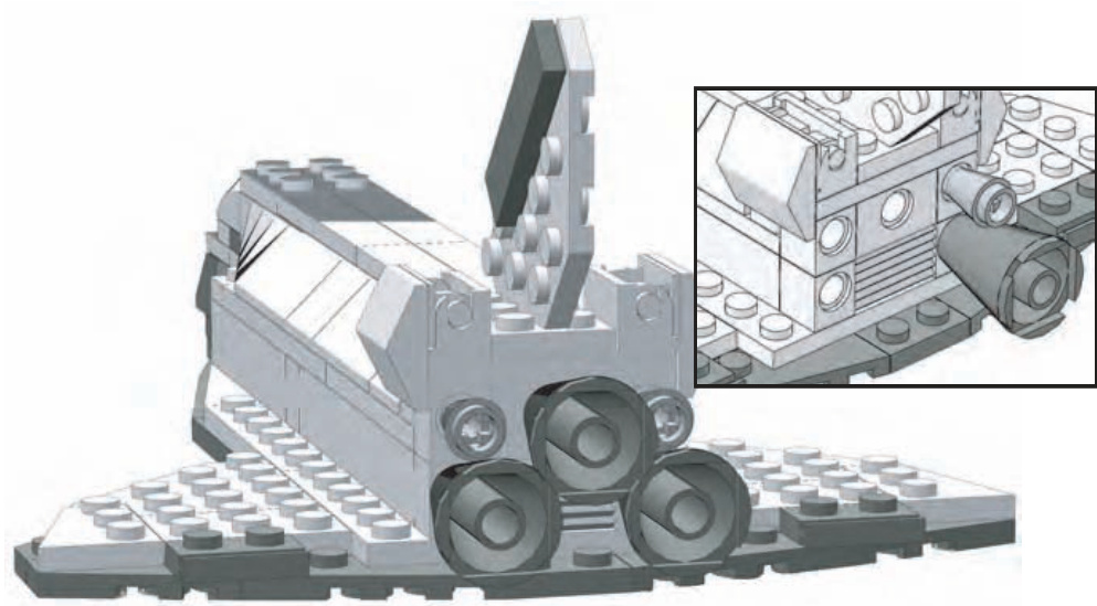
Figure 10-19: You now get to see why I used Technic bricks to build the end of the body. The insert shows the rear of the shuttle without all the cones in place. This should help you understand how I attached these pieces.
Although the engines might not be exactly the right size for this scale, they are very close. Additionally, they match the pattern in which the engines are mounted as accurately as possible. That helps better match your micro model with the real thing. Once again, it’s about capturing the look, not the minutest detail.
Step 8
Again, in Step 8, reposition the ship as shown in the illustration (Figure 10-20). This time, you’re looking at it from underneath so that you can see where to attach the landing gear. In a case like this where you are adding pieces to the underside of another element, you can count the tubes to see where to make the attachment. When you’re adding pieces on top of others, you usually use the studs as guides instead.
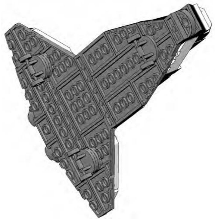
Figure 10-20: Using only a picture and no words, I can accurately describe where to attach the landing gear on the lower wing.
The two sets of wheels closer to the back are mounted slightly differently than the front landing gear. Each of the rear wheels has a cylindrical plate sandwiched between itself and the underside of the shuttle. This causes the nose of the craft to sit slightly lower when you are finished. You can see this effect in Figure 10-21 in step 9. This duplicates the angle at which the real shuttle points when it is taxiing after a landing.
Step 9
Figure 10-21 reveals that step 9 isn’t really a step at all; rather, it is an overview of what the completed model should look like.
Figure 10-21: The shuttle Triton parked in the classic nose-down position.
You might want to use this last step to determine where to add decals (printed from your computer) or small detail pieces. In this case (Figure 10-21), I just add a runway made of tiles beneath the model to give it a sense of realism.
Something’s Wrong: Redesigning Doesn’t Mean You’ve Failed
In the end, don’t be concerned if something isn’t quite right. This is a model made from LEGO bricks after all. Disassemble the section you feel is lacking and rebuild it using different pieces, different combinations of pieces, or alternate colors. In the case of the shuttle example, I built a prototype for the purpose of documenting it in this book. I rebuilt the nose two or three times before I hit on the combination of plates, tiles, and slopes that I felt best represented the shape I wanted to re-create. Similarly, I adjusted the pattern of plates I used to make the wings several times until I felt they looked right but were also strong enough to support the remainder of the pieces I was going to add on top.
The engines, on the other hand, were the first and only pieces I selected for that portion of the model. They just seemed to work right off the bat. The point is that not every section of a model comes together perfectly on your first attempt. Some turn out exactly as you intend, whereas others require you to change parts or techniques again and again until things begin to look better.
After You’re Done
Now you’ve seen how to design and build an original model from scratch. You’ve looked at various ways to capture details from real life objects and how to make wise design decisions when translating that object into LEGO pieces. When you’re done, you might find yourself asking, “What now?”
The first thing you’ll probably want to do is display your model somewhere so that other people can see it. The display might be real, such as in an office cubicle or on a shelf in your LEGO building area. For this, you might want to build something on which to set your model (such as the runway shown in Figure 10-21), or you may want to go even further and build a complete diorama in which to showcase it. Or, perhaps you want to display your model virtually. You can take pictures of it and display them on the Internet for your friends and others to enjoy. The choice is up to you, but chances are that once you’ve accomplished a successful design, you will want to share it in one way or another.
Review: Taking On the Role of Model Designer
You don’t have to be hired by the LEGO company to be a model designer. The moment you decide to build something that’s never been built before, you cast yourself into the role of designer. That’s really what this book is all about. You will need all of the tools around you—part selection, color choices, scope, and scale—to make good decisions about the models you will design. But working through those decisions adds great dimension to this hobby. Enjoy your new job!
11 B E Y O N D J U S T B R I C K S : O T H E R T H I N G S T O D O B E S I D E S B U I L D I N G
Some hobbies are limited in just how much you can do with them. For instance, if you’re a coin collector, you can collect coins, look at them, and not much more. Although there’s nothing wrong with this activity, it doesn’t offer you many new possibilities if you find yourself getting tired of just looking at your coins. LEGO, on the other hand, allows for activities not always directly related to just building with bricks. This chapter covers three different variations on the LEGO hobby.
Reviews
If you’ve purchased an official LEGO set, you might want to share your experience building it with other LEGO fans. Writing a good review can be an exercise in both language skills and in learning to evaluate rationally.
Instructions
When you create a model on your own, sometimes you want to share the build information with others so that they can build their own copies. Another way that you can extend the LEGO hobby is to use your computer to create usable instructions for models.
Games
You also have the potential to mix games and LEGO together. You can do this in two ways: either by re-creating some of your favorite existing games or puzzles (checkers, chess, concentration, and so on) or by inventing new games of your own.
“I Give It a Nine Out of Ten”: Writing Reviews of LEGO Sets
You’ve probably discussed a recent movie or a CD with friends. If you really liked the film or the music, you also probably tried to tell your friends why they should take the time to experience it. If this sounds familiar, it’s probably not difficult for you to imagine what you’d do if you received a great LEGO set—you’d want to tell other people about it. The easiest way to do this is to write a review of the model that you’ve bought, built, and enjoyed.
A Simple Review
You may have already seen reviews of LEGO sets posted on the Internet. In some cases, these critiques can be very detailed; they may describe various aspects of the set such as playability, specialty parts, design strengths, etc. However, your review doesn’t have to be long and complicated in order to be effective. After all, part of the goal of a review is to express your fondness, or lack of enjoyment, of a particular set.
Your review can take many forms. You may wish to simply write a couple of paragraphs describing what you did and didn’t like about the set. If this is the case, your review may end up sounding similar to a movie or book review. You might even decide to give the set a thumbs up or thumbs down as the case may be. On the other hand, you might want to start with something a little more structured, like the simple format described next.
Basic Set Review Form
In this section, you’ll find a template you can use to create simple reviews of just about any LEGO set. The bold words indicate the different sections of the form. Keep them as they are. The descriptions that follow each section heading are just ideas of what you might put for your own review.
Set Name/Number
Almost every official LEGO set has a name and product number to identify it.
Number of Pieces
This number is usually printed somewhere on the box. It gives people a sense of how big this particular set is.
Type of Instruction Book
Did the set contain instructions for just one model? Or perhaps it’s an “idea” book that just gives you suggestions for things to build.
Price
This is usually given as the before-tax price. Be sure to include the currency to which you are referring.
Set Description
A brief overview of the set. You could include the theme, the overall size, and whether or not it is minifig scale; you could even note things like the type of packaging or where you purchased the set.
Notes
This is the heart of the review. This is your chance to tell everyone what you liked/disliked about the set. Write a few paragraphs as a general commentary about your experience building the model.
Rating
Since it’s your review, it’s entirely up to you to decide how to rate the set. You can use a scale of 1 to 10 bricks. Or perhaps something like good, better, best. Or you can make it as simple as saying, “I give this set a thumbs up.”
Sample Review
This section provides you with a sample review that uses the template that I just described. In this case, I’ve used the space shuttle model from Chapter 10 as the subject for the review (Figure 11-1).
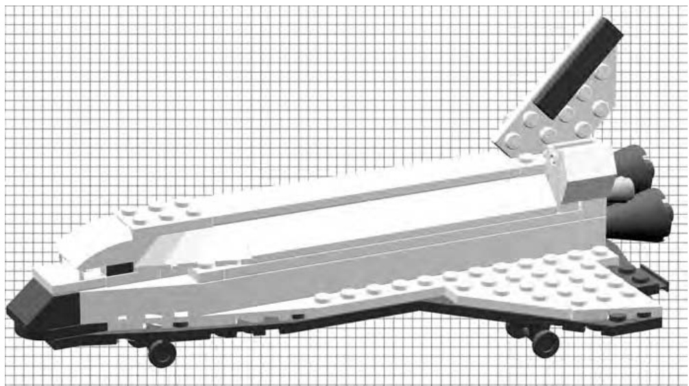
Figure 11-1: The shuttle model we designed and built in Chapter 10 becomes the basis for our sample set review.
You won’t normally write reviews about your own sets, but this provides an example with which you’re already very familiar.
Set Name/Number Space Shuttle Triton (Set #0001)
Number of Pieces 99
Type of Instruction Book
Computer generated; 9 steps. Main model only, no alternate models.
Price N/A
Set Description
The model of the fictional Space Shuttle Triton is much smaller than minifig scale, though not quite microscale. It would make a suitable display model on a shelf or even on top of a computer monitor.
Notes
The model makes good use of wing plates to help create the distinctive shape of the shuttle’s wings. The simple color scheme (black and white) of the real vehicle translates well into LEGO bricks. A single bow plate is mounted on an angle to create a realistic-looking tail. I think the landing gear looks a bit too big for this scale, but it does steady the model when it’s placed on a table or shelf. Overall, it’s a clean, simple model, although it lacks much of the detail that could be captured in a larger scale.
Rating
I’ll give this one a thumbs up, ready for launch!
Sharing Your Review
If you’re creating your review for your friends, it might be enough to simply send them a copy (perhaps via email) so that they can know your feelings about the set. On the other hand, you may wish to post the review to a LEGOrelated website and share it with an even wider audience.
NOTE Check out www.apotome.com/links.html for a list of LEGO-related websites where other builders share their reviews, models, and ideas.
The time and effort you put into providing a fair review of the set will likely help someone else make the decision of whether or not to buy the same thing.
How It’s Made: Creating Instructions for Your LEGO Models
In the last chapter, you created a model from scratch. You designed and built a small version of NASA’s well-known Space Shuttle. Hopefully, by using some of these techniques you will create your own original models. At some point though, you’ll want to take that model apart to re-use the pieces. How will you remember everything you need to re-create the model in the future? It’s simple—you just need to document the parts and the steps you used to arrive at your final design.
Many of the LEGO sets you already have probably came with instructions. You might look at them and wonder how you can create such detailed plans for a model. Luckily, there are ways to create these instructions that don’t require a degree in fine arts in order to make them useful.
Step-by-Step Pictures
One easy method you can use to create plans for your model is to simply document your building process step by step with a digital camera. The fact that there is no film to develop and print means that you can take as many pictures as you need to fully explain how to obtain the desired results.
First, you can take a picture (or several pictures) of the parts used to build the model, as shown in Figure 11-2.
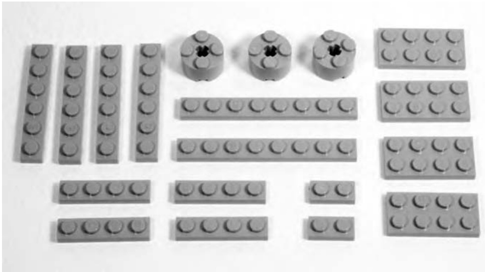
Figure 11-2: Set out the parts for the model and take a picture of them before beginning construction. In this case, I show the pieces needed to build a 4X plate.
The elements shown in Figure 11-2 give the builder a clear picture of what parts they’ll need to build the model.
Then capture each step, right after you’ve added the parts for that step to the model. Figures 11-3 and 11-4 show sequential steps for building a plate in 4X scale. You saw this same model back in Chapter 5 (Figure 5-19).
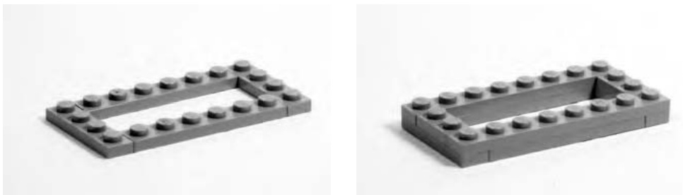
Figure 11-3: Each photograph should show a single step in the construction of the model. Here are steps 1 and 2 of the plate in 4X scale.
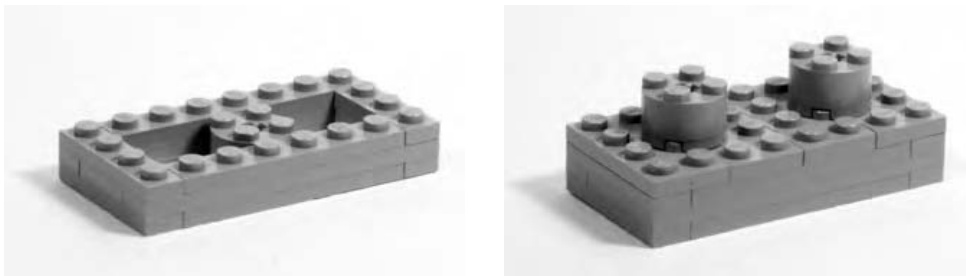
Figure 11-4: Each subsequent picture should show the model from the same angle but with more parts added. Here you see steps 3 and 4.
You can then import these pictures into a word processor so that you can create instructions for them, all as a single document. Or, alternatively, you can post them to the Internet and let people view them one at a time. Either way, the pictures are an effective way to share your building techniques or even to just remember how to build a favorite model again in a few years.
Computer-Assisted Instructions
Throughout this book, you have seen instructions for a number of different examples. I created most of these images using computer software (LeoCAD) that allows me to build virtual models. Similar to programs that are used to design cars and airplanes, these amazing utilities provide an endless supply of LEGO bricks in every color you need. You can design and build the entire model, as seen in Figure 11-5.
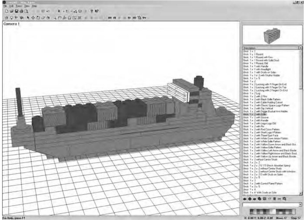
Figure 11-5: LeoCAD is one program available to help you create virtual LEGO models. With this and other programs, you never run out of elements.
NOTE For a list of software and websites that will help you to create your own computergenerated LEGO models and instructions, please visit www.apotome.com/links.html.
These programs also enable you to track each step as you go and then use that information to create step-by-step instructions that other builders can follow. Figure 11-6 shows an example of these types of instructions taken from Chapter 5.
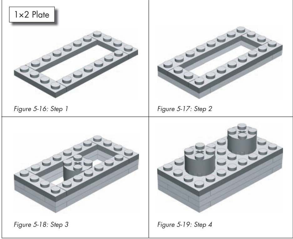
Figure 11-6: An example of instructions created using computer software. Notice how similar these images appear to Figures 11-3 and 11-4.
Having Fun: Making and Playing Games with LEGO Pieces
The word “fun” is often associated with the LEGO hobby. To take the fun even further, you can combine your LEGO elements with games you already know (by re-creating them in LEGO pieces) or you can create games that are completely original.
Games You Already Know
A number of traditional games are played on a checkerboard-styled playing surface. This board typically has 8 squares along each side, for a total of 64 squares.
Interestingly, the LEGO company makes a waffle-type baseplate that is 32 studs along each side. When you divide 32 by 8, you’ll quickly realize that this large LEGO baseplate can be broken up into squares that are four studs long on each side.
As you can see in Figure 11-7, it only takes a few tiles to make up each square on the game board.
Figure 11-7: Four tiles are used to create each different-colored square on the game board.
If you don’t have quite as many tiles as you need to completely cover a baseplate, you can use two different colors of standard plates. It won’t look as smooth, but it should be just as useful for playing games.
Once you’ve made a board like this, you can use it to play games like checkers or chess. As you can imagine, to play a game of checkers on a LEGO game board, all you really need are simple playing pieces. In fact, they can be as simple as bricks in two different colors.
To enjoy a game of chess, however, you might consider creating your own custom set of chessmen. You’ve probably seen different chess sets, some with traditional style pieces and others that have pieces that reflect a theme of some sort. Using LEGO elements, it’s possible to create whatever style chess pieces you prefer. Figure 11-8 shows a simple traditional pawn. It uses mostly common parts, so building eight of them shouldn’t tax your collection too much.
And whereas the rook, shown on the right in Figure 11-9, is fairly traditional, it also is a good start to a medieval-themed set of chess pieces. The bishop shown on the left in Figure 11-9 is fairly plain, but it does have the pointed top that is commonly associated with this piece. These are just some examples to get you started. Creating your own themed chess set can be a fun exercise.

Figure 11-8: A basic chess pawn made from LEGO elements.
Figure 11-9: These two examples are both built on bases.
Original Games
In Chapter 10, you tackled the challenge of designing your own LEGO set. For another interesting activity, you might try using LEGO pieces to create your own original game, complete with rules on how to play.
As an example, I’m going to present a game that I originally designed to be played on wooden tiles using glass bead markers. The game is called Connect-Across, and the basic rules follow momentarily. As you’ll see, it works just as well when you make it from LEGO pieces.
To get ready to play, you simply need to make 30 tiles or squares similar to those in Figure 11-10.
Figure 11-10: These are two examples of how you can create the tiles. Pick either style or work on one of your own. You’ll need 30 identical tiles to play the game.
It’s not important which style you use, so long as all the tiles are the same size. Additionally, they don’t all need to be the same color; they can be any combination of bricks and/or plates that you have in your collection.
You also need two sets of playing pieces. Each set should consist of 15 identical markers, for a total of 30. You can pick from one of the styles shown in Figure 11-11 or come up with something similar on your own. The only thing to keep in mind is that the two sets of pieces should look different from each other.

Figure 11-11: Several different styles for markers that can be used to play the game.
For example, for the first set, you could use 15 upside-down wheels (with or without the rubber tires) like the one shown on the far left of Figure 11-11. Then, for the second set of pieces, you could make 15 copies of the marker shown on the far right of Figure 11-11.
Once you’ve built the pieces you need (just described), you’re ready to play your first game. Here are the complete instructions to get you started.
An Example of an Original Game: Connect-Across (Basic Rules)
Connect-Across is a game that combines the basic goal of tic-tac-toe with the light strategy involved in checkers. You and your opponent build the board together as the game progresses, while at the same time, you try to get four of your own pieces aligned in a row.
Setting Up
Decide who is going to use which set of markers. You may wish to build one set using light-colored elements and the other using darker elements. Have each player set his or her 15 markers near them on the table.
Set aside four of the square tiles.
Give each player about one-half of the remaining tiles. The tiles are all the same, and it doesn’t really matter which ones you get or if you get exactly half of them.
Decide who is going to go first. You can do this with the flip of a coin or by any other means.
The player who is selected to go second actually completes the setup part of the game. They do this by taking the four tiles set aside earlier and arranging them in the center of the table (see Figure 11-12 for an example). These tiles may be set out in any pattern, as long as each tile is touching the side or corner of one of the others. In other words, you can’t have any tiles floating free, away from the remainder of the group.
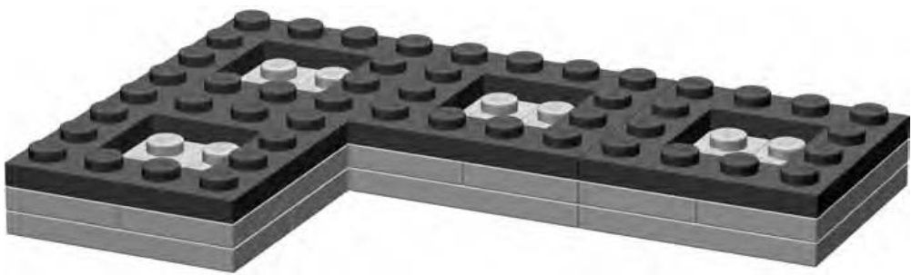
Figure 11-12: Here is only one example of an opening pattern. The tiles can be in any arrangement, as long as they are all touching.
You may wish to use one of the large waffled baseplates on which to set your tiles. This keeps them from shifting around too much. However, it’s not at all necessary—the game should play just as well on any level surface.
How Is It Played?
It’s important to understand that there are really only three basic rules for playing Connect-Across. These rules dictate what you can do any time that it is your turn. During your turn, you can make any one of the three following moves:
-
Place one of your markers on any open tile that is already part of the board.
-
Place a new tile on the table, making sure that it touches the side or corner of another tile that is already part of the board.
-
Move one of your markers that is already on the board. This movement can be a single space, to an adjacent and empty tile, or, it can be a capture jump just like in checkers. In this case, your piece leaps from its current position on the board, over an opponent’s piece, and lands on an empty square. The piece you jump over is removed from the board and returned to its owner.
And that’s it.
Playing the Game
To begin a game, the person who won the coin toss has a choice of either of the first two rules. (There are no markers on the board yet, so rule 3 is unavailable at first.) The first player may either place one of their markers on any one of the four empty squares, or they may instead choose to place a tile on the table, thus increasing the size of the game board. Remember, the tile can be placed anywhere, as long as it touches an existing tile on either an edge or at a corner.
Figure 11-13 shows one example of an opening move. In this case, the player using the light colored markers has placed one of their pieces on the board. They could have chosen to set down another tile instead.
Figure 11-13: The upside-down wheel makes an effective yet simple marker, and it fits perfectly in the center of a tile.
The game then shifts to the other player. Again, they may choose from either rule 1 or rule 2 initially. They can place a marker or place a tile.
Players continue to take turns making moves in a similar fashion. Of course, once either player has placed at least one piece on the board, they may decide to use rule 3 on any of their subsequent turns. Remember that you can pick any of the three moves you want, but you can only make one move during each turn.
What you will notice is that the board soon begins to grow in a rather organic fashion, with rows and columns branching out in many directions. You’ll likely find that no two games are ever played on the same shaped
board. Figure 11-14 shows a game in progress. You can see that the player using the light-colored markers has a good chance of making four-in-a-row diagonally through the middle.
Figure 11-14: Getting four in a row may not be as easy as you think!
Winning the Game
Players continue to add tiles or markers and make single or capture moves until one player is able to get four of their own markers lined up in a row. The row may be vertical, horizontal, or diagonal along four adjacent tiles with touching corners. You can see an example in Figure 11-15. The player using the light-colored markers has created a diagonal row. Follow the wheels from the bottom center of the picture toward the top. The first player to accomplish this wins the game.
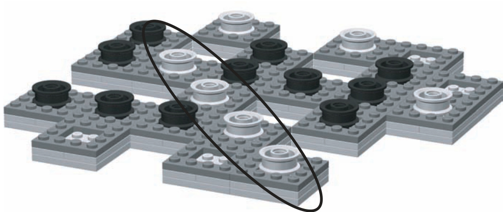
Figure 11-15: The oval highlights the winning move in this particular game.
Designing Your Own Game
Creating your own original game is one part inspiration and 99 parts play testing. A lot of ideas sound good on paper and may even look good if you create the board and playing pieces for them. But many games end up being too complicated, too confusing, or just plain boring. Play testing involves actually sitting down with other players and observing your game in action. It helps you find areas that need improvement and allows you to adjust the rules to make the game more fun.
When you’re thinking about making your own game, try to think about the following:
What is the main point of this game?
How can I use LEGO pieces to help bring this game to life?
What makes this game different every time it is played?
Will the game have a theme or will it use abstract pieces like checkers?
What makes it challenging?
How can I keep the rules simple but at the same time create interesting
twists?
If you can come up with good answers to some of these questions, you are well on your way to designing a fun and exciting game. The next step is too build a prototype of the game. This is essentially a copy of the game you can try out by play testing. Find a friend who enjoys games and get them to walk through the game a few times with you. It won’t take long to find the parts that don’t work well and to recognize areas that you can tweak to make things more lively. The LEGO system is perfectly suited to building game prototypes; after all, building things is what it does best.
Review: Enjoying Every Aspect of LEGO
How you choose to enjoy LEGO as a hobby is entirely up to you. As you’ve seen in this chapter, there are ways to add interest to your LEGO elements that don’t involve just building models. Just as with the building techniques you’ve explored in this book, there is no one right or wrong way to enhance your participation in this hobby. That’s why writing reviews, playing LEGObased games, or creating instructions can be just as rewarding as building the models themselves.

S O R T I N G , S T O R A G E , A N D S I T T I N G D O W N T O B U I L D S O M E T H I N G
When most people think of storing a bunch of LEGO bricks, they think of that plastic tub or maybe that cardboard box a lot of kids have. It’s chock-full of assorted parts from a number of different sets and gets dumped on the living room floor when friends or cousins come to visit. It offers ease of use, but it does not really allow any sorting of bricks into meaningful batches.
That box is probably suitable if you have a few thousand LEGO pieces or less. But if you have more than 5,000 or 6,000 elements, you might find that it is getting not only heavy but also crowded. Once you have more than 10,000 bricks, it’s time to do some sorting. Figure 12-1 shows that it only takes a few dozen pieces to make a pile that needs sorting.

Figure 12-1: Unruly bricks ready to be sorted
At some point in your building career, you will need to begin the process of sorting your pieces into smaller containers. For some people, this is the least enjoyable part of the LEGO hobby. For others, this process is a pleasant change of pace from building or planning models. No matter what your take on the subject, you must eventually decide how to sort and store your collection.
First let’s separate this topic into its three main components:
Sorting bricks
The system or method by which you separate bricks into piles/ categories.
Storing bricks
The physical boxes, containers, and drawers that sorted bricks go into.
Setting up a build area
The type and quantities of bricks you keep readily available and the area you set aside for working in.
Sorting vs. Storing: What’s the Difference?
Although sorted bricks are often stored in the manner in which they’ve been divided up, there is a distinct difference between the system you use to sort and the containers into which you place your sorted pieces. Think of the process of sorting as being similar to that you’d perform on a list of phone numbers and email addresses for your family and friends. You might sort this list alphabetically, by the length of time you’ve known the person, by where they live, or by group (friends, family, coworkers, and so on). However you approach it, this is your method of sorting.
Once it’s organized, you might decide to store this information in a small book with lined paper and lettered tabs, you might type it onto one long sheet of paper so you can keep it in your wallet, or you might decide to use some computer software (like an email program) to store it electronically. Whatever you decide on is your system of storing.
In the next section, you will focus exclusively on sorting. You can, for the moment, assume that you’re just making piles of bricks on the floor or on a table, such as the small piles shown in Figure 12-2.
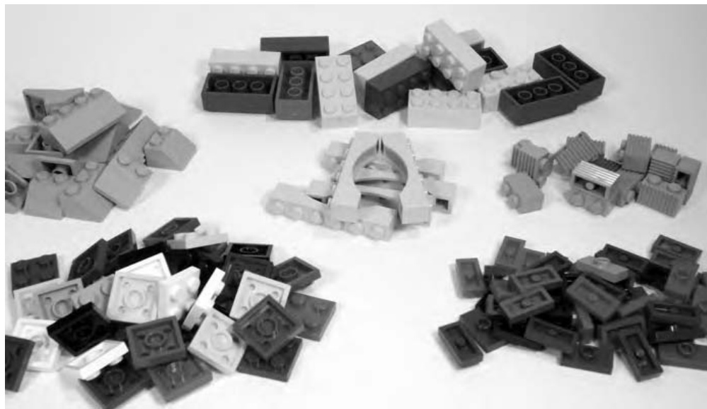
Figure 12-2: These pieces have been sorted but not yet stored.
You will look at various ways to determine what goes into each pile. Later, I’ll talk about what kinds of containers you can use to store these piles.
Sorting Bricks: Divide and Conquer
The most common question asked when people begin to talk about sorting is, “Should I sort by color or by shape?” The answer is not as cut and dry as just choosing one style or the other. The answer depends upon such things as the size of the collection being sorted, the space and containers you have available in which to store your bricks, and even what type of models you’re building at any given time.
The first thing to look at is the collection of bricks that you’re attempting to sort. Let’s sort two imaginary collections, with simplified inventories, to help illustrate the techniques.
Small-Sized Collections
Collection #1 (Table 12-1) presents an interesting challenge. For whatever reason, you have a particular piece that is present in very large numbers; you’ve got about red bricks. If you decided to store all the pieces from this collection in a single pile, it might be tricky to find a plate when you needed one. However, if you create two piles, one for the bricks and one for everything else, it’s more likely that you can find a part that isn’t a . When you need a , of course, you know that they are in their own pile.
Collection #2 (Table 12-1) is a bit different. Here you have a limited supply of red bricks but a slightly larger and more varied list of red plates. If you mix all the bricks and plates together, it might make it harder to find some of the small plates. In this case, your plates are not really dominated by a huge number of any one particular piece. In other words, your collection falls into two camps: bricks and plates. Why not create two piles to represent that fact?
Table 12-1: Inventory for Two Small Collections
| Collection #1 | Collection #2 | ||
| Quantity | Type of Elements | Quantity | Type of Elements |
| 10 | lxl red bricks | 10 | 1xl red bricks |
| 5 | 1x4 red bricks | 5 | 1x4 red bricks |
| 500 | 2x4 red bricks | 20 | 2x4 red bricks |
| 50 | 2x6 red bricks | 25 | 2x6 red bricks |
| 6 | 1x4 red plates | 50 | 1x1 red plates |
| 10 | 1x8 red plates | 200 | 1x2 red plates |
| 20 | 2x4 red plates | 6 | 1x4 red plates |
| 10 | 1x8 red plates | ||
| 20 | 2x4 red plates | ||
| 20 | 2x6 red plates | ||
| 10 | 2x8 red plates | ||
| 4 | 4x4 red plates | ||
| 4 | 4x6 red plates | ||
These examples are a little simple. Let’s look at some larger lists of bricks to see others way to sort them.
Medium-Sized Collections
In Collection #3 (Table 12-2), you have about the same number of red bricks as you had in Collection #2 (Table 12-1) but a few more red plates. In addition, you now have two additional colors to deal with as well; there are both blue and white plates in this collection. The quantity of red plates still dictates that they have their own pile. The bricks, since they are different types of pieces, belong in their own pile as well. This leaves you with just the blue and white plates.
Table 12-2: Inventory for Medium Collection
| Collection #3 | |
| Quantity | Type of Elements |
| 10 | 1xl red bricks |
| 5 | 1x4 red bricks |
| 75 | 2x4 red bricks |
| 25 | 2x6 red bricks |
| 50 | 1x1 red plates |
| 200 | 1x2 red plates |
| 6 | 1x4 red plates |
| 10 | 1x6 red plates |
| 10 | 1x8 red plates |
| 20 | 2x4 red plates |
| 20 | 2x6 red plates |
| 10 | 2x8 red plates |
| 4 | 4x4 red plates |
| 4 | 3x3 red diamond-cut plates |
| 16 | 1x4 blue plates |
| 30 | 2x4 blue plates |
| 25 | 2x6 blue plates |
| 2 | 2x8 blue plates |
| 2 | 4x4 blue plates |
| 20 | 1×2 white plates |
| 10 | 2x4 white plates |
| 5 | 2x6 white plates |
| 6 | 2x8 white plates |
| 4 | 4x4 white plates |
There really aren’t enough of either color to warrant a separate pile just yet. Because the two colors are far apart in tone, you can safely mix them together, confident that such a small pile will be easy enough to search for a piece of either hue.
Let’s look at one more example.
Large-Sized Collections
In Collection #4 (Table 12-3), you’ll look at a wider variety of parts and try to see what the best way is to break them down into separate piles.
Table 12-3: Inventory of Larger Collection
| Collection #4 | |||
| Quantity Type of Elements | Quantity | Type of Elements | |
| 100 | 1x1 red bricks | 4 | 2x8 red plates |
| 5 | 1x4 red bricks | 4 | 4x4 red plates |
| 175 | 2x4 red bricks | 16 | 1x4 blue plates |
| 25 | 2x6 red bricks | 30 | 2x4 blue plates |
| 250 | 1x1 yellow bricks | 25 | 2x6 blue plates |
| 15 | 1x4 yellow bricks | 2 | 2x8 blue plates |
| 20 | 1x6 yellow bricks | 2 | 4x4 blue plates |
| 70 | 2x4 yellow bricks | 20 | 1x2 white plates |
| 125 | 1x1 white bricks | 10 | 2x4 white plates |
| 20 | 1x2 white bricks | 5 | 2x6 white plates |
| 20 | 1x3 white bricks | 6 | 2x8 white plates |
| 30 | 1x4 white bricks | 4 | 4x4 white plates |
| 10 | 1x8 white bricks | 5 | 1x3 33 deg white slopes |
| 80 | 2x4 white bricks | 4 | 1x2 45 deg white slopes |
| 50 | 1xl red plates | 10 | 4x3 33 deg black slopes |
| 20 | 1x2 red plates | 6 | 2x3 33 deg black slopes |
| 10 | 1x6 red plates | 2 | 1x4 red arches |
| 2 | 1x8 red plates | 2 | 1x6 red arches |
| 10 | 2x4 red plates | 4 | red bullnose bricks |
| 6 | 2x6 red plates | 6 | white headlight bricks |
Now this is a more realistic collection. Your own collection will almost certainly have a wide variety of pieces. It will probably include more colors and types of pieces than are showing here, but for this exercise, this pretend collection will suffice.
Start with an easy decision. If you look at the top of the list, it’s clear that there are a lot of bricks, in three different colors. To make them easy to keep track of, give them their own pile. ’s can, in fact, be mixed in with other larger bricks, but when you do this, they have the tendency to filter down to the bottom of the container and, as a result, become more difficult to find.
Next, you have a little more complicated decision to make. Take a look at just the and bricks near the top of the list. How you split these up can go a couple of different ways. You can separate all the bricks into one pile since, collectively, they contain more pieces than the rest of the bricks put together. Doing so would leave the bricks (of all three colors) to make a pile of their own. On the other hand, you can sort them exclusively by color. Doing so would give you one pile each of red, yellow, and white bricks. It is likely, that no matter which of these choices you prefer, you’ll still want to have your ’s set aside so they don’t get lost.
A subtle twist on the last separation is to take all of the smallest bricks (the ’s and the ’s) and set them apart as one pile. Then, no matter whether you go with the split or you decide to separate by each of the three colors, you still have your less visible bricks separated from the rest, thus making them easier to find.
Now it’s time to sort the plates. This collection has fewer red plates than did the others. As a result, it might be reasonable to make a single pile that gathers all of the plates together. Once again, you are looking at the current quantities you have on hand so that you can decide how best to find a certain piece in a particular color when you are building your next great model later on.
Collection #4 has a few things you didn’t see in the other lists. First are the slopes. The black slopes are larger than the white ones, but there is not a significantly larger number of the black ones for them to require a pile of their own. In fact, because the two colors are exact opposites, storing them together is not a problem. A single pile will do for all the slopes.
Finally, look at the very bottom of the list; you’ll see some bricks that you have yet to categorize. Based on what you learned in Chapter 1, you know that each of the last four items in this collection are specialized elements. In some ways the specialized elements category is the miscellaneous category for classifying bricks that don’t meet other criteria. As the name suggests, almost all of these bricks provide a special function unmatched by typical bricks, plates, or slopes. Based on the small number of specialized elements in this collection, they can simply share one pile.
In a larger actual collection, however, a particular service element may require a pile unto itself. An example might be the offset plates. These relatively common parts are available in a wide variety of colors. Once you have a few dozen or maybe even several hundred, you may want to keep them separate from other pieces. You’ll find that this becomes doubly effective when your many offset plates are in 6, 8, or 10 different colors. Keeping them in their own pile allows you to more easily find a handful in just a single color.
The specialized parts in Collection #4 are probably just as noticeable when you keep them together. This remains true until you find that the quantity of one of them has grown to such a level that it requires its own area as well. This process, of redeciding how to sort some elements pops up again and again. Each time you add a large set (or a number of small sets) to your collection or you buy a number of assorted buckets or tubs, or you find yourself buying parts in lots from an online auction or sales site, you may find that you need to extract one or more parts and give them a pile, or piles, of their own.
Storing Bricks
Until now you’ve focused exclusively on putting your parts into piles based on a number of guidelines. But unless you have unlimited amounts of table space on which to keep your bricks, it’s very likely that you’ll want to find a better way to store them. Storing refers to keeping the bulk of your collection on shelves or in a closet and bringing out only what pieces you need, when you need them. As we discussed earlier in this chapter, the topic of storage is related to, but also separate from, how you sort your bricks. The shelves in Figure 12-3 show how a medium-sized collection might look when stored in a variety of containers.
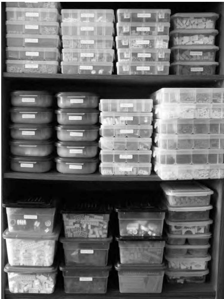
Figure 12-3: Different-sized containers work together to form an effective storage system.
You can see that this collection has been broken down into a number of different-sized containers. Your collection will likely end up stored in a similar manner. But what size boxes should you use? Different pieces have different needs; especially when you take into account how many of each you own. Let’s look at several different-sized containers to see how each can be useful.
Start Small, Keep It Simple
One of the smallest boxes that I came across when first storing my collection was an empty videocassette case. No, I don’t mean the cardboard sleeve that has the movie’s title printed on it; I’m talking about the hard plastic replacement cases that you can often find at stores in packages of 2 or 3 at a time. The best ones I found were translucent white, like the one shown in Figure 12-4. These little boxes are cheap and very handy for those little piles of 20 or 30 pieces—maybe some slopes you have in an uncommon color or perhaps a pile of ’s and plates in some of the new pastel colors. It could be anything, but the point is that there isn’t much sense in dedicating huge amounts of space to parts you don’t yet have. The videocassette cases are also great for storing tiny things that might get lost at the bottom of a larger, deeper container. These could be things like minifig accessories, small plates or tiles, Technic pins and gears, and so on. Additionally, you can store the boxes themselves inside larger LEGO tubs that you may already have. (More about those tubs follows.)
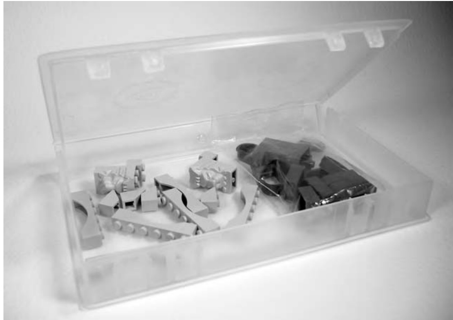
Figure 12-4: Even the smallest container can add a great deal of organization to your collection.
Containers with Compartments
If you are looking for something a little larger than videotape cases, you might want to turn to leftover containers. These are plastic containers about the size that you’d find useful for storing leftovers after a big meal, and they are available in your grocery store or discount store. There are brand-name and no-name versions of these, and there is a large range of quality when it comes to how they are manufactured. These containers offer one immediate advantage over almost any of the other types of storage media, however: they are available in a huge number of shapes and sizes.
Some of my favorites in this category are, in fact, not suitable for leftovers at all. They are the right size for a small meal, but they are all a lower quality no-name brand that is not airtight. I wouldn’t want to keep last night’s lasagna in them, but the lids do stay on. Because LEGO bricks don’t need to maintain that just-picked-this-morning freshness, these containers work wonders for storing medium-sized piles.
Some plastic containers, like those in Figure 12-5, have two or more compartments. This allows for some useful storage solutions, such as keeping your standard and inverted slopes separate but also together. This is a case where you can truly merge your sorting and storage techniques in one place. The container maximizes the organization you’ve been working to achieve. In this example, you can pull a single box out of your main storage area, bring it to your building area, and have at your disposal two or three types of useful, and at the same time related, pieces.
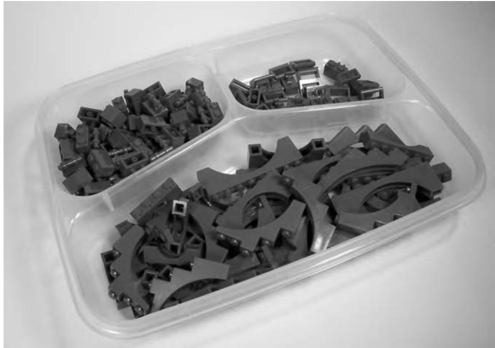
Figure 12-5: No, it’s not a TV dinner, but the shape of this container might remind you of food nonetheless.
You may run across all kinds of versions of these containers. Unlike shoebox-sized boxes, leftover containers tend to vary widely in size, shape, number of compartments, depth, and so on. You might want to shop around before buying any of them at all. It’s very likely that you can find some of them at dollar stores or other discount retailers for very little money. Or, on the other hand, you may wish to spend a bit more on some brand-name containers so you know that they will, in all likelihood, never wear out. Sometimes you get what you pay for.
In addition, you’ll want to have a sense of what sizes and shapes are available in your area and compare that to the piles you have sorted your pieces into. In my case, I have three distinct styles of leftover containers that I use to store my collection. I settled upon each of these because it was useful, inexpensive, and readily available. Your decision on which ones to buy should be based on similar criteria.
Suppose you have a large number of standard blue slopes and inverted blue slopes in your collection. Over time, you’ve acquired a number of copies of a particular assorted tub of bricks that each contained several pieces of these two elements. During your sorting process, you probably gave these parts their own pile because you had a healthy handful of each. At this point, for storage purposes, you may decide that you want to keep the regular slopes somewhat separate from the inverted ones, while still keeping all of these blue elements together. In a case such as this (similar element with two variations), you could adopt a single container that is or can be divided into two sections. Or, you could use a single container and just divide the slopes and inverted slopes into two different resealable plastic freezer bags before placing them inside.
Shoeboxes: Not Just for Shoes Anymore
In addition to the blue-sloped pieces just discussed, assume that you also have about 50 or 60 red roof bricks (another name for 33-degree slopes) that you won on an eBay auction for a really good price. However, in the rest of your collection, you don’t really have many more slopes in any great numbers. Now you’ve got your blue (regular and inverted, from the last section) and red slopes that you need to keep separate from other elements in your collection. In this case, a small plastic container (one about the size of a shoebox like the one shown in Figure 12-6) might work best; it can hold each of the three distinct elements, each in its own freezer bag. In other words, your red and blue slopes will all share one box, but they’ll each be easily accessible since they’ll be kept separate by the plastic bags.
The box I’m talking about here can often be one that you find at a nearby dollar store, or perhaps at a home decorating store in the storage aisle. These don’t have to cost a lot of money, but they can be enormously effective as storage solutions for a small- to medium-sized LEGO collection. They are available in more expensive brand-name versions, but since you don’t require water- or airtight containers, any generic box will probably do just fine.
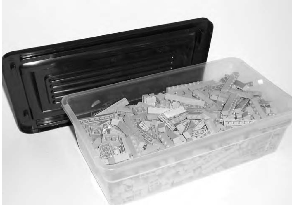
Figure 12-6: One of the most useful sizes of containers to consider buying
Boxes of this size offer the additional flexibility of being easy to house on shelves, in a closet, or even under a bed if need be. An average sized box of this type can easily hold a couple of hundred bricks, several thousand bricks, and so on.
These boxes offer other benefits. They are easy to move from a shelf or cupboard to the area where you are going to build. In addition, many of them are translucent, so the contents are not hidden from you. In fact, most of my shoebox-sized bins are not labeled because I can view their contents by looking through their sides. They are also large enough that for many building projects, a single box (of a single color or part type) offers enough pieces that you don’t have to go into your deep storage. (More on deep storage coming up later in the chapter.)
There is yet another way to make this type of container even more useful. You can store elements that are related in some way, but that you still want to keep separate, together in these containers. You do this by first putting each pile of elements into a zip closure freezer bag and then putting those bags into the shoebox. For example, you may wish to store standard and inverted slopes of the same color in this manner.
Keep in mind that until you’ve worked with your collection for a while, and have perhaps sorted it once or twice, you may not wish to invest heavily in one specific type of container. For instance, if you’re not sure that the shoebox-sized plastic tubs will be big enough, why not use actual shoeboxes for a while? Most households have a handful of such boxes around, and they can be pressed into service to act as test units for your storage needs. You can easily affix a simple piece of paper that lists the contents of the box to the front to help you tell the boxes apart. Although these won’t be as uniform or tidy as the plastic boxes, they also won’t cost you any money. If, in a few months you find that they are, in fact, useful as a storage medium, you might then want to invest in more permanent versions.
Keeping Track of the Little Pieces: Tackle Boxes to the Rescue
What about all those really small pieces you end up with? They might be cylinder plates, or Technic pins, or maybe minifig accessories. They can be difficult to keep track of, even in a very small container. The solution is to use a larger container that is divided into very small compartments. The most common of these are similar to the one shown in Figure 12-7.
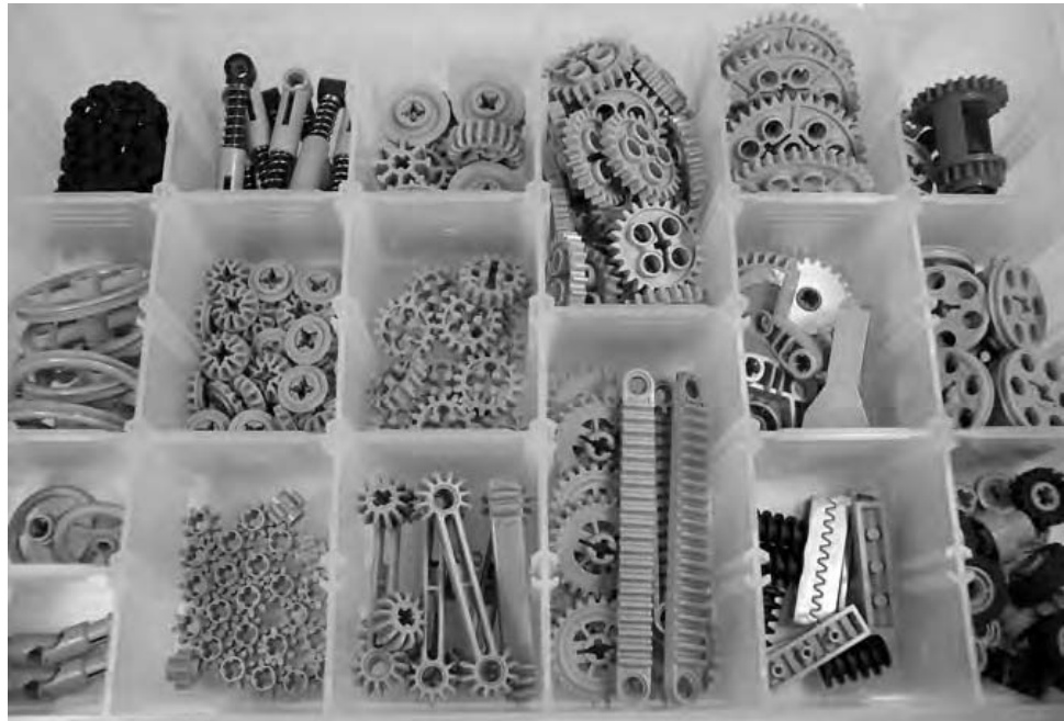
Figure 12-7: Tackle box–style containers offer efficient and organized storage for smaller pieces.
You’ll often find these types of boxes in the fishing tackle aisle or sometimes in the craft section of your favorite store. The great thing about them is that they very often have small dividers that allow you to configure the compartments into a variety of sizes and shapes. This enables you to customize the layout of each box to the parts you wish to put in it. This is what makes sure you get the best usage out of each container.
Reuse Containers You May Already Have: Tubs and Buckets
Perhaps you find that you are accumulating large quantities of basic bricks, plates, or slopes and you decide that another size of container is apt to be more useful. Before you go buy any more, remember that you may already have them on hand. If you’ve bought, or plan to buy, any assorted buckets or tubs from LEGO (they are typically offered in different forms every year or two), then you will have perfect storage containers sitting right in front of you. Figure 12-8 shows the difference between a tub and a bucket.
Figure 12-8: The taller square container on the right is a bucket. The wider, but slightly shorter, container on the left is a tub.
A large LEGO tub (shown on the left in Figure 12-8) can hold many times more bricks than it comes with when you buy it. Simply by dumping in loose bricks, I have found that a tub can hold 600 to 800 bricks at a minimum.
An average-sized LEGO bucket (shown on the right in Figure 12-8) can hold between 300 and bricks. However these containers don’t always store as nicely as the tubs.
These storage solutions serve an obvious purpose for certain elements that you have, or will eventually acquire, in larger quantities.
Even in the early stages of building your collection, you may want to revisit the examples earlier in this chapter to see how best to fill these handy boxes. For instance, you may have only half a container each of basic white and black bricks, but you may not have an empty tub for each color. Why not take these two diametrically opposed colors and let them share one tub? Here are some examples of colors that might share a tub well:
Black and white Red and light gray Blue and yellow Dark gray and orange Green and yellow Blue and white Yellow and black White and red
And so on. Actually, any combination can work so long as you, the builder, can easily tell the difference between them. For instance, putting green and blue in the same tub might, for some, be a bad idea since under less-than-perfect lighting, they might look similar.
By storing two colors in a single tub, you are maximizing the potential storage of that container and, in turn, lessening the amount of space your containers will take up. For some builders, the amount of space in their home that can be devoted to LEGO (both storage and building) may be limited. In that case, there’s no sense having a tub capable of holding hundreds of bricks sitting on a shelf only one-sixth full.
Deep Storage: Taking Care of Larger Quantities
For some builders, even large LEGO tubs may not suffice when it comes to the overflow, or bulk brick, side of their collection. There are those who eventually acquire massive quantities of basic bricks. For them, a single color might occupy five, ten, or even more standard LEGO tubs. In these cases, a better solution may be the large, chest-style storage containers—once again available in either brand-name or no-name varieties. As with the leftover-style boxes, the chest-sized versions range in size, thought not as much in shape. They may hold 15, 20, or even 30 gallons worth of bricks. They are effective for deep storage of certain elements.
Deep storage is that realm where you keep these large-volume containers filled with bricks that you might only use when you’re working on large-scale projects. This might mean that most of the time, these chest-style boxes are in storage somewhere, possibly away from the rest of your collection. They might be in a basement, a cold storage area, or perhaps even at the home of a relative if your own home lacks the room to keep them handy. This contrasts with all of the other containers you’ve looked at, most of which are generally not that far from where you want to set up to do your building and are, for the most part, easily accessible. It may require a bit of planning to retrieve the contents of deep storage containers so that you can have them on hand at the time they, or rather their contents, are needed.
Setting Up a Building Area
At the end of all this sorting and storing, you still need to conquer the most important task of all: building something. If you’re like me, at some point in your life building with LEGO bricks was no more complicated than plopping yourself down on the floor and digging through your boxes of pieces. But now, having reached the stage where you’ve sorted and more efficiently stored your elements, you may also want to set up an area where you can build models and perhaps even leave bricks out between building sessions. As well, you have probably already realized that keeping most of your pieces in large storage containers, either on a shelf or in a closet somewhere, makes it more difficult to just sit down and create a model. That’s the main reason most builders eventually set up a specific area for their LEGO hobby.
A building area does not need to be an entire room; in fact, it doesn’t even need to be an entire table! You can make good use out of just about any amount of space that you can set aside for your hobby. Figure 12-9 shows a building table that’s not even three feet wide, but it serves the purpose nonetheless.
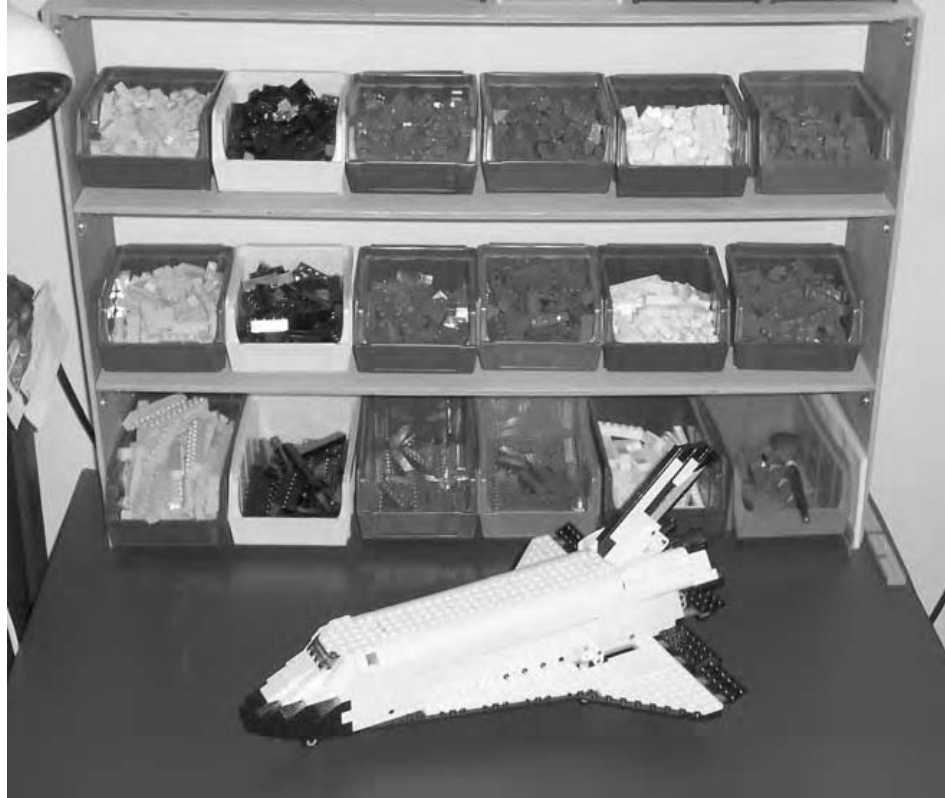
Figure 12-9: Your LEGO building area doesn’t need to be fancy or large. It only needs to be a place where you can work effectively.
First, and most obviously, you need to decide how much space you’ve got to work with. Maybe you’re lucky enough to have a small spare bedroom available, or perhaps a corner of a basement that you can call your own. On the other hand, your LEGO building area might be just an area under a window or along one wall of a spare room. Or, you may have to share a large table with someone else’s hobby. No matter what space you find yourself dealing with, the basic ideas behind setting up your workshop are the same.
-
Decide which LEGO elements are most important to the style of building you do. Maybe you want lots of gray and brown elements for building castles. Or perhaps you want most of your plates handy because you like to work on sculpture or mosaics. Or perhaps you want several common colors and sizes of basic elements available because you can never decide what you’re going to build next.
-
Decide how much of your work area you want to set aside for keeping the elements from step 1 close at hand. Remember, it’s great to be surrounded by thousands of pieces of LEGO, but if you’re only left with one or two square feet of building space, then you’re not going to enjoy yourself very much.
-
Find storage bins or containers that are suitable based on the decisions made in both step 1 and step 2. These may be small, open-front sorting bins (as in Figure 12-9), or they may storage units that feature lots of small drawers (as in Figure 12-10) in which you can keep your most needed bricks.
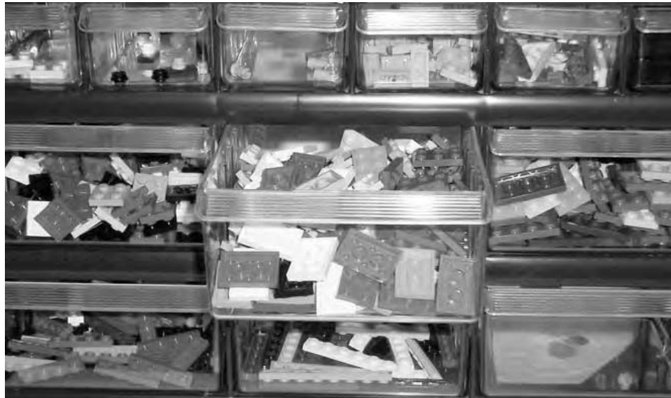
Figure 12-10: Sets of small plastic drawers offer great organization solutions that allow you to see your bricks from the front.
To make your building area most effective, you should also give at least some consideration to the following:
Lighting
If at all possible, try to illuminate your building table/area with lights that give off simulated natural daylight. These are a bit more expensive than normal light bulbs, but they offer you a better view of all your colorful LEGO pieces.
Chair
Assuming you are going to sit at your table (and you may not), you will want to get the most suitable seat you can find. This may be a swiveling, office-type chair or nothing more than a simple stool with a backrest. The point is that you are comfortable during your building sessions.
Atmosphere
This can be anything from the overall lighting of the room (sunlight vs. artificial light) to whatever other things you bring into it (for example, is this room strictly for LEGO or does it share space with your other hobbies?). As with the chair, this is all about making yourself comfortable. If you set up a huge LEGO table in the darkest corner of a damp, musty basement, you may not be as inspired as you would be if you picked a smaller space in an upstairs spare bedroom that has a good-sized window.
In addition, think about having the ability to play some music when you build; that can also create an environment that’s more suitable for your creative endeavors.
As with the decisions about how to sort and what to use for storage, the decisions about setting up your work area will be a mix of different answers. Not every solution noted here will work for you, but parts of one or more may work very well. Adapt your work area to your style of building, and your collection and you can’t go wrong.
Review: Unique Solutions for Every Builder
Early on in this chapter, I brought up the question that many builders ask, “Should I sort by color or by shape?” I think you can see, based on the many different solutions provided throughout the chapter, that the answer is completely dependent on you, your LEGO bricks, and your needs. No one answer is completely correct, and you may need to revisit a solution that works for you now as your collection expands or as your building style changes. Experimenting with and refining how you store and sort your bricks is a great addition to an already fun hobby. Resorting bricks, from time to time, is a good way to remind yourself of what elements you have available. Seeing a particular type or color of piece move from a small box to a larger storage container is a rewarding way of watching your collection grow along with your involvement in LEGO building.
13
M A K I N G A N D U S I N G T O O L S F O R L E G O P R O J E C T S
For many hobbies, you need some type of tool or combination of tools to work with the basic materials. When you build a car or an airplane from a plastic model kit, you need to use things like glue, paint, and perhaps even a knife to complete the project. To assemble models using the Meccano construction system or similar things out of Erector, you need screwdrivers and wrenches to tighten nuts and bolts.
One thing that has always made LEGO bricks easy to use is the fact that they require no tools to connect pieces together. Does that mean you can’t use tools? Not at all. In some cases, you may find it useful to add some small implements to your building environment. One of the very simplest of LEGO tools is little more than a standard brick or plate that can be used to measure other LEGO pieces—most often Technic axles.
As you’re building a model from an official LEGO set, you may find an image within the instructions that looks something like Figure 13-1.
Figure 13-1: This illustration tells you that you need two axles that are six studs long each.
As you can see, there are (usually) two numbers next to the picture of a Technic axle. The number with the letter X in front of it represents how many of that piece you need to use in this step of the instructions. The other number, with no letter next to it, indicates how long the axle should be. The length is measured in studs. Figuring out if you’ve got the right piece is easy—simply use a LEGO brick as your measuring tool as shown in Figure 13-2.
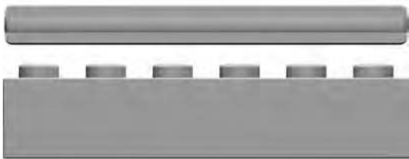
Figure 13-2: It’s easy to see that this axle is six studs long.
Using the brick, you can quickly confirm the length of the axle. This allows LEGO to manufacture the axles without worrying about any identifying marks. Although it may not seem very high tech, using a LEGO piece as a measuring device is using a tool nonetheless. This is a simple, yet elegant, solution, and one that has always struck me as another example of making something no more complicated than it needs to be.
There are also tools that can be made from … you guessed it, other LEGO pieces!
Presser Tool
One item that always sits on my building table is a presser tool; I find this useful when I’m working with small elements, especially in tight corners. The presser tool is handy for those times when you need to push down on a small tile, plate, or maybe a panel in a recessed corner or one that is between other elements where your fingertip just can’t reach. This tool is simple to build and is something you may wish to leave together so that it is always available when you need it. The pieces used to create this tool are shown in Figure 13-3.
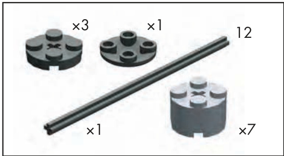
Figure 13-3: Bill of Materials for the presser tool
Actually assembling the tool is quite simple. Figure 13-4 shows how the cylinder bricks and plates slide onto the axle. You can use any combination of these elements to create your own customized patterns and color schemes.
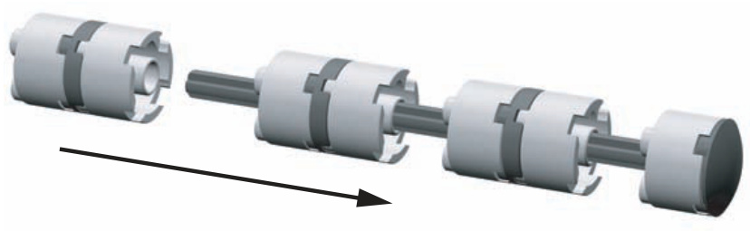
Figure 13-4: Assembly instructions for the presser tool
The inverted cylinder tile shown on the right side of Figures 13-4 and 13-5 forms the end of the tool giving it a nice, rounded look and feel.
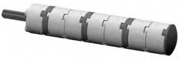
Figure 13-5: Ready to press!
In Figure 13-6, you can see the tool being used to seat a stubborn plate. You can loosely align the part in question, and then, using the presser tool, gently apply a downward force that helps set the piece in place.

Figure 13-6: The presser tool in action. The plate is dropped in and then pressed into its final spot using the tool.
The Ruler
Simplicity, as you’ve already seen, often provides for the best solutions.
You can use a ruler made of LEGO to measure distances between pieces of large models. For instance, perhaps you’re laying down the foundation for a large LEGO house. You can use the ruler to check the distances between the walls. Or, when you’re working on a sculpture, you can use it to check proportions of different parts of the model.
In the case of making your own ruler out of LEGO, it couldn’t be much simpler. Figure 13-7 shows you the Bill of Materials for this tool.
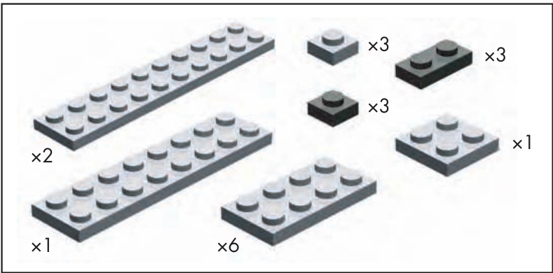
Figure 13-7: Bill of Materials for the ruler
The construction of this little project is almost self-explanatory. Any colors can be used, as long at the and markers are different than the reset of the elements, as you see in Figure 13-8.
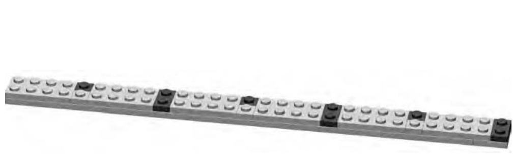
Figure 13-8: The completed ruler
The bottom layer of our LEGO ruler is made up of a , a couple of ’s, and a . The remainder of the plates go on the top layer to form the patterns shown in Figure 13-8. Measuring is just a matter of looking at the contrasting colored plates. The first dark represents 5 studs in length, the first dark indicates 10 studs, and so on. The ruler shown here can measure something up to 30 studs long.
Pin Stand Tool
In some of the official LEGO sets you may own, and eventually in some of your own original models, you may find situations where Technic pins, axles, and so on are inserted into various other elements. Sometimes getting these pieces out simply requires using another longer axle to give the piece a bit of a push from one side so that you can then grasp it in your fingers.
For other part combinations, perhaps ones in which you want to apply a bit more force to the stubborn piece, you might want to build yourself something to help. No normal combinations of LEGO elements should ever become fully and permanently stuck, but from time to time, two pieces find a snug fit that can be difficult to undo.
The pin stand tool itself can sit on your building table. You can then push a part down onto it from above. The parts you’ll need to build one of these are shown in Figure 13-9.
Figure 13-9: Bill of Materials for the pin stand tool
The instructions are easy to follow and the result is a small, but useful, tool that can sit nearby until you need it. To make your own version, simply follow steps 1 through 6 in Figure 13-10.
Figure 13-10: Instructions for building your own pin stand tool
With the tool sitting firmly on the table, or even resting on the floor, you can use both hands to center a part over it and push down until the piece is forced out. Figure 13-11 shows how simple it is to use this tool.
Figure 13-11: Pin stand tool in action. Align parts over the axle sticking up from the tool. Push down, and the small axle is pushed out of the Technic brick.
Brick Separator
Sooner or later you’re going to want to take one of your LEGO creations apart, whether it’s an official set that you built out of the box and put on a shelf for a few months, or a robot that you built last weekend. Eventually you’re going to want to reuse the pieces contained in it.
Although there’s nothing wrong with displaying your work, there is also a great deal to be gained by taking advantage of one of the other great qualities of the LEGO system—its reusability. Any piece can connect to almost any other piece. Working out all of these arrangements is part of what makes exploring and using the system so satisfying.
Now that you know it’s okay to take that model apart, what are you waiting for? Just start by pulling off large sections of bricks, breaking those down into smaller chunks, and finally separating individual bricks from one another. At some point, however, you are very likely to come across two or more pieces that are stuck together so tightly that you can’t pry them apart or even get a fingernail between them. Often these will be two small plates that are proving just how well the stud and tube mechanism works. Despite their best efforts to stay together, it is almost certain you’ll want to separate them. Let’s look at how best to do that.
In some official LEGO sets, and in some assorted tubs of bricks, you’ll find a rather odd looking piece of plastic (Figure 13-12). It isn’t quite a brick, but it does have some studs on it. It’s a brick separator.

Figure 13-12: The brick separator—a tool for builders of all skill levels
If you haven’t got one of these little tools, you may want to consider buying one. Better yet, you may want to consider buying two since they work well in pairs. If you haven’t found one in a LEGO set, you can normally purchase them directly from the LEGO company’s Shop at Home service, http://shop.lego.com. Look for item .
Brick separators sell for a couple of dollars each. They will save you much more than that in dental fees by helping you separate bricks and plates without resorting to yanking them apart with your teeth.
Take, for example, two plates stacked neatly together. They’ve been part of a model for months, and now they’re stuck together and won’t budge. Start by taking one of your brick separators in one hand; then place the stacked plates studs down on top of it. Then bring the second separator down from above; this creates something that looks like the handles of a pair of pliers (see Figure 13-13). And, like the handles of a pair of pliers, you want to squeeze the two separators together. With very little effort and not much movement, you should find that the two plates begin to disconnect at the edge facing away from the brick separator tools. The forces you are applying— along the top surface of the upper plate and along the bottom surface of the lower plate—quickly create a gap at one edge of the two plates that generally allows the two pieces to separate from each other.
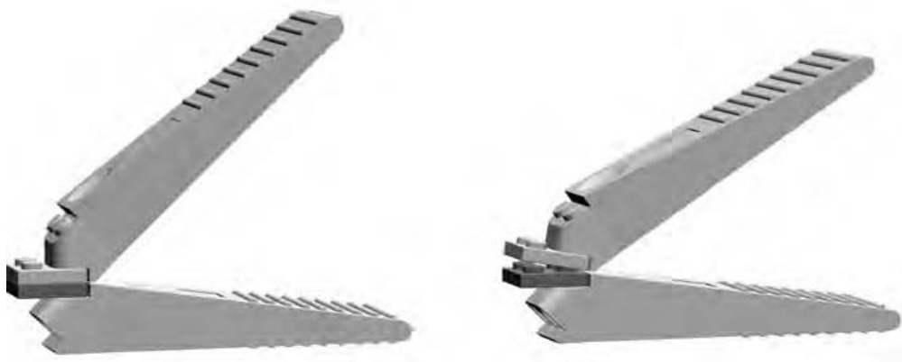
Figure 13-13: Two brick separators working to take apart two plates. Gently squeezing the two handles is usually enough to quickly separate even the most stubborn pieces.
Perhaps your problem isn’t two small parts stuck together, but rather one small part firmly affixed to a larger one. Take the case of a plate stuck in the middle of a plate, as shown in Figure 13-14.
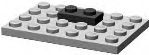
Figure 13-14: Sooner or later you’ll find yourself faced with the task of trying to remove a like the one shown here, from the middle of a much larger piece.
A single brick separator can be of great use here; it can simply apply a bit of leverage so you can free the little piece. In Figure 13-15, I’ve included a close-up shot that shows the separator working its magic.
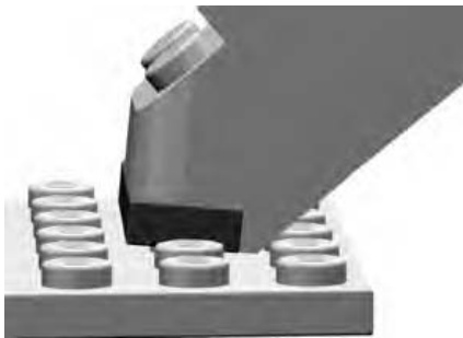
Figure 13-15: The brick separator’s unique design allows it to get close to the plate and then lever it away from the larger plate beneath it.
Of course, it goes without saying that you can also use these separation techniques when you are constructing a new model for those times you put two pieces together and then quickly change your mind.
Also remember that not having a brick separator doesn’t mean stuck pieces have to remain like that forever. Take a look at Figure 13-16 for another example of how to separate such pieces. This time, I’m using two plates. Because the plates are so small, it’s often hard to use your fingers to separate them. Instead of scratching away with your fingernails at the joint between them, try placing a brick on the top and bottom of the plate combination.
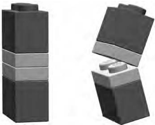
Figure 13-16: bricks on top and bottom of two plates. This easy solution uses pieces you already have.
The bricks now give you enough leverage to cause a small separation between the plates. This is very similar to how the brick separator works; the gap that forms is usually enough to allow you to then separate the plates completely.
You can also use a brick instead of the separator in the other example I noted earlier—the one where you have a small plate stuck in the middle of a larger plate. To make this work, put the brick on top of the plate (as demonstrated in Figure 13-17), and gently apply downward pressure as you tilt the brick toward the surface of the larger plate. If you do this without lifting up on the brick, you should find that the plate loosens sufficiently from the studs of the plate.
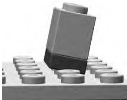
Figure 13-17: Here a standard brick is being substituted for a brick separator.
Non-LEGO Tools
I mentioned earlier that some of the tools we’d talk about in this chapter are made from LEGO, but that must mean some are not. The ones that are not might be things you already own; you just haven’t put them to use in LEGO building yet.
An example is a simple ruler. You may wish to measure part of your model, in real terms, inches or centimeters, especially if you are dealing with building something to a particular scale. We talked about scale at length in Chapter 3, so this next example should be easy to follow.
Suppose you are building a model of your favorite die cast metal car. You’ve measured the wheels on the real car and they are almost exactly onehalf the size of the smallest wheels you have in your LEGO collection. So you can build a LEGO model, using those wheels and based on that car, so it is twice the scale of the die cast car. (You know from further discussion of scale in Chapter 5 that this is a 2:1 scale model.) That means that everything you put on the car (roof, hood, doors, and so on) should also be twice as long and wide as the real thing. By using just an ordinary ruler, you achieve the result you are hoping for. Once again, tools don’t have to be complicated to be extremely effective.
A basic protractor (Figure 13-18) may also be handy from time to time, especially when you are trying to replicate things like large, arched structures or the roof of a building. (I talked about creating simulated arches using inverted slopes, near the end of Chapter 3.) If you are able to find a picture of the thing you are building, or if you can take one of your own, you can then use the photo as a reference document. Hold the protractor up to the arch or shape you want to re-create to find out the angle at which it curves or rises. Then, as you build the LEGO version, use the protractor again to see that your angles match those of the building that is the inspiration.
Both the ruler and the protractor aren’t really so much tools that you use to build the model as they are devices you use to transfer measurements and ideas from the original source material to your own work.
If you’re building a really large model involving a lot of bricks (perhaps a castle or a tall tower) you may want to think about getting a nonmarking rubber mallet. These are available at hardware or home improvement stores and probably have an off-white colored head. That head is important; it’s the part you don’t want to be leaving marks on your bricks. You will want to stay away from the black rubber mallets for this reason. To use this tool, simply set the bricks down in the way they are to be connected. Give them enough of a downward push with your fingers so that you know that the studs are matched up. Then gently (keyw ) tap them into place with the mallet. This isn’t so much a technique that will improve your building skills as it is one that might save some skin from being worn off your fingertips during long construction sessions.
Figure 13-18: A protractor and a ruler—two basic measurement tools that can help you achieve accuracy in almost anything you build
Other Useful Items
Though not specifically used for building models, you may find a couple of other things handy to have on or around your building area. I’ve listed them below and then included a picture of them in Figure 13-19.
Pencil and paper
Nothing beats good old-fashioned pencil and paper when it comes to sketching out an idea for a model or maybe writing down a list of parts you need to make it. If you’re sketching out plans for a model, you might want to use some of the Design Grids discussed in Appendix B of this book, or you may just want to draw freehand on some plain paper.
Calculator
You may find times when your brain just needs some help. This could be when you have to figure out a particular scale (as we discussed in Chapters 3, 4, 5, and 6), or it might just be when you want to make some rough calculations about how many bricks you’ll need for a particular project.
Paintbrush
If you’re going to use a paintbrush, preferably use one that’s never seen paint before. Look for one that is an inch or perhaps an inch and half wide. These are great for dusting models on display or partly built models after they have been sitting on your build table for a few days.
Small zip-closure bags
These are useful for storing small parts either during a build or after you’ve taken a model apart.

Figure 13-19: Some items you might find useful to have in or around your work area
Review: The Right Tools for the Job
The most important lesson to take from this chapter is to simply surround yourself with the tools, of any description, that help you build as easily as possible. They might include devices made from LEGO that help you build or take apart models more easily, or they might be other tools or objects that help you organize your thoughts and make plans to build models of your own design. Use only the tools you’re comfortable with, but use them freely. They will add enjoyment to your building sessions and, in turn, enhance your enjoyment of the hobby itself.
A B R I C K O P E D I A
The LEGO system is made up of thousands of elements. You’ve already seen many of them used and/or described throughout this book. Some are different sizes of the same type of piece (for example and are two different sizes of standard bricks), whereas others are exactly the same size but have different decorations or patterns printed on them. To catalog every piece in the system would require an entire book. However, at the same time, it’s useful to try to capture a sense of the various sizes, shapes, and configurations of pieces that exist. To that end, I have included illustrations of nearly 300 elements in this Brickopedia. They cover the range from basic bricks, slopes, and plates, to specialized elements, arches, and even a number of decorative elements.
I have categorized the Brickopedia from the perspective of building with LEGO pieces. As a result, I suggest that you do not use the Brickopedia to plan purchases of LEGO pieces from any type of store either online or at a real location; its categories and terminology may not match. Also, this catalog is not suitable as a device with which to record the contents of official
LEGO sets because they may contain specialty parts I have not listed here. In other words, some of the categories and descriptions used here are unique to this text.
Instead, my hope is that this Brickopedia is a tool that you can use (most specifically offline, without the use of a computer) to help categorize, organize, and utilize your most common and most useful elements. As noted, this does not cover the entire spectrum of available LEGO pieces. Rather, it focuses exclusively on standard, common, and highly reusable elements, thus helping you acquire a core knowledge of the LEGO system and its most important aspects.
Brickopedia Breakdown
Each category has a separate entry for each element that contains several pieces of information. The Brickopedia notation system is shown in Figure A-1.
Figure A-1: A sample Brickopedia entry
This information is not intended to value the parts, but only to hint at why you may or may not have certain pieces in your own collection.
I have kept the categories and subcategories lean and have made every attempt to use titles that suggest the nature of the pieces. Where possible, I have cataloged similar parts together to show their relationship. For example, I show standard and inverted slopes of the same size on the same page. This is different than many other categorization systems used for LEGO elements.
The Brickopedia divides LEGO elements into several broad categories; within each of these areas are subcategories that help refine the way pieces are classified (see Table A-1). The following tables (Tables A-2 through A-11) describe the major categories and subcategories. This information may be useful when you are sorting and storing your LEGO pieces and also when you are building with them. It may also give you a better sense of how the whole system works together, one part at a time.
Table A-1: LEGO Elements Categories and Subcategories
| Category | Subcategory | Description |
| Bricks | Standard | Rectangular sides, same height as a lxl brick. |
| Adapted | Irregular sides/shape or taller than a standard 1xl. | |
| Plates | Standard | Square or rectangular shape, same height as a 1x1 plate. |
| Adapted | Irregular sides/shape."Quarter cut" or "diamond cut" describe pieces that can be put together to form a circle or a diamond shape, respectively. | |
| Bow | One edge has symmetrical angles cut away whereas the opposite edge is straight or indented in the center. | |
| Wing | Come in left and right varieties, shaped like airplane wings. | |
| Slopes | Standard | The angled face is generally on the top portion of the element. |
| Inverted | The angled face is generally on the underside of the element. | |
| Peaks | Two or more angled faces meet at the top of the element. When in place, there are no exposed studs. | |
| Compound | Two or more flat-angled faces. | |
| Curved Junctions | Angled faces have a curve. Elements that have studs on their sides or have a | |
| Specialized Elements | portion of themselves that is perpendicular to another part. These pieces allow you to make a bend or a change in shape in a model where they create a junction of two or more pieces. | |
| Odd Face Hinges/Turntables | Elements that have one or more faces that are irregularly shaped, contoured, or textured. | |
| Pin-Enabled | Hinges are bricks or plates that meet at a flexible joint. Turntables allow attached elements to rotate. Bricks or plates with a Technic-style pin attached | |
| on one or more sides, the top, or the bottom, or elements capable of accepting a pin. | ||
| Wheels/Tires | Pieces that add motion to vehicles. | |
| Technic | Bricks | Pieces similar to standard bricks, but with axle holes running through them. |
| Plates | Identical to standard plates except that there are axle holes inserted between the studs. |
Table A-1: LEGO Elements Categories and Subcategories (continued)
| Category | Subcategory | Description |
| Technic, continued | Beams | Elements with axle holes running through them but lacking traditional studs. |
| Gears | Parts that function exactly as metal gears found in clocks, bicycles, and other real machines. | |
| Pins/Axles | Thin shafts used to mount gears and wheels onto Technic elements or connect Technic elements to each other. | |
| Bushings Couplers | Elements used to keep axles in place. | |
| Pieces that connect two or more axles, often providing a change of angle between the axles. | ||
| Arches | Standard Half Standard | A single piece that creates a complete arch shape. A piece that forms only half of the complete arch |
| Half Inverted | shape. Studs are on top as they are with the standard variety. | |
| A piece that forms only half of the complete arch shape. Tubes are on the bottom, and no studs are showing. The arch shape is effectively on top of the element. | ||
| Tiles and Panels | Tiles | Flat elements that are the same height as a plate but that have no exposed studs. |
| Panels | Thin elements that can create a division without occupying the same space as a full-width brick. | |
| Cylinders and Cones | Cylinders | Elements with a cylindrical shape that resembles a coffee can or a drum. |
| Cones | Elements shaped like upside-down ice cream cones. | |
| Baseplates | Brickplates | Baseplates that are one full brick in height and have dimensions of 8x16 studs or larger. |
| Waffleplates | Any of the thin baseplates with waffled undersides that do not accept studs. | |
| Decorative | Fences, Rails, and Rungs | Latticework or ladder-like elements that can be used as fences, grilles, hand rails, and so on. |
| Bars, Clips, and Elements with Handles | Bars are the diameter of aα minifig hand and the clips are any bricks or plates capable of holding them in place. Handled elements are those where the bar-sized portion is attached to an otherwise | |
| Foliage | standard piece. Any element representing or appearing to be | |
| Doors/Windows | flowers, trees, shrubs, or any other greenery. Self-explanatory. |
| Descriptor: 1x1 | Notes: This part is the basis of the LEGO system as laid out in this book. Measurements and categorization of | |
| Subcategory: Standard | existence. Just don't step on it barefoot | |
| Part #: 3005 | in the dark! [1958] | |
| Descriptor: 1x2 | Notes: The most common part in the entire system, having been used in more than 3,OOO different official sets. | |
| Subcategory: Standard | Mosaics, sculptures, minifig scale buildings, and just about every other thing you build will probably include | |
| Part #: 3004 | some of these. [1958] | |
| Descriptor: 1x3 | Notes: Something of an oddball simply because of its uneven number of studs. | |
| Subcategory: Standard | However, never overlook three-stud- long parts, simply because not every model or structure is always an even | |
| Part #: 3622 | number of studs. [1969] | |
| Descriptor: 1x4 | Notes: Like its half-size cousin, the 1x2, this part is common and very | |
| Subcategory: Standard | effective in a variety of situations. On the list of most common parts, this one | |
| Part #: 3010 | shows up at number five. You should find lots of these in your collection. [1967] | |
| Descriptor: 1x6 | Notes: A short stretcher-style brick. Not | |
| Subcategory: Standard | as common as the lx4 but not rare either. Extremely useful for creating large sections of walls for minifig-scale | |
| Part #: 3009 | dwellings or the walls of macroscale bricks. [1958] | |
| Descriptor: 1x8 | Notes: A longer stretcher-style brick. | |
| Not as common as the 1x4 but not rare either. Like the lx6, it is very | ||
| Subcategory: Standard | useful for quickly extending walls of | |
| Part #: 3008 | minifig buildings. [1958] |
Table A-2: The Bricks Category (continued)
| Descriptor: 1x10 | Notes: A fairly new addition to the standard 1xN bricks. Not as common | |
| Subcategory: Standard | as the lx8 but not rare either. Longer walls become short work with a long | |
| Part #: 6111 | brick like this. [1993] | |
| Descriptor: 1x12 | Notes: The second longest lxN brick, because at the time of writing, a lx14 | |
| Subcategory: Standard | brick does not exist. Uncommon in smaller sets. It provides a huge overlap | |
| Part #: 6112 | for smaller bricks resulting in a stronger model. [1993] | |
| Descriptor: 1x16 | Notes: Not often found in smaller sets, | |
| Subcategory: Standard | but if you can get your hands on some, you'll probably find them useful as your | |
| Part #: 2465 | own projects grow more complicated. [1988] | |
| Descriptor: 2x2 | Notes: The "stubby" is another brick that is sometimes overlooked. Several | |
| Subcategory: Standard | 2xscaeed | |
| Part #: 3003 | numbers of larger bricks. It is also the third most common part in the LEGO system.[1958] | |
| Descriptor: 2x3 | Notes: As is true with the 1x3, this | |
| Subcategory: Standard | brick is far more functional than you might think. Time and again you'll run across situations requiring pieces of | |
| Part #: 3002 | unequal length. Two of them together equal a 2x6—obvious, but easy to | |
| Descriptor: 2x4 | forget. [1958] Notes: The characteristic 2x4 is often | |
| Subcategory: Standard | the first brick people think of when discussing LEGO pieces. Introduced | |
| Part #: 3001 | with the earliest bricks in 1958, it continues to be a core building element. You can never own too many | |
| of these. [1958] Notes: A midsized beam that seems to | ||
| Descriptor: 2x6 | ||
| expected it to be around from the | ||
| show up in a lot of assorted tubs and | ||
| buckets. Despite its rather common | ||
| Subcategory: Standard | ||
| length, it's interesting to note its late | ||
| arrival into the system. You might have | ||
| Part #: 2456 | ||
| beginning.[1990] |
Table A-2: The Bricks Category (continued)
| Descriptor: 2x8 | Notes: This beam-like brick has been around since the beginning. It was first | |
| Subcategory: Standard | seen in the late 195Os when the stud and tube connection mechanism was | |
| Part #: 3007 | first patented. [1958] | |
| Descriptor: 2x10 | Notes: Another one of the original elements that first helped define the | |
| Subcategory: Standard | modern LEGO system of building. Useful for bracing large models or for | |
| Part #: 3006 | finishing a wall above windows or doors.[1958] | |
| Descriptor: 4x6 | Notes: First seen in the mid-199Os but is more common in some sets released | |
| Subcategory: Standard | after the year 2000. One of only three standard bricks that are four studs | |
| Part #: 2356 | wide.[1995] | |
| Descriptor: 4x10 | Notes: Introduced the same year as the | |
| Subcategory: Standard | 4x6 brick. Tends to show up in assorted tubs and buckets. [1995] | |
| Part #: 6212 | ||
| Descriptor: 4x12 | Notes: Seen a few times during the | |
| Subcategory: Standard | early 1980s but then not again routinely until the mid 1990s.A | |
| Part #: 4202 | relatively uncommon brick.[1981] | |
| Descriptor: 2x2 elbow | Notes: One of the so-called "elbow" | |
| pieces. Handy for shoring up the corner of a wall where columns of stacked pieces come together. | ||
| Subcategory: Adapted | Although it's the same pattern as the 4x4 elbow, the smaller version didn't | |
| Part #: 2357 | arrive until the late 1980s. [1987] | |
| Descriptor: 4x4 elbow | Notes: This brick is included simply as a comparison to the newer smaller 2x2 | |
| Subcategory: Adapted | elbow. The larger version has not been seen in regular sets for more than 35 | |
| Part #: 702 | years. Sounds like it's about time for it to reappear. What a handy element this would be. [1958] |
Table A-2: The Bricks Category (continued)
| Descriptor: 3x3 diamond cut | Notes: The descriptor lists this piece as being diamond cut because if you arrange four of them with their longest sides together, you get a somewhat diamond-shaped pattern. It's curious that this piece exists but that there isn't α 3x3 standard brick. [2001] | |
| Subcategory: Adapted | ||
| Part #: 30505 | ||
| Descriptor: 3x3 zig zag | Notes: Depending on which way this brick faces, it can provide texture because of its indented side. The reverse side gives a realistic bevel to a square corner where two walls meet. [1988] | |
| Subcategory: Adapted | ||
| Part #: 2462 | ||
| Descriptor: 2x3 left beveled | Notes: In some cases it's useful to look at two elements as a pair of similar pieces. That is certainly true when you're talking about these two beveled elements. Introduced in the mid-1990s, they can be used on cars, planes, spaceships, and the like to help contour the body providing greater | |
| Subcategory: Adapted | ||
| Part #: 6565 | ||
| Descriptor: 2x3 right beveledrealism than traditional bricks that | always meet at 9O-degree angles. Also available in the larger sizes 41767 and 41768. [1994] | |
| Subcategory: Adapted | ||
| Part #: 6564 | ||
| Descriptor: 2x4 left beveled | Notes: Although the 2x3 versions of these pieces were found in sets around 1994, the longer 2x4 versions shown here didn't arrive until 2OO2. As with virtually all parts of the LEGO system, they remain fully compatible and, in fact, the longer and shorter types work well together to create subtle shapes | |
| Subcategory: Adapted | ||
| Part #: 41768 | ||
| Descriptor: 2x4 right beveledand angles on your models.[2002] | ||
| Subcategory: Adapted | ||
| Part #: 41767 |
Table A-3: The Plates Category
| Descriptor: 1x1 | Notes: At one time LEGO referred to plates as "slim bricks," and you can see why—they are much shorter than | |
| Subcategory: Standard | regular bricks. Although the lx1 pictured here looks enormous, it's really not much bigger than the stud on | |
| Part #: 3024 | top of it. That makes it one of the smallest elements in the system.[1963] | |
| Descriptor: 1x2 | Notes: Ranked at number four when talking about the most common parts, this element also ranks highly when | |
| Subcategory: Standard | you're talking about the most useful parts. Don't let its small size fool you- | |
| Part #: 3023 | this part has a tremendous number of possibilities.[1963] Notes: As important and useful as the | |
| Descriptor: 1x3 | 1x3 standard brick. Pieces with odd numbers of studs are relatively | |
| Subcategory: Standard | uncommon. For instance, there is no 1x5- or 1x7-sized brick or plate. [1977] | |
| Part #: 3623 | Notes: Ranks at number nine on the list | |
| Descriptor: 1x4 | of most common parts. You can never have enough small-sized bricks or | |
| Subcategory: Standard | plates. Interestingly, this very common part was not one of the original | |
| Part #: 3710 | elements released in 1958.[1975] Notes: This piece may have arrived as | |
| Descriptor: 1x6 | early as l969 but was only seen in one set. It came into regular usage | |
| Subcategory: Standard | around 1977. It's amazing that such a common-sized piece wouldn't have been available right from the start. | |
| Part #: 3666 | [1977] | |
| Descriptor: 1x8 | Notes: Although available sooner than the 1x6, it is still interesting to note that this piece did not come into being until | |
| Subcategory: Standard | the early 197Os—more than α decade | |
| Part #: 3460 | after the launch of the modern system. [1972] |
Table A-3: The Plates Category (continued)
| Descriptor: 1x10 | Notes: If it were any longer, a lxN plate might start to have too much flexibility. Among the standard plates, | |
| Subcategory: Standard | ||
| Part #: 4477 | ||
| Descriptor: 2x2 | Notes: The plate version of the 2x2 stubby brick. This was one of a number of different plates to first appear in the early 1960s. [1963] | |
| Subcategory: Standard | ||
| Part #: 3022 | ||
| Descriptor: 2x3 | Notes: This one rounds out the list of basic elements with an odd number of studs on one side. Its usefulness will reveal itself as you advance to models | |
| Subcategory: Standard | ||
| Part #: 3021 | ||
| Descriptor: 2x4 | Notes: The plate version of the venerable 2x4 brick.A piece that has appeared in more than 2,5O0 different | |
| Subcategory: Standard | ||
| Part #: 3020 | ||
| Descriptor: 2x6 | Notes: Like its 2x6 brick counterpart, this element is used to bridge the gap between elements four studs and shorter and those that are eight studs | |
| Subcategory: Standard | ||
| Part #: 3795 | ||
| Descriptor: 2x8 | Notes: In the late 195Os and early 1960s, this part, among others, was available as one of the early parts packs. The availability of bulk parts | |
| Subcategory: Standard | ||
| Part #: 3034 | ||
| Descriptor: 2x10 | Notes: What about making a roof with a gentle slope by staggering a number of plates? You can do that, and when you do, this piece will come in handy | |
| Subcategory: Standard | ||
| Part #: 3832 |
Table A-3: The Plates Category (continued)
| Descriptor: 2x12 | Notes: Like the 3832, this piece helps build plate roofs among other things. And just like the 1x12 standard brick, this piece represents the second longest element in its category. In other words, | |
| Subcategory: Standard | ||
| Part #: 2445 there is no 2xl4 plate. Not sure why, but there isn't. [1987] | ||
| Descriptor: 2x16 | Notes: Sometimes there is a limit to just how long a piece can be. In this case, 2x16 is probably getting close to that limit. Like the lx1O plate, it's easy to imagine that anything longer than 2x16 might become too prone to | |
| Subcategory: Standard | ||
| Part #: 4282 | ||
| Descriptor: 4x4 | Notes: Although first introduced in 1969, this part was not seen in wide usage until 1973. It then began appearing in more official LEGO sets. [1969] | |
| Subcategory: Standard | ||
| Part #: 3031 | ||
| Descriptor: 4x6 | Notes: This piece was introduced in 1970 and was featured in a number of sets that first year. [1970] | |
| Subcategory: Standard | ||
| Part #: 3032 | Notes: The first year of the modern system featured only two larger plates. The first was this part and the second was the 6x8 plate.[1958] | |
| Descriptor: 4x8 | ||
| Subcategory: Standard Part #: 3035 | ||
| Descriptor: 4x10 | Notes: Nice to use when you want to build small minifig vehicles. You can simply attach wheels underneath and then build a passenger cab on top. | |
| Subcategory: Standard | ||
| Part #: 3030 [1969] | ||
| Descriptor: 4x12 | Notes: Long minifig vehicle or short section of a much larger wing of a much bigger aircraft? You decide. Also handy for filling in sections of floors for | |
| Subcategory: Standard | ||
| Part #: 3029 buildings.[1967] | ||
| Descriptor: 6x6 | Notes: Square plates start as small as the lx1. There are, of course, also | |
| Subcategory: Standard | 2x2 and 4x4 plates. For many years, the 6x6 was the largest of the perfectly | |
| Part #: 3958 | square plates. It is now joined by the 8x8 plate.[1978] |
Table A-3: The Plates Category (continued)
| Descriptor: 6x8 | Notes: The second of the two larger plates featured in sets released during the first full year of the modern system. [1958] | |
| Subcategory: Standard | ||
| Part #: 3036 | ||
| Descriptor: 6x10 | Notes: The late 1960s and early 1970s brought us several welcome additions to the 6xN-plate family. The next five parts were all released within 5 years of each other. [1971] | |
| Subcategory: Standard | ||
| Part #: 3033 | ||
| Descriptor: 6x12 | Notes: Another of the 6xN plates released between 1967 and 1975. [1967] | |
| Subcategory: Standard | ||
| Part #: 3028 | ||
| Descriptor: 6x14 | Notes: How strange that neither a 1x14 brick nor α 2x14 plate exist and | |
| Subcategory: Standard | e a organic enough to allow for these little | |
| Part #: 3456 | oddities and yet maintain its functional side at the same time. [1972] | |
| Descriptor: 6x16 | Notes: This plate is good for making | |
| Subcategory: Standard | train cars, fire trucks, and maybe even a piece of a roof made from plates | |
| Part #: 3027 | attached to hinges. [1967] | |
| Descriptor: 6x24 | Notes: Transport trucks, train cars, or even airplane wings all benefit from the availability of such a long,wide plate. [1967] | |
| Subcategory: Standard | ||
| Part #: 3026 | ||
| Descriptor: 8x8 | Notes: The largest of the perfectly square plates . . . for now. Is there a 10x10 plate on the horizon? You never know.[2001] | |
| Subcategory: Standard | ||
| Part #: 41539 | ||
| Descriptor: 2x2 elbow | Notes: Can't figure out how to tie together two lxN walls at a corner? | |
| Subcategory: Adapted | Maybe you've used the stacking technique and now need to hold two | |
| Part #: 2420 | sections together. The 2x2 elbow may be just what you need. [1987] |
Table A-3: The Plates Category (continued)
| Descriptor: 4x4 elbow | Notes: It's interesting to observe that although the 4x4 elbow is only 2 studs longer on each side than the 2x2, it has nine more studs. This gives it a greater surface area and allows it to hold together larger sections that meet at a vertical seam. [1991] | |
| Subcategory: Adapted | ||
| Part #: 2639 | ||
| Descriptor: 2x3 hitch | Notes: Can be built into a trailer hitch or used as a connection for Technic pins. Its curve matches a 2x2 cylindrical brick or plate.[1967] | |
| Subcategory: Adapted | ||
| Part #: 3176 | ||
| Descriptor: 3x3 quarter cut | Notes: Useful for rounding corners of wings, fenders, or even walls.[1999] | |
| Subcategory: Adapted | ||
| Part #: 30357 | ||
| Descriptor: 4x4 quarter cut | Notes: The only one of the three quarter-cut plates that forms a circle when you place four of them with their flat sides together. [2001] | |
| Subcategory: Adapted | ||
| Part #: 30565 | ||
| Descriptor: 6x6 quarter cut | Notes: This larger quarter-cut plate can create shapely balconies for minifig apartments or other structures where a large, rounded corner is an important | |
| Subcategory: Adapted | ||
| Part #: 6003 | ||
| feature.[1992] Descriptor: 3x3 diamond cut | Notes: Four of these pieces, placed with their longest sides together, form a multifaceted diamond shape. This is a pattern you might not always use—they are handy in pairs or alone-but it's | |
| Subcategory: Adapted | ||
| Part #: 2450 | ||
| Descriptor: 4x4 diamond cut | Notes: The diamond-cut family grew in 2001 with the addition of the 4x4 version. This piece is handy for helping to define complex shapes of wings on | |
| Subcategory: Adapted | ||
| Part #: 30503 planes and the like. [2001] |
Table A-3: The Plates Category (continued)
| Descriptor: 6x6 diamond cut | Notes: Observe the subtle difference between this diamond-cut element and the others in its subcategory. On the 6x6 version, there are two studs at each of the smallest pointed ends, rather than one, like on the other | |
| Subcategory: Adapted | ||
| Part #: 6106 | ||
| Descriptor: 8x8 diamond cut Notes: Big pieces can be beautiful too. This monster diamond-cut plate has | ||
| Subcategory: Adapted | been seen making up part of the wings of a space shuttle and it can certainly | |
| Part #: 30504 | add a similar shape to your models. [2001] | |
| Descriptor: 3x4 | Notes: This piece predates the 2x3 wing plates (43722 and 43723), but it | |
| Subcategory: Bow | forms essentially the same shape as a pair of them put together. The nose | |
| Part #: 4859 | portion of airplanes, helicopters, and so on are just a few uses for this little plate. [1985] | |
| Descriptor: 4x4 | Notes: As with the 4859 above, this piece is roughly the same shape as α | |
| pair of similarly sized wing plates. The biggest difference here is the 2x2- | ||
| Subcategory: Bow | cutout section into which you can put a minifig pilot's seat or an internal | |
| Part #: 43719 | substructure.[2003] Notes: Calling this a bow plate simply | |
| Descriptor: 3x6 | describes its shape; it doesn't limit its function. This piece could just as easily | |
| Subcategory: Bow | be the stern of a small ship or winglets on the sides of a small landing craft | |
| Part #: 2419 | launched from a larger spaceship. [1987] | |
| Descriptor: 4x6 | Notes: Although this is a bow plate by definition, its shape is also suggestive | |
| Subcategory: Bow | of the stern of a ship or perhaps a | |
| Part #: 32059 | small deck area jutting out from the side of such a vessel. [1998] |
Table A-3: The Plates Category (continued)
| Descriptor: 2x3 left | Notes: In the Brickopedia, I consider wing plates to be any plate elements that individually have the shape of a scalene triangle. In other words, each of their three sides is a different length. | |
| Subcategory: Wing | ||
| Part #: 43723 | ||
| Descriptor: 2x3 right | ||
| Subcategory: Wing | exact shape may not be perfectly aerodynamic, but as long as they give the sense of wings, they fit into this | |
| Part #: 43722 | category.[2002] Notes: These two pieces, when used | |
| Descriptor: 2x4 left | together, cover the same area as the 43719 bow plate. In fact, they cover | |
| Subcategory: Wing | slightly more, because they don't have the 2x2 area cut out from the inside. | |
| Part #: 41770 | The drawback of using them as a substitute is that you need to make sure | |
| Descriptor: 2x4 right | they are held together tightly by other elements. With the similarly shaped bow plate, the opposite is true-it can | |
| Subcategory: Wing | be used to hold other elements stable. [2001] | |
| Part #: 41769 | ||
| Descriptor: 4x4 left | Notes: I must admit a personal fondness for these stubby litle wings. | |
| Subcategory: Wing | They were part of a model that was released with the classic space sets back in the late 197Os, and it was | |
| Part #: 3936 | such a model that holds great memories for me. In that model, two | |
| Descriptor: 4x4 right | pairs of these pieces were used, with the second piece on each side fiting | |
| Subcategory: Wing | nicely into the notch that you see in each of the pieces. This creates an | |
| Part #: 3935 | unbroken edge that makes for great wing shapes. [1979] |
Table A-3: The Plates Category (continued)
| Descriptor: 4x8 left | Notes: This pair of wing plates were also seen in some of the early classic space sets. They have the same basic size and shape near the notch, but they then extend out twice as long as the 4x4's shown above. Of course, just because they're called "wing" plates | |
| Subcategory: Wing | ||
| Part #: 3933 | ||
| Descriptor: 4x8 right | doesn't mean that's the only role they can fill in your models. [1978] | |
| Subcategory: Wing | ||
| Part #: 3934 | ||
| Descriptor: 6x12 left | Notes: Classic space sets gave us two classic shaped wing plates, both of which are shown here. Twenty years later,sets based on a blockbuster movie franchise gave rise to what are sure to become classic plates in their | |
| Subcategory: Wing | ||
| Part #: 30355 | ||
| Descriptor: 6x12 right | own right. The 6xl2's shown here are long enough to be the only piece you need to form the entire wing for many minifig-scale ships. [1999] | |
| Subcategory: Wing | ||
| Part #: 30356 |
Table A-4: The Slopes Category
| Descriptor: 4x2 18 degree | Notes: One of the newest elements in the slope family is also one of the lowest. In fact, as of this writing, this is | |
| Subcategory: Standard Part #: 30363 | the only size of l8-degree slope currently available. lmagine entire roofs made from this slightly angled slope.[1999] | |
| Descriptor: 2x2 33 degree | Notes: The early 197Os ushered in a | |
| Subcategory: Peak | whole new series of sloped pieces- these were raked at 33 degrees as opposed to the 45-degree ones that | |
| preceded them. This particular example is a peak element that | ||
| Part #: 3300 | typically caps off a sloped roof. [1971] |
Table A-4: The Slopes Category (continued)
| Descriptor: 2x4 33 degree | Notes: The longer of the two 33- degree peaks. Although the 33-degree slopes are available in odd-numbered widths (one and three studs),the peaks come only in even-numbered lengths. | |
| Subcategory: Peak | ||
| Part #: 3299 | ||
| Descriptor: 3x1 33 degree | Notes: It wasn't until the early 1980s that 33-degree roofs with odd lengths became possible. However, it wasn't the 3xl slope shown here that gave us that opportunity; it was the 3x3 shown further along in the Brickopedia. [1982] | |
| Subcategory: Standard | ||
| Part #: 4286 | ||
| Descriptor: 3x1 33 degree | Notes: It was noted in Chapter 1 that many standard slopes have matching | |
| Subcategory: Inverted | inverted varieties. We see one here for the first time. The 3x1 inverted slope is a near mirror image of part 4286. | |
| Part #: 4287 | [1982] Notes: Among the first of the 33- degree slopes to be released in the early 197Os. Commonly referred to as | |
| Descriptor: 3x2 33 degree Subcategory: Standard | roof bricks, they are certainly used in that context. But as with most elements they are never limited to just one use. [1971] | |
| Part #: 3298 | ||
| Descriptor: 3x2 33 degree | Notes: The undersides of boats, pontoons,airplanes, and more all | |
| Subcategory: Inverted | benefit from inverted slopes like this. Although the 3xl slope was released in both standard and inverted styles in | |
| Part #: 3747 | the same year, the 3x2 standard had to wait 8 years for its inverted match. [1979] |
| Descriptor: 3x3 33 degree | Notes: Allowed roofs to be made at a 33-degree slant with odd numbers of studs for the first time.[1980] | |
| Subcategory: Standard | ||
| Part #: 4161 | ||
| Descriptor: 3x3 33 degree | Notes: Surely one of the more graceful looking slope elements. Low-angle, pagoda-style roofs just wouldn't be | |
| Subcategory: Outer Corner | complete without this corner piece. [1980] | |
| Part #: 3675 | ||
| Descriptor: 3x4 33 degree | Notes: As a kid, these were the parts I thought of as roof bricks. I had many of | |
| Subcategory: Standard | them in classic red. They remain an effective element to this day. [1971] | |
| Part #: 3297 | ||
| Descriptor: 2x1 45 degree | Notes: This peak can stand alone, capping off fences, castle walls,or | |
| Subcategory: Peak | even the backs of dinosaurs, or it can become part of the peak of a standard 45-degree roof. [1976] | |
| Part #: 3044 | ||
| Descriptor: 1x2 45 degree | Notes: A perfect companion for the 2x1 peak shown in the previous entry. | |
| Subcategory: End Peak | This piece can be used to finish off the end of a row of peak elements. [1965] | |
| Part #: 3048 | ||
| Descriptor: 1x2 45 degree | Notes: Used for those cases where one | |
| Subcategory: End Peak | peak meets another peak or a portion of sloped roof. The side facing front butts up against a piece like 3043 or against other 45-degree slopes. | |
| [1969] |
| Descriptor: 2x1 45 degree | Notes: Perhaps the only unusual thing about this element is that it was introduced to the system three years ifiat e common element that helps round out | |
| Subcategory: Standard | ||
| Part #: 3040 | ||
| Descriptor: 2x1 45 degree Notes: Useful for creating subtle inverted detail under the nose of a | ||
| Subcategory: Inverted | small airplane or the hip portion of a miniland figure; this piece can also help shape many small sculptures. [1976] | |
| Part #: 3665 | ||
| Descriptor: 2x2 45 degree | Notes: Standard 45-degree peak. It matches and uses the 3048 element to create a contoured roof. [1965] | |
| Subcategory: Peak | ||
| Part #: 3043 | ||
| Descriptor: 2x2 45 degree | Notes: One of the earliest slopes to be introduced to the modern system, although it's important to point out that these weren't there from the beginning. Roofs in the late l95Os and early 1960s had to depend primarily on | |
| Subcategory: Standard | ||
| Part #: 3039 | ||
| Descriptor: 2x2 45 degree | Notes: The inverted match to 3039. When you look down at the top of elements like this, you'll notice that part of the top is open and that some of the studs are actually hollow, like tubes | |
| Subcategory: Inverted |
| Descriptor: 2x2 45 degree | Notes: Another graceful slope element. Though this piece could also be considered a compound slope, it is probably best described as an outer corner because that's the portion of a roof it will most often become. [1965] | |
| Subcategory: Outer Corner Part #: 3045 | ||
| Descriptor: 2x2 45 degree | Notes: What happens when two sections of roof meet? Simple—you just need to join them together with an inside-corner slope like this. This is a unique piece in many ways because there is currently no similar element in | |
| Subcategory: Inner Corner | ||
| Part #: 3046 | ||
| Descriptor: 2x2 45 degree | Notes: You can find many uses for this piece, not the least of which is creating a turret effect near the top of a castle tower. [1984] | |
| Subcategory: Inverted Outer | ||
| Corner Part #: 3676 | ||
| Descriptor: 2x3 45 degree | Notes: You can never have too many elements with odd numbers of studs. This piece is no exception. [1965] | |
| Subcategory: Standard | ||
| Part #: 3038 | Notes: A peak element that's three | |
| Descriptor: 2x3 45 degree | studs long? Not common, but they do exist. [1965] | |
| Subcategory: Peak Part #: 3042 | ||
| Descriptor: 2x4 45 degree | Notes: If you're building a roof of any significant size, you'll need longer | |
| Subcategory: Standard | slopes like this one to cover the bulk of | |
| Part #: 3037 | the surface.[1965] |
| Descriptor: 2x2x2 65 degree Notes: Though this element was | originally released without a center tube inside,a newer version appeared in 2003 that did include this important feature. This is also currently the only | |
| Subcategory: Standard | piece that is raked at 65 degrees. [1978] | |
| Part #: 3678 | Descriptor: 2x2x2 75 degree Notes: No, it's not a dunce cap for | |
| square-headed people; it's an interesting and very steep peak element. This is useful for everything | ||
| Subcategory: Peak | from castle towers to Santa hats. Although the other 75-degree slopes are three bricks high, this one is only two.[1986] | |
| Notes: Yet another piece commonly found in castle walls, but also the | ||
| perfect angle for the rear end of a classic style of fire truck. [1984] | ||
| Subcategory: Standard | ||
| Part #: 4460 | Descriptor: 2xlx3 75 degree Notes: Currently the only 75-degree | |
| inverted element. Its interesting feature is that the entire face opposite the sloped side is hollow so that it accepts studs at a 90-degree angle. [1988] | ||
| Subcategory: Inverted | ||
| Part #: 2449 |
| Descriptor: 2x2x3 75 degree | Notes: A solid piece in both look and structure. This is perfect for the lower walls of any castle or any other building that requires a sturdy foundation. [1977] | |
| Subcategory: Standard | ||
| Part #: 3684 | ||
| Descriptor: 2x2x3 75 degree Notes: A perfect match for the 3684 and 4460. This one gives you the angles you need to create a corner. You can even use 75-degree slopes to | ||
| Subcategory: Outside Corner ski chalet.[1978] | create a very steep roof, perhaps for a | |
| Part #: 3685 | ||
| Descriptor: 1x3x2 | ||
| yet found its way into a large number of sets. Hopefully that will change as the years go by. This element perfectly Subcategory: Curved matches the curve of the 1x3x2 half- arch piece (6005) shown in the arches | ||
| Part #: 33243 | category.[2003] Notes: Another element that really has no equal in terms of shape. This | |
| Descriptor: 3x2 bullnose | ||
| Subcategory: Curved | ||
| vehicles.[1995] Part #: 6215 |
| Descriptor: 2x4 left 45 to 90 degree | Notes: In my mind, these two elements are some of the most interesting to be released in many years. They are unique in that they have the ability to act as intermediaries between standard bricks and 45-degree slopes. That is because one end of each of | |
| Subcategory: Curved | ||
| Part #: 43721 | ||
| Descriptor: 2x4 right 45 to 90 degree | degrees. Then, along its four-stud length, that 9O degrees transforms to 45 degrees, becoming one full stud wider at the base as it does. [2002] | |
| Subcategory: Curved | ||
| Part #: 43720 | ||
| Descriptor: 6x2 left | Notes: Spaceships, airplanes, and other flying machines all became more streamlined with the addition of this pair of pieces to the system. The compound shape—which has a curving slope from tip to studs and a matching curved side—provides a very sleek and realistic shape for traveling machines. [2002] | |
| Subcategory: Compound | ||
| Part #: 41748 | ||
| Descriptor: 6x2 right | ||
| Subcategory: Compound | ||
| Part #: 41747 | ||
| Descriptor: 6x2 left | Notes: The year 2002 was obviously an important one for new slopes; these two slopes and the four preceding them in this table all made their debut during that year. This pair of elements helps add contours to boats of all | |
| Subcategory: Compound Inverted | ||
| Part #: 41765 | ||
| Descriptor: 6x2 right | sizes, whether as parts of the bow or parts of pontoons to help keep it afloat. They can be used together, side by side,or separated by piece 500 (6x1 curved inverted) to make a wider profile.[2002] | |
| Subcategory: Compound Inverted |
Part #: 41764
| Deschpior:ox1 Part #: 464 | Subcategory: Curved | at times you may want something a little more delicate. These two pieces offer just such a quality. Given their shape,they obviously create a more rounded, and therefore a smoother, angle.[2002] |
| Descriptor: 6x1 | ||
| Subcategory: Curved Inverted Part #: 500 | ||
| Descriptor: 6x2 | Notes: Matching exactly the slope of part 464, the 6x2 version is also suited for nose cones, wings, and other models that require its gentle arch. [2003] | |
| Subcategory: Curved | ||
| Part #: 44126 | ||
| Descriptor: 4x4 original style Notes: This element is older than the | 6069 and is certainly somewhat boxier in the way that its sloped sides meet. [1985] | |
| Subcategory: Compound | ||
| Part #: 4858 | ||
| Descriptor: 4x4 new style | Notes: Sometimes new parts come along that make older versions look somewhat dated. Although the 6069 shown here isn't an exact replacement for the 4858, it certainly creates a more sporty projection.[1992] | |
| Subcategory: Compound | ||
| Part #: 6069 | ||
| Descriptor: 4x4 | Notes: Although released at the same time as the 4858 compound slope, this inverted element is a much closer match to the more modern-looking 6069 shown previously. [1985] | |
| Subcategory: Compound Inverted Part #: 4855 |
| Descriptor: 2x2 macaroni | Notes: Among the most beloved pieces ever produced. Its only real drawback is that it is often difficult or expensive to acquire in large quantities. Maybe | |
| Subcategory: Odd Face someday a bulk pack of these will be available in common colors.[1958] Part #: 3063 | ||
| Notes: It's tempting to think that this | ||
| Descriptor: 4x4 macaroni | piece could have been created anytime in the last 4O years, but for | |
| Subcategory: Odd Face | whatever reason, it took until 2004 for it to appear. An excellent companion | |
| Part #: 48092 | to the original 2x2 macaroni brick. [2004] Notes: The famed headlight brick | |
| Descriptor: 1x1 with indented stud on one side | shown here in two different views- from both the front and the back. Of course front and back are not always | |
| Subcategory: Junctions | important when you're using this piece because it can attach to other elements in a variety of ways. Similarly, it offers various options by which you can | |
| Part #: 4070 | attach other pieces to it. The indented stud on the side can become home to transparent 1x1 cylinder plates to | |
| Descriptor: 1x1 with indented stud on one side | create faux headlights. You can use a row of these to attach a 1xN element horizontally and, of course, the | |
| Subcategory: Junctions | opening in the back can accept a single stud of any kind.[1979] | |
| Part #: 4070 | ||
| Descriptor: lxl with studs on Notes: This piece was long awaited by two sides | many builders. It brings the usefulness of the headlight brick to another level | |
| Subcategory: Junctions | only two sides allows this piece to | |
| Part #: 47905 | become part of any wall. [2004] |
Table A-5: The Specialized Elements Category (continued)
| Descriptor: 1x1 with studs on all sides | Notes: Having been around much longer than the 47905 shown in the previous entry, this element is sometimes called the hydrant brick. | |
| Subcategory: Junctions | Although amazing in its design, it does have a drawback; often the studs you aren't using just get in the way. [1985] | |
| Part #: 4733 | ||
| Descriptor: 1x4 with studs onNotes: Although it may not be the most one side | elegant part, this piece just might be one of the most functional. It's small enough to build into almost any | |
| Subcategory: Junctions | structure, yet at the same time, it offers four horizontal studs onto which you | |
| Part #: 30414 | can then securely attach other pieces. [2000] | |
| Descriptor: 2x4x2 with studs on three sides | Notes: You might not need one of these pieces every day, but that shouldn't stop you from searching for new uses for such an unusual element. | |
| Subcategory: Junctions | This solid piece can form the core of junction substructures.[1990] | |
| Part #: 2434 | ||
| Descriptor: 2x4x2 with tubes Notes: The creation of the 2x4x2 with on sides | studs on all sides (part 2434) left an obvious opening for the opposite part. | |
| Subcategory: Junctions | Thus the 2x4x2 with tubes on two sides was born. Its rather industrial look earns it the nickname “engine | |
| Part #: 6061 | block."[1992] | |
| Descriptor: 1x2 single-stud offset plate | Notes: A tiny piece with one lowly stud might not seem that useful, but think | |
| Subcategory: Junctions | again.With this element, you can have parts of a model that are recessed one- | |
| half stud in depth offering greater subtlety to the shape and feel of your | ||
| Part #: 3794 | work. [1977] |
Table A-5: The Specialized Elements Category (continued)
| Descriptor: lx1 to 1x1 bracket | Notes: Need to change directions within a very small space? This is your part of choice. The hole on top is exactly one stud in diameter, and the area around it is exactly the height of a stud as well. [2002] | |
| Subcategory: Junctions | ||
| Part #: 554 | ||
| Descriptor: 1x2 to 2x2 bracket | ||
| Subcategory: Junctions | pieces into a vertical wall leaving the four-studded side exposed and available for attaching other parts. Although it's relatively new, this is likely to become a valuable member of the bender class of parts.[2002] | |
| Part #: 44728 | ||
| Descriptor: 2x2 to 2x2 bracket | Notes: This was one of the earliest parts to ever offer studs that were perpendicular to the base of the part. This gem showed up in some of the classic space-themed sets of the late 1970s. [1978] | |
| Subcategory: Junctions | ||
| Part #: 3956 | ||
| Descriptor: 1x2 to 1x4 bracket | Notes: Similar in many respects to part 44728. The difference is that the four oizoelsdasie Again, this part is useful when you're trying to attach something directly to a | |
| Subcategory: Junctions | ||
| Part #: 2436 | vertical wall. [1987] Notes: Odd Face was the name given to this subcategory because the “face" or front surface of these bricks is | |
| Descriptor: 1×2 log | ||
| Subcategory: Odd Face | something other than standard studs or just a smooth wall. The log brick is, of course, useful in brown, but gray versions are interesting too.[1996] | |
| Part #: 30136 |
Table A-5: The Specialized Elements Category (continued)
| Descriptor: 1x4 Log | Notes: The longer version of part 30136. What's unfortunate is that as of this writing, there isn't a lx1 log brick. However, you can sometimes | |
| Subcategory: Odd Face | ||
| Part #: 30137 | least some of the effect you're after. [1996] Notes: A unique piece in that the | |
| Descriptor: 1x2 grille | oddness of its face is different from front to back. Both sides can be described as grille-like. You can use these in groups or rows with similar faces exposed or, alternately, you can mix unlike faces for a great effect. You'll sometimes see these functions as | |
| Subcategory: Odd Face | ||
| Part #: 2877 | ||
| Descriptor: 1x2 grille (rear view) | ||
| Subcategory: Odd Face | [1986] | |
| Part #: 2877 | ||
| Descriptor: 1x2 and 1x2 | Notes: Although technically two pieces, this pair is almost always seen and used together.[1987/1987] | |
| Subcategory: Hinges | ||
| Part #: 2429/2430 | ||
| Descriptor: 1x2 and 1x2 brick | Notes: You can certainly use this pair of parts to create a wall section that swings away from the rest of a building, but you can also used it to create angled sections that don't move. | |
| Subcategory: Hinges | ||
| Part #: 3830/3831 | ||
| Descriptor: 1x2 brick | Notes: You can use this piece to give motion to things like spaceship cockpits or you can angle the studs forward and build the brick into a stationary wall. | |
| Subcategory: Hinges | ||
| Part #: 3937/3938 | Once the studs are exposed, you can use them to attach other elements. [1978/1978] |
Table A-5: The Specialized Elements Category (continued)
| Descriptor: 2x2 brick | Notes: We saw this pair of elements as part of the alternative section in Chapter 3. In that case, we used the larger top portion to help support the angled alternate roof. [1978/1991] | |
| Subcategory: Hinges | ||
| Part #: 3937/6134 | ||
| Descriptor: 2x5 plate | ||
| Subcategory: Hinges | Notes: A classic piece in many respects. This piece is sometimes used to attach things like fire truck ladders, | |
| but it is just as capable of being the hinge for wings on a quirky bird. [1967] | ||
| Part #: 3149 | ||
| Descriptor: 2x2 plate | Notes: A scaled-down version of the larger 4x4 turntable. This is only one plate high and can hide in many inconspicuous areas of a model. [1977] | |
| Subcategory: Turntables | ||
| Part #: 3680 | ||
| Descriptor: 4x4 brick | Notes: The part depicted here is actually the "modern" version of a similar element that was first produced back in l963. Earlier versions did not have the square baseplate seen here; | |
| Subcategory: Turntables | ||
| Part #: 3403 | rather, they were cylindrical all the way to the bottom. [1977] Notes: Momentarily I'll introduce you to the 1x4 channel-face brick. The | |
| Descriptor: 1x2 channel rail plate | ||
| Subcategory: Odd Face | piece shown here can be used to build a substructure that can then be slid into the lx4 channel-face element (part 2653) with great precision. Also available in a version that is eight studs | |
| Part #: 32028 | ||
| Descriptor: lx2 channel face Notes: This piece is sometimes used as | long. [1997] a purely decorative element when put together using the stacking technique. | |
| Subcategory: Odd Face [1981] |
Table A-5: The Specialized Elements Category (continued)
| Descriptor: lx4 channel face Notes: Although this can certainly be | decorative, it can also be quite useful for accepting substructures mounted on | |
| Subcategory: Odd Face Part #: 2653 | the 32028 channel rail plates.[1991] | |
| Descriptor: 1x2 pin face with one pin | Notes: So you've built a substructure on rail plates and are using the lx4 channel brick to mount it. Now you | |
| Subcategory: Pin-Enabled | need to lock it in place. lx2 bricks like the one shown here can mate up with | |
| Part #: 2458 | 1x2 Technic bricks, which are shown in the Technic category. [1988] | |
| Descriptor: lx2 pin face with two pins | Notes: The pin configuration on this piece matches exactly with any two | |
| Subcategory: Pin-Enabled | holes on any other Technic brick. Note that its pins are centered under the studs,unlike the 2548 above,whose | |
| Part #: 30526 | pin is located between the studs. [2000] | |
| Descriptor: 2x2 pin face | Notes: When you need a pin to be a secure part of a solid wall, reach for | |
| Subcategory: Pin-Enabled | this element. Building it into α 2xN wall gives you a sturdy pin onto which you can attach almost anything. | |
| Part #: 4730 | [1985] | |
| Descriptor: 2x2 pin top | Notes: This is perhaps one of those parts you might not need for the longest time, but when you do, you'll | |
| Subcategory: Pin-Enabled | be glad it exists. The same goes for the plate version of this part (2460). [1995] | |
Table A-5: The Specialized Elements Category (continued)
| Descriptor: 2x2 pin top plate Notes: Sure, this piece can be a place | to mount the rotors for a small helicopter, but it can be so much more. Check the description for the pin drop | |
| Subcategory: Pin-Enabled | ||
| Part #: 2460 | ||
| Descriptor: 2x2 pin drop plate | Notes: Here's what you do: First, build α Technic beam into the side of a model, a beam with three or more holes. Then, join together two or more | |
| Subcategory: Pin-Enabled | ||
| Part #: 2476 | ||
| Descriptor: Single drop hole plate | Notes: These pieces allow Technic pins or axles to attach below bricks or plates. Those pins or axles could carry gears, wheels, or other Technic bricks with similar holes. The 2444 piece is shown from the side under which is attached its only hole. The 2817is viewed from the side, showing both | |
| Subcategory: Axle Plate | ||
| Part #: 2444 | ||
| Descriptor: Double drop holeholes. [1987/1989] plate | ||
| Subcategory: Axle Plate | ||
| Part #: 2817 | ||
| Descriptor: 2x2 plate with | Notes: A compact model may still require motion.The wheel/tire set here is mounted on a tiny 2x2 plate that has slender pins sticking out each side. | |
| small wheels/tires Subcategory: Wheels/Tires | ||
| Part #: 4600/4624/3641 | ||
| Descriptor: 2x2 wide plate with slick tires | Notes: Are you creating a microsized street machine? Why not include some mean looking slicks? The plate in this figure sets the wheels out wider than the one shown in the previous entry. | |
| Subcategory: Wheels/Tires | ||
| Part #: 6157/6014/30028 |
Table A-5: The Specialized Elements Category (continued)
| Descriptor: 2x4 brick with medium wheels/tires | Notes: The wheels you see here (with the four studs showing) are sometimes referred to as Freestyle, named after the series of sets from which they originated. They spin freely on pins jutting out from the sides of the 2x4 | |
| Subcategory: Wheels/Tires | ||
| Part #: 6249/6248/3483 | ||
| Descriptor: Medium wheels with Technic axle holes | Notes: These wheels,with Technic axle holes, can find themselves used in a huge number of ways. Pop some Technic bricks on this axle, and you can mount the wheels on a car. Strip | |
| Subcategory: Wheels/Tires | ||
| Part #: 3482/3483 | ||
| pulleys. [1984/1985] | ||
| Descriptor: Brick separator | Notes: Did you know that the brick separator isn't just a tool, but it's also considered a part within the LEGO system? After all, it does have studs on | |
| Subcategory: n/a | ||
| top and the equivalent of tubes Part #: 6007 underneath. [1990] |
Table A-6: The Technic Category
| Descriptor: 1x1 with one axle hole | Notes: At first glance, this element might seem too tiny to be of much use, but don't let its compact size fool you. This just makes it easier to sneak it into an otherwise tight situation, which allows you to attach other Technic elements to it. [1993] | |
| Subcategory: Brick | ||
| Part #: 6541 | ||
| Descriptor: 1x2 with one | ||
| axle hole Subcategory: Brick | Notes: This piece was first introduced with the other original Technic elements back in 1977.Though it appears in a variety of colors every | |
| year, it's interesting to note that, since the beginning, at least one set each year has had the black version of this part in it. [1977] | ||
| Part #: 3700 |
| Descriptor: 1x2 keyhole | Notes: The keyhole brick is unique among the Technic elements, in that it effectively locks an axle in a certain position. You can then use that axle (or | |
| Part #: 32064 | axle/pin) to attach wheels, pulleys, or other moving parts. [1998] | |
| Descriptor: 1x2 with two | Notes: Even good ideas can sometimes take a while to see the light of day. | |
| Subcategory: Brick | Having one axle hole under each stud allows for different connections than those that are possible with other bricks where the holes are centered | |
| Part #: 32000 | between the studs. [1996] | |
| Descriptor: 1x4 | Notes: A common-sized Technic brick that has been incorporated into a wide variety of sets over the years. [1977] | |
| Subcategory: Brick | ||
| Part #: 3701 | ||
| Descriptor: 1x6 | Notes: Another common element that, like the lx4 version, has been seen in | |
| Subcategory: Brick | a large range of sets since first being produced back in the late 1970s. | |
| Part #: 3894 | [1978] | |
| Descriptor: 1x8 | Notes: This is perhaps one of the more | |
| commonly available lengths of the standard Technic bricks. It has | ||
| Subcategory: Brick | appeared in nearly 3OO different sets over the course of the last quarter | |
| Part #: 3702 | century. [1977] | |
| Descriptor: 1x10 | Notes: Though not introduced in the | |
| Subcategory: Brick | ||
| earliest years of the Technic elements, | ||
| this was an obvious size to add to the | ||
| list. [1985] | ||
| Part #: 2730 | ||
Table A-6: The Technic Category (continued)
| Descriptor: 1x12 | Notes: Most LEGO builders willtell you that you can never have too many LEGO pieces. And though the medium- | |
| Subcategory: Brick | length Technic bricks might not feel that different from each other, it's a good | |
| Part #: 3895 | bet that you'll want to collect lots of each size if you can. [1978] | |
| Descriptor: 1x14 | Notes: Although there is no standard 1x14 brick, there is an element of this | |
| Subcategory: Brick | length in the Technic series of parts. This piece is a relatively new addition | |
| Part #: 32018 | to the Technic family. [1997] | |
| Descriptor: 1x16 | Notes: The granddaddy of the standard Technic beams. These pieces | |
| Subcategory: Brick | are much sought after by builders of all skill levels, especially those working on | |
| Part #: 3703 | things like cranes or bridges. [1977] | |
| Descriptor: 2x4 | Notes: The invention of the LEGO Technic brick brought about the | |
| Subcategory: Plate | necessity of inventing a plate to go along with it. The 2x4 version was first | |
| introduced in 1977 and since then, there have only ever been three | ||
| Part #: 3709B | different sizes of this type of part. [1977] Notes: The second in the trio of | |
| Descriptor: 2x6 | standard Technic plates. The holes in the plates (centered between the studs) allow for axles to be positioned | |
| Subcategory: Plate | vertically, though the axles generally spin best when you steady them with a | |
| Part #: 32001 | second plate above or below the first. [1996] | |
| Descriptor: 2x8 | Notes: The longest standard Technic plate yet produced. Note that this version, like the 2x4, was first released | |
| Subcategory: Plate | in 1977. It's odd that the 2x6 (pictured in the previous entry) would have to | |
| Part #: 3738 | wait nearly 2O years to first see the light of day. [1977] |
| Descriptor: 1x3 | Notes: An interesting little piece with a single standard axle hole in the center surrounded on either side by plus-sign- shaped holes that are exactly the size | |
| Subcategory: Beam Half- Width | ||
| Part #: 6632 | ||
| Descriptor: 1x3 Notes: This is the smallest of the full- width pieces. Note that it is the same | ||
| Subcategory: Beam Full- Width | length as part 6632 but contains only rounded axle holes. Most of the straight full-width beams share this trait. [2000] | |
| Part #:32523 | ||
| Descriptor: 1x4 liftarm | Notes: This element represents one of the first of the studless liftarm style of pieces to be introduced. In its first year of production, this piece appeared only in a parts pack and not in a set that built any sort of model. [1987] | |
| Subcategory: Beam Half- Width | ||
| Part #: 2825 | ||
| Descriptor: 1x5 | Notes: The shortest of the half-width elements to feature only smooth axle holes. Contrast this to part 6632, which is shorter but also has holes that lock axles in place. [1997] | |
| Subcategory: Beam Half- Width | ||
| Part #: 32017 | ||
| Descriptor: 1x5 | Notes: This piece, like the other full- width beams, has only smooth axle holes throughout its length. These allow for pins and axles to rotate freely. For comparison, see part 32348,which also has holes that prevent axles from | |
| Subcategory: Beam Full- Width | ||
| Part #: 32316 | ||
| Descriptor: 1x6 | Notes: Like most of the other half-width straight beams, this part consists only of rounded pin/axle holes. [1998] | |
| Subcategory: Beam Half- Width |
Table A-6: The Technic Category (continued)
| Descriptor: 1x7 | Notes: The longest of the half-width sized pieces. As seen in Figure 9-6, these slender pieces help introduce rounded and gentler shapes to what might otherwise be boxy Technic | |
| Subcategory: Beam Half- Width | ||
| Part #: 32065 | ||
| Descriptor: lx7 single bend | Notes: Most of the bent beams share the common feature of having fixed- axle holes at each end and open holes in between that allow axles to rotate. [2000] | |
| Subcategory: Beam Full- Width | ||
| Part #: 32348 | ||
| Descriptor: 1x9 Notes: Like its longer cousin (the | ||
| Subcategory: Beam Full- | 1x15), this is not a piece that appears in large numbers in single sets.[2001] | |
| Width Part #: 120 | ||
| Descriptor: lx9 single bend | ||
| Subcategory: Beam Full- | Notes: This piece is identical to part 6629,other than the fact that the bend on this piece occurs at the third axle hole. [1999] | |
| Width Part #: 152 | ||
| Descriptor: 1x9 single bend | ||
| Notes: ldentical to part 1 52, other than Subcategory: Beam Full- | the fact that the bend on this piece occurs at the fourth axle hole.[1996] | |
| Width Part #: 6629 | ||
| Descriptor: 1x15 | Notes: The longest of the full-width beams currently available. These are not terribly common pieces and rarely show up in large quantities in any one | |
| Subcategory: Beam Full- Width |
| Descriptor: 1x11.5 double bend | Notes: I've always thought this part had the obvious resemblance to the forks on the front of a forklift vehicle. [1997] | |
| Subcategory: Beam Full- Width | ||
| Part #: 32009 | ||
| Descriptor: 2x4 single bend Notes: Proof that Technic beams come in all manner of variations. Note that | ||
| Subcategory: Beam Full- Width | this one has a 9O-degree bend near one end but that only one of its ends has the X-shaped axle opening. The remaining openings are pin-type holes. [1999] | |
| Part #: 32140 | ||
| Descriptor: 3x3 single bend | Notes: Ifind this element quite pleasing to the eye. It has a natural symmetry, and the openings (mostly of the locking axle type) give it the look of fancy metal work. Oh, and it's handy for building Technic models too![1998] | |
| Subcategory: Beam Half- Width | ||
| Part #: 32056 | ||
| Descriptor: 3x3 braced | ||
| Notes: Elements like this one and part 32250 combine the traditional square geometry of LEGO elements with more natural curved shapes. They are especially useful in small models where you want to achieve complex angles in small spaces. [2000] | ||
| Subcategory: Beam Half- Width | ||
| Part #: 32249 | ||
| Descriptor: 3x5 single bend | ||
| Notes: A simple variation of part 32140. Many of the elements in this category seem to be different combinations of length, hole type, and number of bends along their length. [2000] | ||
| Subcategory: Beam Full- Width |
| Descriptor: 3x5 braced | Notes: A long, more sloped version of part 32249. This one lends itself well to large-scale automobiles or flying machines. [2000] | |
| Subcategory: Beam Half- Width | ||
| Part #: 32250 | ||
| Descriptor: 8 tooth | Notes: Barely bigger than the axles on which it is mounted, this little gear is handy for so many things. It helps create the steering for the model in Figure 9-1 and helps with changing speed and/or power within a gear train when used with larger gears. [1977] | |
| Subcategory: Gear | ||
| Part #: 3647 | Notes: This is the more modern incarnation of the 1 2-tooth bevel gear. The earlier version was not as strong and was prone to breakage under stress.[1995] | |
| Descriptor: 12 tooth bevel | ||
| Subcategory: Gear | ||
| Part #: 6589 | ||
| Descriptor: 12 tooth double | ||
| bevel | bevel gear can provide input to two single-bevel gears. [1999] | |
| Subcategory: Gear | ||
| Part #: 32270 |
| C | Descriptor: 16 tooth | Notes: Another standard gear from the earliest days of Technic. [1977] |
| Subcategory: Gear | ||
| Part #: 4019 | ||
| Descriptor: 20 tooth bevel Notes: This gear can be used with an identical piece to change the direction of movement between two axles, or it can be paired up with the double-bevel Subcategory: Gear version to create even more elaborate combinations. [1999] | ||
| Part #: 32198 | ||
| Descriptor: 20 tooth double bevel | Notes: The late 1990s saw an explosion in the number and type of gears available. This is probably due, at least in part, to the 1998 release of the programmable robotic LEGO set known as Mindstorms. [1999] | |
| Subcategory: Gear | ||
| Part #: 32269 | ||
| Descriptor: 24 tooth | Notes: This is the original design (released in 1977) of the standard 24- tooth gear. When first produced, it lacked enough support for the openings in the center, and this led to | |
| Subcategory: Gear | ||
| some pieces breaking under heavy loads.In 1995, it was replaced with a stronger version.[1977] | ||
| Part #: 3648 |
| Descriptor: 24 tooth clutch | Notes: The dark gray core of this element actually rotates, with some friction, within the center of the gear. This allows the gear to slip a bit under high stress and may keep the axle or other gears from breaking. [1997] | |
| Subcategory: Gear | ||
| Part #: 60C01 | ||
| Descriptor: 24 tooth crown | Notes: A crown gear, like beveled gears, can be used to change the direction of motion. A standard gear, or another crown gear, can meet with it at a 90-degree angle. [1977] | |
| Subcategory: Gear | ||
| Part #: 3650A Descriptor: 40 tooth | Notes: The granddaddy of all LEGO gears both in terms of size and age. Like most gears, it appears primarily in gray, but recent years have also seen it released in such colors as red, blue, | |
| Subcategory: Gear | ||
| Part #: 3649 | ||
| Descriptor: Worm | ||
| Subcategory: Gear | when power is important but speed is not. They do well when heavy loads are placed on them but may bind if spun too fast. [1985] | |
| Part #: 4716 |
Table A-6: The Technic Category (continued)
| Descriptor: 1x4 Rack | Notes: What is a gear rack? In reality it's nothing more than a round gear that has been flattened out so that all of the teeth are lined up next to each other. Useful for creating rack and | |
| Subcategory: Gear | ||
| Part #: 3743 | ||
| Descriptor: Classic pin | Notes: Don't confuse the classic light gray pin with α nearly identical part that is typically molded in black. The piece shown here allows other parts to spin freely. The black friction pin is larger by just enough for pieces to hold more tightly.[1977] | |
| Subcategory: Pin/Axle | ||
| Part #: 3673 | ||
| Descriptor: Pin/axle | Notes: Need to attach a bushing or keyhole brick to a regular Technic brick? This isn't a problem with this unique piece. The need for such | |
| Subcategory: Pin/Axle | conversions (one type of connector to another) is a common concern when you're working with nonstandard | |
| Part #: 3749 | elements.[1978] Notes: Sometimes you want to mount | |
| Descriptor: Three-stud-long axle with stop | gears or bushings on a short axle but n | |
| Subcategory: Pin/Axle | other pieces won't fly off at the worst possible moment. [1995] | |
| Part #: 6587 | Notes: This element often forms critical | |
| Descriptor: Three-stud-long pin | connections where you need three pielfk | |
| Subcategory: Pin/Axle | piece has a certain amount of friction | |
| Part #: 6558 | that makes it less prone to spinning freely. [1993] | |
| Descriptor: Two-stud-long axle | Notes: Believe it or not, the version of this part that was available from 1977 until 1996 didn't have the little notches | |
| Subcategory: Pin/Axle | you see above. The result was that often this small piece got stuck more | |
| Part #: 32062 | often than it got loose. Thankfully LEGO corrected this problem. [1997] |
| Descriptor: Four-stud-long axle | Notes: The standard axle arrived with other Technic parts as part of the original Expert Builder series of sets in 1977. It is available in lengths from as small as 2 studs right up to versions that are 12 studs long![1977] Notes: Sometimes you'll use this piece | ||
| Subcategory: Pin/Axle Part #: 3705 | |||
| Descriptor: Bushing | to hold axles in place and at other times, you'll use it as a tiny pulley. The | ||
| Subcategory: Half-Width | center of both the half and full bushings are exactly sized to the standard axle. | ||
| Part #: 4265C [1980] | |||
| Descriptor: Bushing | Notes: The full bushing is just about the height of α lxl brick and predates the half-sized one by just a few years. This part offers greater resistance for | ||
| Subcategory: Full-Width | holding axles and gears in place. [1977] | ||
| Part #: 3713 | |||
| Descriptor: Axle joiner | Notes: This piece is used, quite simply, to join two axles together end-to-end. Basically, it allows you to make one longer axle out of two shorter ones. | [1993] | |
| Subcategory: Coupler | |||
| Part #: 6538 | |||
| Descriptor: Axle joiner | |||
| Notes: This piece shares a common trait with the other coupler elements. One hole runs through the piece and allows axles or pins to spin freely. The hole running perpendicular to it is like a bushing and holds axles tight. [1993] | |||
| Subcategory: Coupler |
Table A-6: The Technic Category (continued)
| Descriptor: O degrees (#1) | Notes: The most basic of the coupler elements. It creates a simple T connection between two axles. An axle placed through the round hole is free to rotate whereas the other X-shaped hole | |
| Subcategory: Coupler | ||
| Part #: 32013 | ||
| Descriptor: 180 degrees (#2) | Notes: This piece accepts two axles, one on either end, pointing toward each other, and, as with all the pieces in this group, it has a hole running through the middle that allows a pin or axle to spin if need be. [1997] | |
| Subcategory: Coupler | ||
| Part #: 32034 | ||
| Descriptor: l6O degrees (#3) Notes: If you read the descriptor for | each of the pieces in this section, you'll notice a number in degrees. This is the ismeaof te hxle aing n it pictured here.[1997] | |
| Subcategory: Coupler | ||
| Part #: 32016 | ||
| Descriptor: 135 degrees (#4)Notes: Each descriptor for this group | of parts also includes a number, written in brackets. You can also find these numbers printed on the actual elements, which makes it easy to keep them separate.[1999] | |
| Subcategory: Coupler | ||
| Part #: 924 | ||
| Descriptor: 11O degrees (#5) Notes: Different combinations of | couplers and axles can become everything from the roll cage for a racecar to the landing gear for a rugged spacecraft. [1997] | |
| Subcategory: Coupler | ||
| Part #: 32015 |
Table A-7: The Arches Category
| Descriptor: 1x3 | Notes: Perfectly suited for archer's windows built into thick castle walls. This piece probably represents the smallest possible arch piece that can | |
| Subcategory: Standard | ||
| Part #: 4490 | ||
| Descriptor: 1x4 | Notes: A classic Roman arch that forms a semicircular shape. This arch is the same piece we used overtop of the train station ticket windows in | |
| Subcategory: Standard | ||
| Part #: 3659 | ||
| Descriptor: 1x6 | Notes: The radius on this arch is much greater than that of the 1x6x2 shown in the next entry. In other words, if you kept following the arch shape, the | |
| Subcategory: Standard | ||
| Part #: 3455 | ||
| Descriptor: 1x6x2 | Notes: Like the 1x4 arch the 1x6x2 arch represents a classic Roman shape that is extremely pleasing to the eye.A series of these can create a pleasing | |
| Subcategory: Standard |
Table A-7: The Arches Category (continued)
| Descriptor: 1x8x2 | Notes: Like the lx6 arch, this piece uses a slightly larger radius to form the arch shape. Therefore the arch appears to be still spreading outward as it reaches the edge of the span. | |
| Subcategory: Standard Part #: 3308 | ||
| Descriptor: lx12x3 | Notes: Now that's an arch! Impressive in its very size, this piece adds a grand opening to train tunnels, fire stations, or other buildings requiring this type of architectural detail. [1993] | |
| Subcategory: Standard | ||
| Part #: 6108 | ||
| Descriptor: 1x2 | Notes: Tuck this compact piece under part 6005 shown next, and you can create interesting shapes, either in matching or complementary colors. [1992] | |
| Subcategory: Half | ||
| Part #: 6091 | ||
| Descriptor: 1x3x2 | Notes: A natural partner to the 6091 element shown previously. In fact, 6091 fits nicely under the arch of the 6005.By itself, this lx3x2 piece can also be considered a flying-buttress type of arch. [1995] | |
| Subcategory: Half | ||
| Part #: 6005 | ||
| Descriptor: 1x5x4 | Notes: Used alone, this is another flying-buttress arch due to the fact that it starts at a point away from a wall or structure and then meets up with it at the top of its half arch. Used in pairs, | |
| Subcategory: Half | these pieces become essentially a 1x10x4 arch. [1986] | |
| Part #: 2339 |
Table A-8: The Tiles and Panels Category
| Descriptor: 1x5x4 | Notes: Another case where nearly a decade separates the release of a standard part (such as the 2339 shown previously) and its inverted counterpart—the half arch shown here. [1997] | |
| Subcategory: Half Inverted | ||
| Part #: 30099 | ||
| Descriptor: 1x6x2 Notes: No, it's not the handle from | ||
| α LEGO lunchbox.. .though it could | ||
| Subcategory: Standard | be. Instead, it's an arch with gently curved corners that can be used as a wonderful decorative piece.[1994] | |
| Part #: 6183 Descriptor: 1x6x3 | Notes: Another and perhaps the most suited piece capable of being a flying buttress. This one really extends outward from the top until it reaches | |
| Subcategory: Half | ||
| Part #: 6060 | another piece that is simply elegant to look at. [1992] |
| Descriptor: 1xl tile | Notes: Although a similar part was actually released in l971, this is the modern version that includes the tiny groove around the base,which makes it easier to remove.[1978] | |
| Subcategory: Standard | ||
| Part #: 3070B | ||
| Descriptor: 1x2 tile | Notes: Similar to the 1x1, this is the second-generation version of this part. | |
| Subcategory: Standard Part #: 3069A | The first, without the groove around the bottom, was first seen in 1968.[1977] |
Table A-8: The Tiles and Panels Category (continued)
| Descriptor: lx2x1 panel | Notes: What may look like a tiny little couch is actually a very handy piece for creating steps on the sides of | |
| Subcategory: Standard | vehicles, or tiny accents on large open spaces.[1985] | |
| Part #: 4865 | ||
| Descriptor: lx4x1 panel | Notes: A longer couch? No, just a longer version of the 4865 piece. [2000] | |
| Subcategory: Standard | ||
| Part #: 30413 | ||
| Descriptor: 1x2x2 panel | Notes: Panels like this really shine when they are used to represent part of an outside wall while leaving more room inside of a model for moving | |
| Subcategory: Standard | parts or other substructures.[1997] | |
| Part #: 4864 | ||
| Descriptor: lx2x3 panel | Notes: Panels are quite useful no matter which direction they're facing. Turned like the 2362 piece shown here, they look solid, but when turned | |
| Subcategory: Standard | 180 degrees, they can add an indent to an otherwise dull wall. [1998] | |
| Part #: 2362 |
| Descriptor: 3x2x6 panel made up of several thin flat sides | Notes: Not all panels are flat. Some, like the 2466 element shown here,are | |
| Subcategory: Standard | meeting at interesting angles.[1988] | |
| Part #: 2466 | ||
| Descriptor: 1x4x3 panel | ||
| Subcategory: Standard | perhaps more worth mentioning than others. The 42l5A panel shown here is available in a number of opaque colors but most notably in a clear version (same part number) like the second illustration. This allows you to use it as a window for a large office building or another minifig structure | |
| Part #: 4215A | ||
| Descriptor: 1x4x3 panel Subcategory: Standard | where you need to let a lot of light shine in. [1994] | |
| Part#:4215A |
| Descriptor: 1x1 cylinder plate | Notes: Is this the smallest element in the entire system? Well, just about. It is barely bigger in the middle than the stud on top of it and it is hardly bigger at the bottom than a regular tube. This | |
| Subcategory: Standard | ||
| Part #:4073 |
Table A-9: The Cones and Cylinders Category (continued)
| Descriptor: 2x2 cylinder plate | Notes: Observe the keyhole-shaped opening in this piece. It matches perfectly with a similar feature found on 2x2 cylinders. I used that opening to help create the presser tool in Chapter 13. [1980] | |
| Subcategory: Standard | ||
| Part #: 4032 Descriptor: lxl cone | ||
| Subcategory: Standard | ||
| Part #: 4589 | the tip is just the right size to fit into the bottom of an identical piece or the underside of nearly any regular brick or plate. [1985] | |
| Descriptor: 1x1 cylinder | Notes: Shown here is the updated version of a part that was originally released with the earliest parts in 1958. The difference here is that the stud is hollow, whereas the original | |
| Subcategory: Standard | ||
| Part #:3062B | ||
| Descriptor: 2x2x2 cone | Notes: Another part that underwent a face-lift after its original release. In this case,as with the lxl cylinder, the newer version has a hollow stud. [1984] | |
| Subcategory: Standard | ||
| Part #: 3942 |
Table A-9: The Cones and Cylinders Category (continued)
| Descriptor: 2x2 cylinder | Notes: Sort of like a tiny coffee can, only with studs on top. This piece, like some of the other cylinders and cones, has a hole running vertically through it that matches exactly to the size of standard Technic axle. [1978] | |
| Subcategory: Standard | ||
| Part #: 3941 | ||
| Descriptor: 3x3x3 cone | Notes: These pieces are sometimes used as the engines on a rocket or space shuttle.[1995] | |
| Subcategory: Standard | ||
| Part #: 6233 | ||
| Descriptor: 4x4x2 cone | Notes: This lampshade-like piece can be used as the engine of a spaceship or it can also be a transitional piece that joins 4x4 cylinder pieces to 2x2 cylinder pieces. [1982] | |
| Subcategory: Standard | ||
| Part #: 3943 | ||
| Descriptor: 4x4 cylinder | Notes: The holes on the sides of this piece easily accept a Technic pin or axle or even the studs from any standard piece. The only real problem | |
| Subcategory: Standard | ||
| Part #: 6222 | ||
| Descriptor: 4x4 quarter-cut cylinder | Notes: Another case where the existence of one part highlights the absence of a similar part. There is, for example, no 3x3 quarter-cut cylinder, | |
| Subcategory: Adapted | ||
| Part #: 2577 |
Table A-11: The Decorative Category
| Descriptor: 8x16 brick plate | Notes: A newer version of a similar element (7OO). The updated brick plate illustrated here features extra bracing beneath it. This bracing, along with the | |
| Subcategory: Standard normal studs, helps make this part very | ||
| Part #: 4204 | ||
| Descriptor: 8x16 waffle plate | Notes: This baseplate is perfect for smaller buildings like gas stations or bus stops to help complete your minifig town.[1971] | |
| Subcategory: Standard | ||
| Part#: 3865 | ||
| Descriptor: 10x20 brick plate | Notes: As a kid I nearly wore out my green lOx20 brick plates. They were the base for countless houses, factories, and shops that all eventually met with some disaster that inevitably resulted in my LEGO fire apparatus coming to the rescue. [1965] | |
| Subcategory: Standard | ||
| Part #: 700 | ||
| Descriptor: 16x16 waffle plate | Notes: Large baseplates like this are also found in sizes such as 32x32 and 48x48. The latter is perhaps one of the largest LEGO elements ever produced. These form the base, literally, for all manner of buildings and scenes. [1978] | |
| Subcategory: Standard | ||
| Part #: 3867 |
| Descriptor: 1x4 lattice | Notes: This one could become a small garden fence or the decorative guard- rail on a microscale ship. [1976] | |
| Subcategory: Fences, Rails and Rungs | ||
| Part #: 3633 | ||
| Descriptor: 1x4x2 lattice | Notes: Another pretty element. This one looks great when built into a wall, quickly becoming the grate over an air conditioning system or perhaps just a vent of some kind. Being useful doesn't | |
| Subcategory: Fences, Rails | ||
| and Rungs Part#: 3185 | ||
| mean you have to be unsightly. [1967] |
| Descriptor: 1x2 ladder plate | Notes: A tiny ladder-like piece that is easy to incorporate into most models grille of some kind. [1980] | |
| Subcatgor: Fenes ls | ||
| Part #: 4175 | ||
| Descriptor: 1x2 grille plate Subcategory: Fences, Rails | Notes: This piece was rereleased in the mid-199Os with a tiny groove around the bottom edge. This groove is handy since this little grille-like piece ends up getting used on many surfaces. Want to make it more interesting? Mount it on another piece that is a contrasting | |
| and Rungs | ||
| Part #: 2412B | color. [1987/95] Notes: A handsome element that is often used on train models but can just as easily be the handrail on the sides of a small bridge or perhaps a guard- | |
| Descriptor: 1x6 hand rail Subcategory: Fences, Rails | ||
| and Rungs Part #: 6583 | ||
| Descriptor: 1x8x2 | Notes: Sort of like the type of fencing you might find in parking lots or maybe the railings you'd find along the upper decks of a fancy passenger liner. Of course, it could just be a plain old | |
| Subcategory: Fences, Rails and Rungs | ||
| Part #: 2486 | bicycle rack for a minifig park. [1988] Hand rail? Yup, it's all that and more. The diameter of this bar is exactly the size of a minifig hand and is also the right size for any of the following clip | |
| Descriptor: 4 brick high basic Notes: Light saber? Baseball bat? bar | ||
| Subcategory: Bars elements.[1999] | ||
| Part #: 30374 |
| Table A-11: The Decorative Category (continued) | ||
| Descriptor: 4 brick high basic Notes: How about a self-attaching bar? antenna Subcategory: Bars | The round-tipped antenna has a sort of socket at the end that attaches easily to any studded element. It's also the same width (along the main section) as the basic bar shown in the previous entry. [1977] | |
| Part #: 3957 | ||
| Descriptor: 1x1 clip plate horizontal | Notes: Then there are parts that just keep evolving. The 1x1 clip plate is on itsthird ias natiou in h 25- ples ars often used to hold handled parts and bars onto models.[1979/1987/ 1993] | |
| Subcategory: Clips Part #: 4085C | ||
| Descriptor: 1x1 clip plate | Notes: It's worth noting that clip plates don't necessarily just have to clip to ordinary bars such as part 30374. They can also be attached to handled parts such as part 2540 or 30236. | |
| vertical Subcategory: Clips | ||
| Part #: 6019 | ||
| Descriptor: 1x1 with studs | Notes: This is the modern version of an earlier part. The rounded part that is attached to the side has two stud-sized areas that allow any number of other elements to connect. In addition, the hole through those studs is exactly bar | |
| Subcategory: Clips | ||
| Part #: 4081B | ||
| size. [1980/1988] Descriptor: 1x1 with clip top | Notes: This piece highlights the main difference between the Brickopedia and other classification systems. This piece is typically called a “lx1 tile with clip," but that label then causes it to be in a category that doesn't include its clipped cousins shown here.[1989] | |
| Subcategory: Clips | ||
| Part #: 2555 | ||
Table A-11: The Decorative Category (continued)
| Descriptor: 1x1 brick | Notes: Some pieces in this category have clips whereas others, like this one, have the bar attached instead. [1992] | |
| Subcategory: Handles | ||
| Part #: 2921 | ||
| Descriptor: 1x2 plate | Notes: This piece can be decorative or functional depending on what you | |
| Subcategory: Handles | ||
| Part #: 2540 | ||
| Descriptor: 1x2 brick | Notes: What's good for the plate is usually good for the brick too. This piece has the same sized handle as the 2540 plate. Rows of this brick make | |
| Subcategory: Handles | ||
| Part #: 30236 | ||
| Descriptor: 1x2 plate with braced handle | Notes: Another case where parts are sometimes separated, despite having similar features or functions. The 2432 is often called the“lx2 tile with handle." Of course that means it's not often seen in the company of the other handles elements.[1987] | |
| Subcategory: Handles | ||
| Part #: 2432 | ||
| Descriptor: Bush | Notes: Decorative gardens, rustic western settings, or mountainous train layouts all benefit from this little scrub brush element. [1992] | |
| Subcategory: Foliage | ||
| Part #: 6064 |
| Caegory (eonmmoed) Descriptor: Fruit tree | ||
| Notes: Need an apple orchard? How Subcategory: Foliage | about some well-groomed bushes for the sides of a posh minifig mansion? The fruit tree element comes to your aid with style. [1977] | |
| Part #: 3470 | Notes: Some parts are only ever | |
| Descriptor: Pine tree (small) | produced in a single color. This litle pine tree is one of those elements and has only been seen in standard green siceit inury tion 1o7r than a | |
| Subcategory: Foliage | ||
| Descriptor: Pine tree (large) Notes: Like the small version, the large pine tree has only ever been manufactured in green during the last 30 years. Mixing large and small versions together in a scene will add realism and interest. [1973] Subcategory: Foliage | ||
Table A-11: The Decorative Category (continued)
| Descriptor: 3x5 stem | ||
| Notes: Using several of these pieces together can help give you the look of an ivy-covered wall when you're building a library or perhaps an old home where nature has begun to reclaim part of her territory. [1987] | ||
| Subcategory: Foliage | ||
| Part #: 2423 | ||
| 化 | Descriptor: Sea grass | Notes: True, it can be used as sea grass, if you're building a sea. But why not also think of it as a cactus, or maybe a yet-to-be-discovered creepy- yisf [1997] |
| Subcategory: Foliage | ||
| Part #: 30093 | ||
| Descriptor: Basic flag | Notes: Castles, carnival rides,and parade floats alike all need colorful flags that look like they're blowing in the wind. This simple but effective ornamental element is most often placed atop part 3957, the four-brick- | |
| Subcategory: Ornamental | ||
| Part #: 4495 | high antenna.[1984] Notes: Decorative pieces reached a new level of sophistication and elegance in 2OOO with the introduction of this lion head ornamental piece. Perfect for classy downtown buildings | |
| Descriptor: Lion head carving | ||
| Subcategory: Ornamental where minifigs gather to do business. [2000] Part #: 30274 | ||
Table A-11: The Decorative Category (continued)
| Descriptor: 1x2x2 2/3 window | Notes: Do the occupants of your castle need to let some light in? This beautiful pair of elements will certainly help with that. Don't forget you'll want to use a | |
| Subcategory: Windows | 1x4 standard arch over top of this window to make it look like part of the wall. [1996] | |
| Part #: 30044/30046 | ||
| Descriptor: 1x4x3 | Notes: The old reliable 1x4x3 basic window is shown with inserts that look like panes of glass. You can also | |
| Subcategory: Windows | replace those with ones that are latticed, or even turn the part around. You can then add shutters to give them a homier look. [1977] | |
| Part #: 3853 | ||
| Descriptor: 1x4x5 four pane door | Notes: Minifig-scale buildings aren't much good if your characters can't get in and out of them. This often-used part is strangely only available in the version shown above that opens from | |
| Subcategory: Doors | the left. [1977] |
Descriptor: glass door
Notes: This more modern-looking door is, unlike the 3861, available in both left and right varieties. Perfect for office buildings, schools, banks, or other urban minifig structures. [1982]
Subcategory: Doors
Part #: 73436
Review: Bricks, Plates, and So Much More
Although it contains more than 250 different LEGO elements, it’s worth repeating that the Brickopedia does not include an entry for every piece ever made. My intention when creating it wasn’t to make it a reference guide for the entire LEGO system, but rather to give you a sense of the core pieces that provide the best opportunities for builders of all skill levels. I hope that as you browsed through it you saw pieces you recognize, ones you wish you had, and ones you forgot about but you’re now going to dig out of the bottom of one of your buckets of LEGO bricks.
B
D E S I G N G R I D S : B U I L D I N G B E T T E R B Y P L A N N I N G A H E A D
Sometimes just a little bit of planning can save a lot of headaches. The Design Grids discussed here are intended to save you some of the frustration that comes from not mapping out the direction you want your work to take. The grids are made of special graph paper created with dimensions that match those of LEGO elements. You may find them useful when you are experimenting with different part combinations in advance of actually getting your bricks out onto the table. This planning might be for a small part of a large model or it may be for the layout of an entire mosaic image. How you use these grids is up to you. What follows are some suggestions on how to use them effectively.
Downloading the Grids
Because the individual squares on each grid are exactly the same size as real LEGO elements, it is not practical to reprint them in this book. By downloading and printing out your own copies, you will ensure that the grids are
sized correctly. In the following pages, you’ll see why that is so important. You can download the Design Grids (as Adobe Acrobat files) from www.apotome.com/grids.html.
About the Grids
Each of the four Design Grids has been engineered to serve a different purpose. Grids #1 and are most useful when you are sketching out mosaic images or planning a model that will be viewed from the top looking down. Grids #3 and #4 take a different approach and allow you to imagine a LEGO model as seen from the side.
Design Grid #1
Grid #1 allows you to look down on a model from above, straight down on the studs. As you can see by the sample shown in Figure B-1, each square is exactly the size of a real brick.
Design Grid #1 – 1:1 Scale [Studs Up/Top Down Orientation]
Figure B-1: The squares on Grid #1 are all the same size as the top surface of a \mathbf{\xi}\mathbf{}\mathbf{}\mathbf{}\mathbf{}l\times\mathbf{}\mathbf{}\mathbf{}\mathbf{}\mathbf{}\mathbf{}\mathbf{}\mathbf{}\mathbf{}\mathbf{}\mathbf{}\mathbf{}\mathbf{}\mathbf{}\mathbf{}\mathbf{}\mathbf{}\mathbf{}\mathbf{}\mathbf{}\mathbf{}\mathbf{}\mathbf{}\mathbf{}\mathbf{}\mathbf{}\mathbf{}\mathbf{}\mathbf{}\mathbf{}\mathbf{}\mathbf{}\mathbf{}\mathbf{}\mathbf{}\mathbf{}\mathbf{}\mathbf{}\mathbf{}\mathbf{}\mathbf{}\mathbf{}\mathbf{}\mathbf{}\mathbf{}\mathbf{}\mathbf{}\mathbf{}\mathbf{}\mathbf{}\mathbf{}\mathbf{}\mathbf{}\mathbf{}\mathbf{}\mathbf{}\mathbf{}\mathbf{}\mathbf{}\mathbf{}\mathbf{}\mathbf{}\mathbf{}\mathbf{}\mathbf{}\mathbf{}\mathbf{}\mathbf{}\mathbf{}\mathbf{}\mathbf{}\mathbf{}\mathbf{}\mathbf{}\mathbf{}\mathbf{}\mathbf{}\mathbf{}\mathbf{}\mathbf{}\mathbf{}\mathbf{}\mathbf{}\mathbf{}\mathbf{}\mathbf{}\mathbf{}\mathbf{}\mathbf{}\mathbf{}\mathbf{}\mathbf{}\mathbf{}\mathbf{}\mathbf{}\mathbf{}\mathbf{}\mathbf{}\mathbf{}\mathbf{}\mathbf{}\mathbf{}\mathbf{}\mathbf{}\mathbf{}\mathbf{}\mathbf{}\mathbf{}\mathbf{}\mathbf{}\mathbf{}\mathbf{}\mathbf{}\mathbf{}\mathbf{}\mathbf{}\mathbf{}\mathbf{}\mathbf{}\mathbf\mathbf{}\mathbf{}\mathbf{}\mathbf{}\mathbf\mathbf{}\mathbf{}\mathbf{}\mathbf\mathbf{}\mathbf{}\mathbf\mathbf{}\mathbf{}\mathbf\mathbf{}\mathbf{}\mathbf\mathbf{}\mathbf{}\mathbf\mathbf{}\mathbf\mathbf{}\mathbf\mathbf{}\mathbf\mathbf{}\mathbf\mathbf{}\mathbf\mathbf{}\mathbf\mathbf{}\mathbf\mathbf{}\mathbf\mathbf{}\mathbf\mathbf\mathbf{}\mathbf\mathbf{}\mathbf\mathbf\mathbf{}\mathbf\mathbf\mathbf{}\mathbf\mathbf\mathbf{}\mathbf\mathbf\mathbf{}\mathbf\mathbf\mathbf\mathbf{}\mathbf\mathbf\mathbf\mathbf{}\mathbf\mathbf\mathbf\mathbf{}\mathbf\mathbf\mathbf\mathbf\mathbf{}\mathbf\mathbf\mathbf\mathbf\mathbf{\mathbf}\mathbf\mathbf\mathbf\mathbf\mathbf\mathbf\mathbf{\mathbf\mathbf\mathbf\mathbf\mathbf{}\mathbf\mathbf\mathbf\mathbf\mathbf\mathbf\mathbf\mathbf\mathbf\mathbf\mathbf\mathbf\mathbf\mathbf\mathbf\mathbf\mathbf\mathbf\mathbf\mathbf\mathbf\mathbf\mathbf\mathbf\mathbf\mathbf\mathbf\mathbf\mathbf\mathbf\mathbf\mathbf\mathbf\mathbf\mathbf\mathbf\mathbf\mathbf\mathbf\mathbf\mathbf\mathbf\mathbf\mathbf\mathbf\mathbf\mathbf\mathbf\mathbf\mathbf\mathbf\mathbf\mathbf\mathbf\mathbf\mathbf\mathbf\mathbf\mathbf\mathbf\mathbf\mathbf\mathbf\mathbf\mathbf\mathbf\mathbf\mathbf\mathbf\mathbf\mathbf\mathbf\mathbf\mathbf\mathbf\mathbf\mathbf\mathbf\mathbf\mathbf brick.
Design Grid #2
Grid #2 is unique among the Design Grids in that it is the only one of the four that does not have lines drawn to exactly the size of real LEGO elements. Instead, it is made up of a field of squares that are sized to fit on a single page. You can use it to help you plan a mosaic that fits onto LEGO’s common waffle baseplate. As you can see in Figure B-2 the grid also has another special feature.
The added feature of this grid is that it makes it easy for you to give any location on the baseplate a name by which you can reference it. You can use the letters (along the left side) and numbers (along the top) next to the grid to pinpoint a particular location within the design. For example, in Figure B-3, you can see that I have marked an X in some of the squares on the grid.
I can identify these locations by the letter/number combination. In other words, you simply find the row and column that meet at the square you want to think about and you see which letter and number match that square.

Figure B-2: Just like the reference markers found on a real map, the numbers and letters help you determine where bricks need to go.
You may also find these identifiers useful when transferring your mosaic design from paper to actual elements. You can count out the numbers and letters on your actual baseplate and use them to distinguish where you should place certain bricks or plates. In Figure B-3, you can see elements indicated on the Design Grid at locations A1, B2, and C3. On the right, you see the actual LEGO pieces in exactly the same locations on the baseplate.
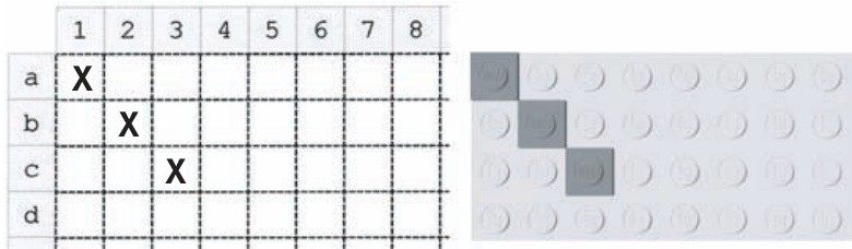
Figure B-3: This side-by-side comparison shows how marks made on the Design Grid translate into the position of real pieces on the actual baseplate.
You may not always need to reference pieces by their exact location, but at other times, you may find this letter and number system very useful.
Design Grid #3
Grid #3 allows you to plan a model as though you are looking at it from the side. A portion of the grid is shown in Figure B-4. You can see that the boxes (also known as cells) on this grid are much shorter. In fact, each box is the height and width of a standard plate as seen from the side. This configuration is referred to as plate view.
Three of these boxes, just as with the real plates, equal one standard brick in height. The page itself is set up just the way you would read a normal book, with the short sides of the page at the top and bottom.
Design Grid #3 – 1:1 Scale [Plate View – Portrait Orientation]
Figure B-4: A portion of Grid #3 shows the layout of the cells.
This is known as portrait perspective (see Figure B-5).
Figure B-5: Here you can see the entire grid as it appears when you print it out on a page.
Design Grid #4
Grid #4 consists of the same sized squares as Grid #3, but the entire page is oriented with the long sides of the page at the top and bottom. This is known as landscape perspective. The image of the grid (shown in Figure B-6) has been reduced in size so that you can see the orientation of the squares as they appear on a full page.
Figure B-6: This grid is useful for planning models that are wider than they are tall.
Using the Grids Effectively
As noted earlier, the grids included with this book fall into two different categories. Grid #1 is useful for creating things like the floor plan for an office building, the shape of an airplane’s wings, or the layout of walls surrounding a castle. Grid #2 is most effective for planning small, studs-out mosaics. The last two allow you to plan the height of a model and include the side view of such things as slopes and plates. You can also use them to plan mosaics or help you design custom-sized arches that you make from inverted slopes. Which grid you use depends on what part of the model you are trying to design. A large model may, in fact, not even fit on a single grid. In that
case, you can either use the grid to work out only a portion of the model, or you can simply tape several sheets together until you have enough room to complete your design.
Same Model, Different Views
You can and should use two, three, or all four of the different grids when designing a model. For example, if you are sitting down to design the train station model from Chapter 3, you might use Grid #1 to plan the layout of the walls, including the ticket counter and the front door. Grid #2 is, of course, most useful for planning mosaics (see more about mosaics in Chapter 8). Grid #3 is handy for just about any model or even just experimenting with combinations of parts. You might then use Grid #4 to sketch the front of the train station indicating where you plan to put the windows and the bench. Like any tool, the Design Grids are intended to make your life easier, so use them as much or as little as you need.
Sketching or Planning
Because the grids are sized to the exact dimensions of LEGO elements, you can use them effectively in two ways. The first method is to simply sketch out your model on the grid, not worrying about which pieces go where. Then, when you have the basic model drawn out, you can find pieces in your collection that match the shape you’ve created on the grid.
The second way is to draw specific pieces onto the cells in order to see how they look. You might do this if you don’t happen to have a specific piece but are planning on buying some. Or, you might use this method to simply try out some different part combinations without having to get out several of your storage boxes.
Colorize Your Ideas
The grids aren’t just effective for planning the positions of pieces. You can also use them to test what certain color combinations might look like. To do this, draw the outlines of the pieces with which you want to experiment. Then color them in using colored pencils, crayons, or fine markers. You can even test the look of color combinations for parts you may not yet own. It’s an easy and inexpensive way to figure out what parts you may need for future projects.
Description and Date for Future Reference
There are also spaces provided at the bottom of each grid to fill in the description of the model and the date the design sketch was made. Figure B-7 shows an example of the kind of note you can make for yourself using this part of each grid.
Figure B-7: Descriptions don’t have to be fancy. Jot down just enough information to remind yourself of the purpose of this particular design.
You may want to keep some of your designs in safe place. That way, as you design future projects, you can look back to see your past efforts—what did and did not work.
Drawing on Grid #1
Remember, Grid #1 presents a view just like you’d see if you were looking down on the map of a town. You see things as though you are floating high above in a hot air balloon. You can’t see the sides of any object from this view, only the tops. For example, if you were to draw the Empire State Building micro model (from Chapter 6) onto a copy of Design Grid #1, you would end up with something like the drawing shown in Figure B-8.
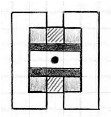
Figure B-8: A microsized Empire State Building as seen from above.
You can use this particular grid in several ways. First, you can use it to determine the various heights of layers within the same model. As you can see in Figure B-8, I’ve used various shading techniques to represent different levels of the building. Areas are shaded light and dark gray, other parts are indicated by diagonal lines, and still other portions have been left blank. Each of these different patterns or shades indicates that the height of the model is different than it is in a differently colored/shaded area. This treatment reminds me to pay attention to the changing geometry as I construct the building, and it is also a way that I can represent three dimensions on a two-dimensional diagram.
You can also use Design Grid #1 to plan the outline of something, like we did with the shuttle wings in Chapter 10, or to see the distances between walls within a building, as with the train station example from Chapter 3, or even the distance between two small buildings.
If you’re going to use it for outlining, then it’s really only necessary to draw a line around the outside of the shape and then use the grid to fill in the needed bricks. Figure B-9 shows part of the shuttle wing that we designed back in Chapter 10.
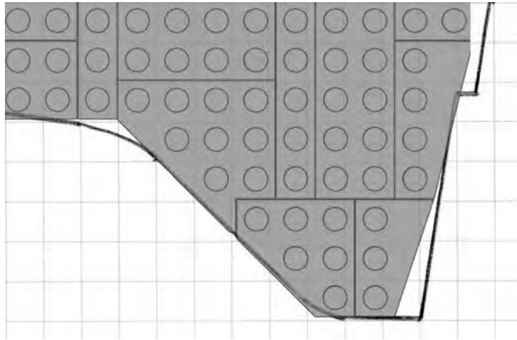
Figure B-9: Using the Design Grids, you can literally piece together a model design by placing real elements on top of your paper sketch.
In the case of buildings, you can use the grids to plan where the walls will be and also how features such as doors and windows will fit in. Figure B-10 shows what a portion of the train station walls from Chapter 3 might look like.
Figure B-10: Make notes to remind yourself of different features or substructures.
Of course another good use for Design Grid #1 is to help plan studs-out mosaics. As I noted in Chapter 8, the studs-out style isn’t as subtle as the studs-up variety, but such mosaics can still be fun to plan and build. See Figure B-11 for a simple example.
Figure B-11: Simple characters and themes are good subjects for studs-out mosaics.
Drawing on Grid #2
One way of using Grid #2 effectively is to find an image you want to turn into a mosaic. Print out a copy of the grid and a copy of the image on a separate piece of paper. If possible, resize the image to approximately inches square and center it in the middle of the page. Then, when you set the grid sheet on top of the printout of the image, the two sheets will be aligned. This will, more or less, cause the image to fall within the length and width of the grid itself. To plan your mosaic, simply trace whatever parts of the image you want to reproduce in bricks. In Figure B-12, you can see that I’m beginning to sketch out a simple example.
Figure B-12: If possible, try to use lightweight paper when printing out Grid #2. This will allow your image to show through from below.
NOTE Refer to Chapter 8 for even more information on using Grid #2.
Drawing on Grid #3
Design Grid #3 represents an entirely different view than you saw on Grids #1 and #2. In this case, you perform the model planning as though you are looking at the bricks and plates from the side. If you were to simply draw a single plate, it would look like Figure B-13.
Figure B-13: As simple as it gets. This illustration shows you what a plate should look like.
A standard brick would then look like Figure B-14.
Figure B-14: Three plates stacked together always equal the height of a standard brick.
As you can see, each time you want to draw the equivalent of a full-height brick, you simply draw a line around three of the cells. You draw longer bricks, such as a bricks, by extending the top and bottom lines until you have captured the length you need. Figure B-15 shows what a arch brick would look like when drawn on this grid. You don’t need to limit yourself to just standard bricks and plates; you can draw other pieces just as easily.
Figure B-15: Parts with complex shapes, such as the arch shown here, can also be easily drawn on the Design Grids.
You can also indicate slopes on this grid by drawing diagonal lines along with lines for the bottom and side of the element (see Figure B-16).
Figure B-16: Follow the geometry of a real element, and your drawings will always be accurate.
For example, in Figure B-16 you can see a 45-degree slope and a 33-degree slope. Notice that the diagonal lines cut across the lines of the grid itself, but that’s to be expected. If you are ever confused about which lines to connect to make the sloped side of the piece, just grab an actual slope from your collection and study where the slanted edge meets the rest of the brick. Don’t forget to leave a flat line at the top to represent where the stud is located.
Drawing on Grid #4
Once you understand how to use Grid #3, you know how to use Grid #4. The only real difference between the two grids is the way the pages are oriented. As noted earlier, Grid #3 is used in portrait perspective, whereas Grid #4 is in the landscape perspective. You’ll find Grid #3 useful when your model is taller than it is wide. Obviously the opposite is true for Grid #4.
Figure B-17 shows an example of testing a particular combination of parts—to view their final shape—without ever taking a piece out of storage. As you can see, the drawing isn’t perfect, but it can help you make some key construction decisions.
Figure B-17: Inverted slopes are just as easy to draw as their standard counterparts. Here I’ve sketched out a substitute arch, not unlike the example you saw back in Chapter 3 (Figure 3-25).
Review: From Grids to Bricks
You will always need to tweak your model as you translate it from a sketch into real bricks, but by doing so, you should end up with a stronger design. The drawings you create on the grids should only provide you with a guide; you don’t have to follow them brick for brick. The best thing to do is to create your design sketch and then simply start building the real thing. As you work, you can step back, examine the actual assembly, and see which bricks or plates you want to change. The result, whether a small group of pieces or a complete mosaic portrait, will be a work of art that you can call your own.
theLEGO NEIGHBORHOODbOOK BUILD YOUR OWN CITY! BRIAN LYLES AND JASON LYLES
theLEGO 2 NEIGHBORHOODbOOK BUILDYOUR OWN CITY!BRIAN LYLES AND JASON LYLES
Introduction

In our first book,TheLEGONeighborhoodBook,we had a great time teaching you techniques for making your own buildings and giving you ideas and inspiration
This timearound,we’dlike to give you a tour of some new neighborhoods and show how they connect to make a bigger city.Along the way,we’ll lookat new
techniques,find some cool things to build, check out architectural styles in the cityandexplore waystobring your own city to life.
We can’t wait to show you what we’ve created-but before we get started,here’s a quickoverviewof the Café Corner Standard for modular buildings.
Thebuildingsconnect toformablockorrow ofbuildings.
Base Size
All modular building sets to date use a -stud base,composed of either a single plateortwo plates. So,to adhere to the standard,you need to build in 16-stud-wide increments too: and so forth.You can,of course, create larger buildings by combining baseplates.
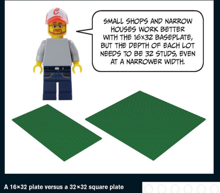
Connecting the Buildings
Buildings are connected to one another at the base via LEGO Technic pins. You’ll use four Technic bricks (part #3700) and two Technic pins (part #2780) for each connection.
Of course,you must space these Technic bricks consistently to match other buildings.
For a corner building,the placement of the Technic bricks remains the same: the 9-stud, 10-stud, 9-stud pattern shown at right.
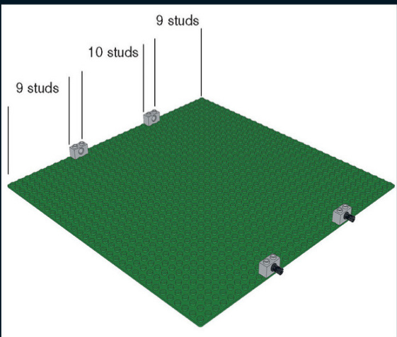
Even though you don’t have a building yet, you’ll want to place these Technic parts first for planning purposes. Technic pins hold your town together. They also allow you to build houses separately and connect them when you’re finished. Corner buildings maintain the same connections at the same spacing, just on a different side of the plate.
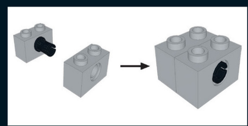
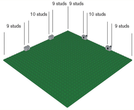
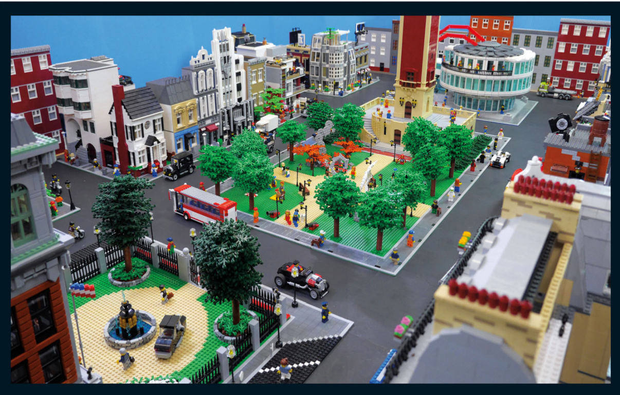
A Residential Neighborhood
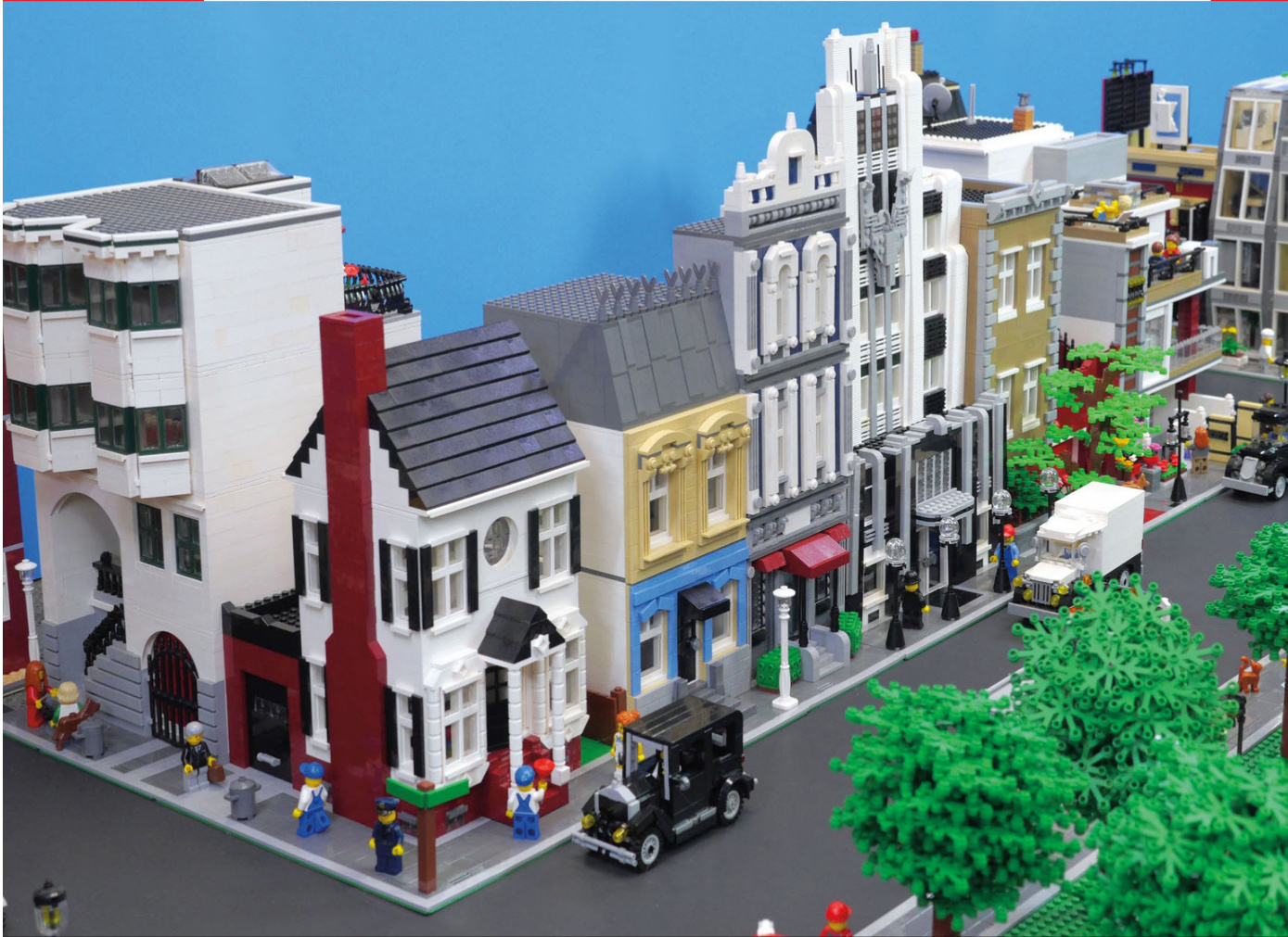
American Colonial
The American colonial style is a common sight in older cities along the East Coast. Older houses like this one don’t have fancy curves.Because this house is placed on the corner, the facade and the dramatic chimney are visible to passersby.The old carriage house has been convertedto a garage.
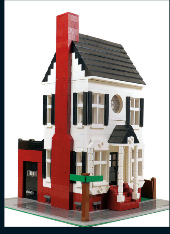
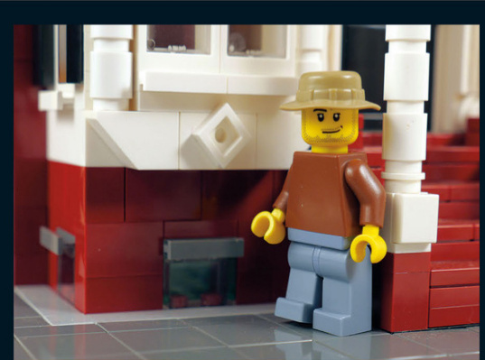
This old house was built on the outskirts of the city during the late 19th century. These small windows at street level allow natural light to pour into the basement - an important consideration in the age before electricity.
This round window was achieved with opposing arch pieces. The bottom arch isn’t secured, but it stays in place.
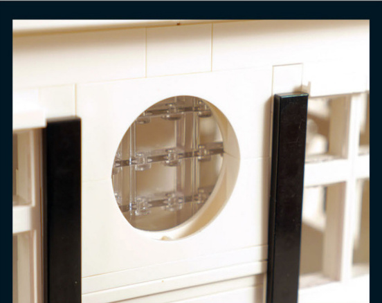
A fancy trim adorns the front windows.The round columns on the front porch help frame the stairs and hold up the gable.There are hundreds of ways to add ornate trim to make the style your own.
There is a chimney on the side of the house.If you look closely at the eaves,you’ll see where the roof separates from the second floor. The chimney is designed to segment and come off with the roof. This design makes the building easier to assemble and disassemble.
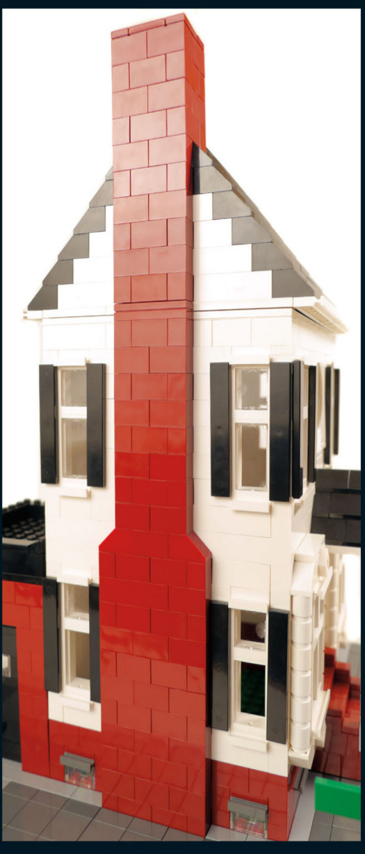
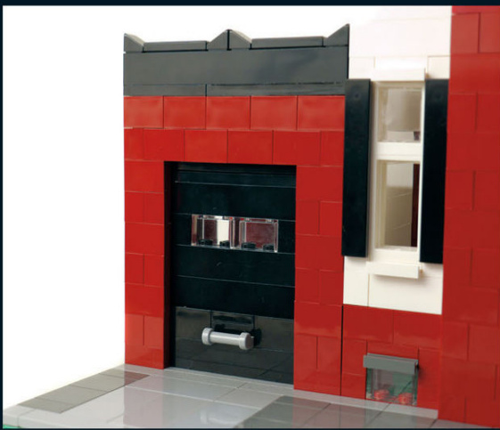
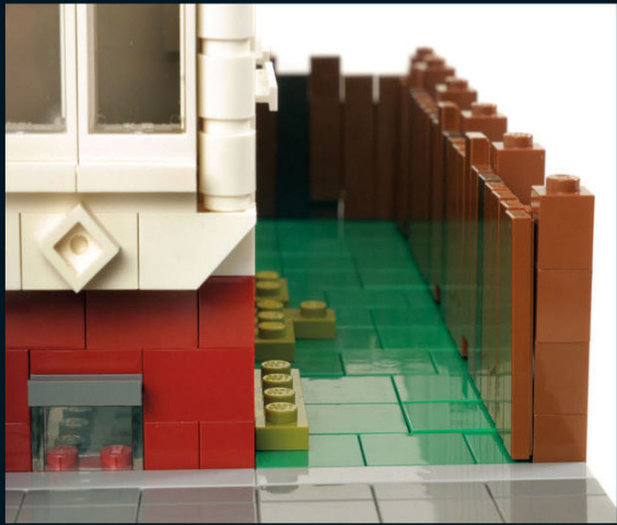
The garage outback served as a carriage house when the main house was originaly built.When designing garages,you can experiment with different doors that roll up,swing out, or open inward.Or you could make a door that has more detail but doesn’t open.
This house hasa sideyardand a backyard that are surrounded byafence.Not allthebuildings on a street have to connect to another wall.Alleys,yards,and parking lots cankeep things interesting.
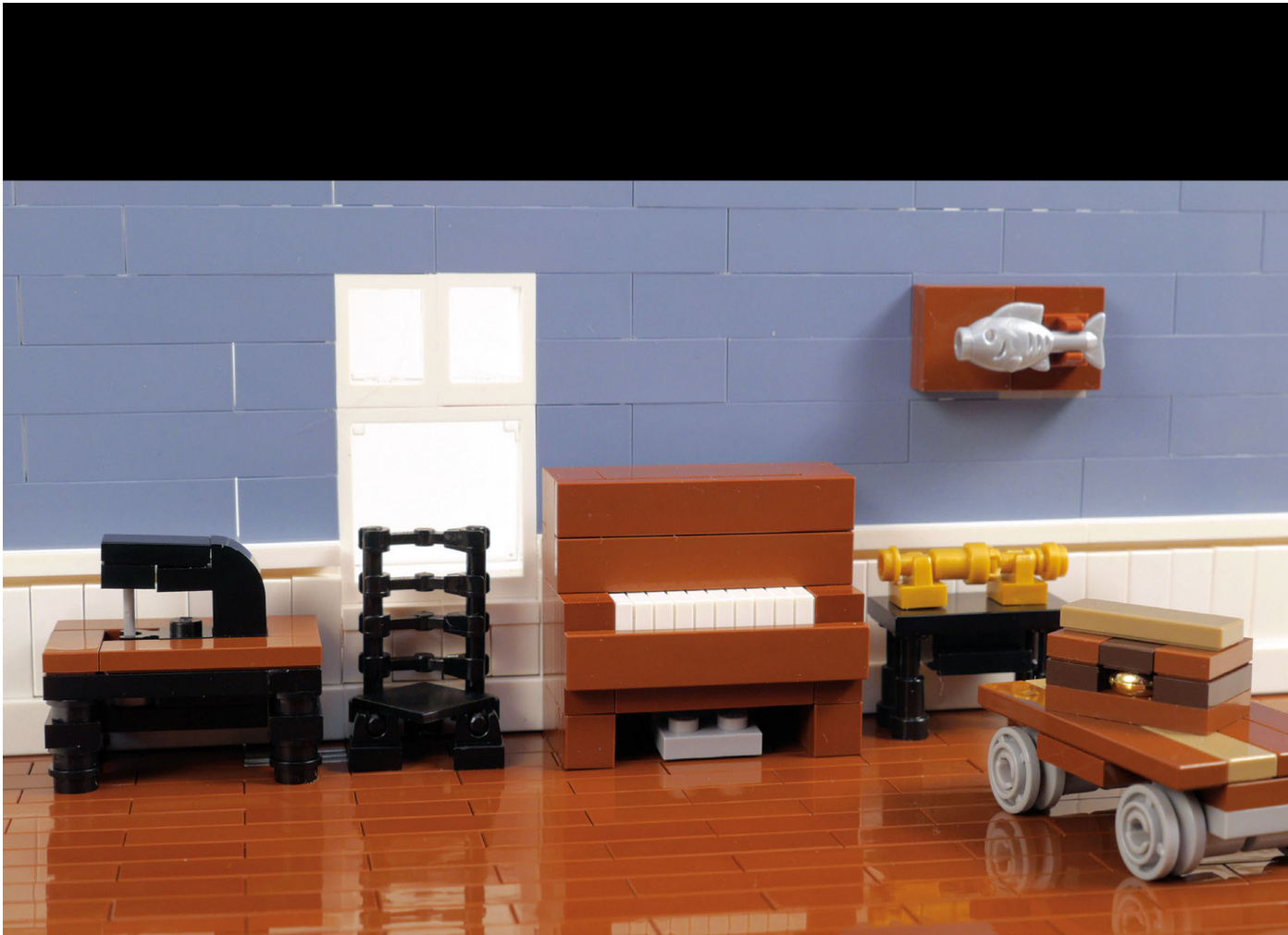
Colonial Interior
Adding details inside your houses can increase the “wow”factor of your city. You might decorate the house to reflect the inhabitants’interests or a certain time period. In this build,you can see some nice antiques and details that look at home in this old house,like the sewing machine table,the piano,and the wainscoting on the wall.
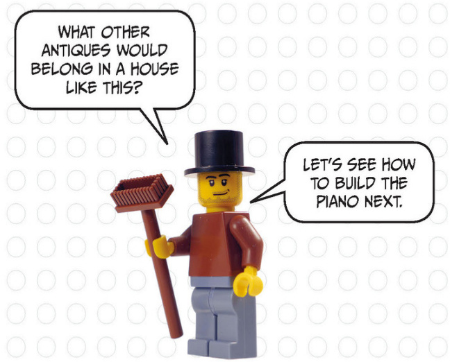
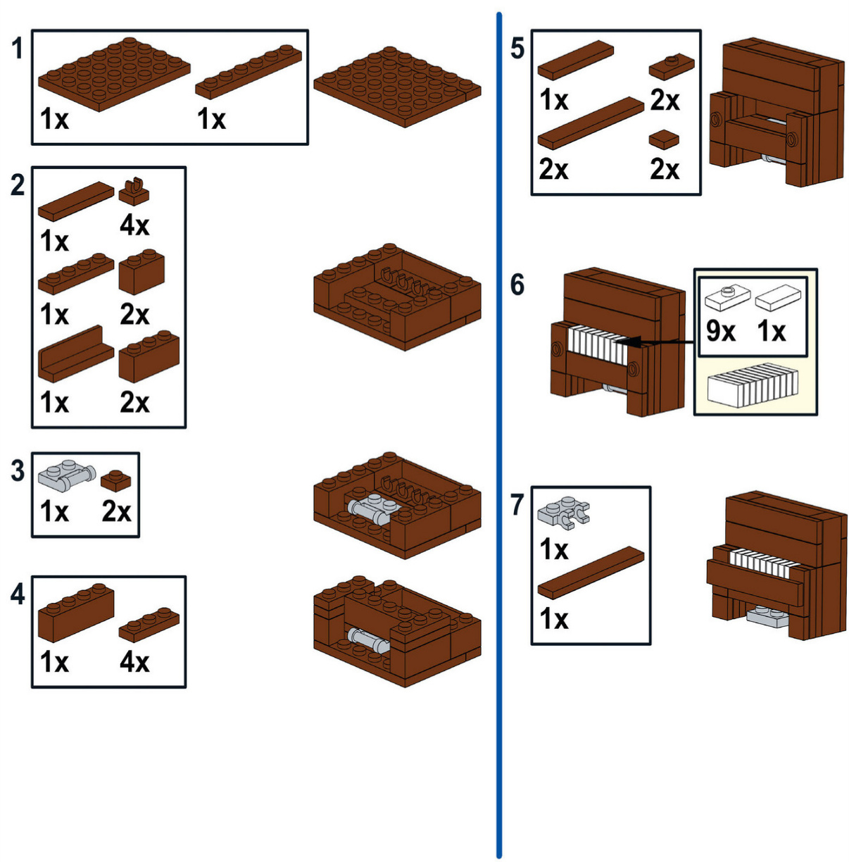

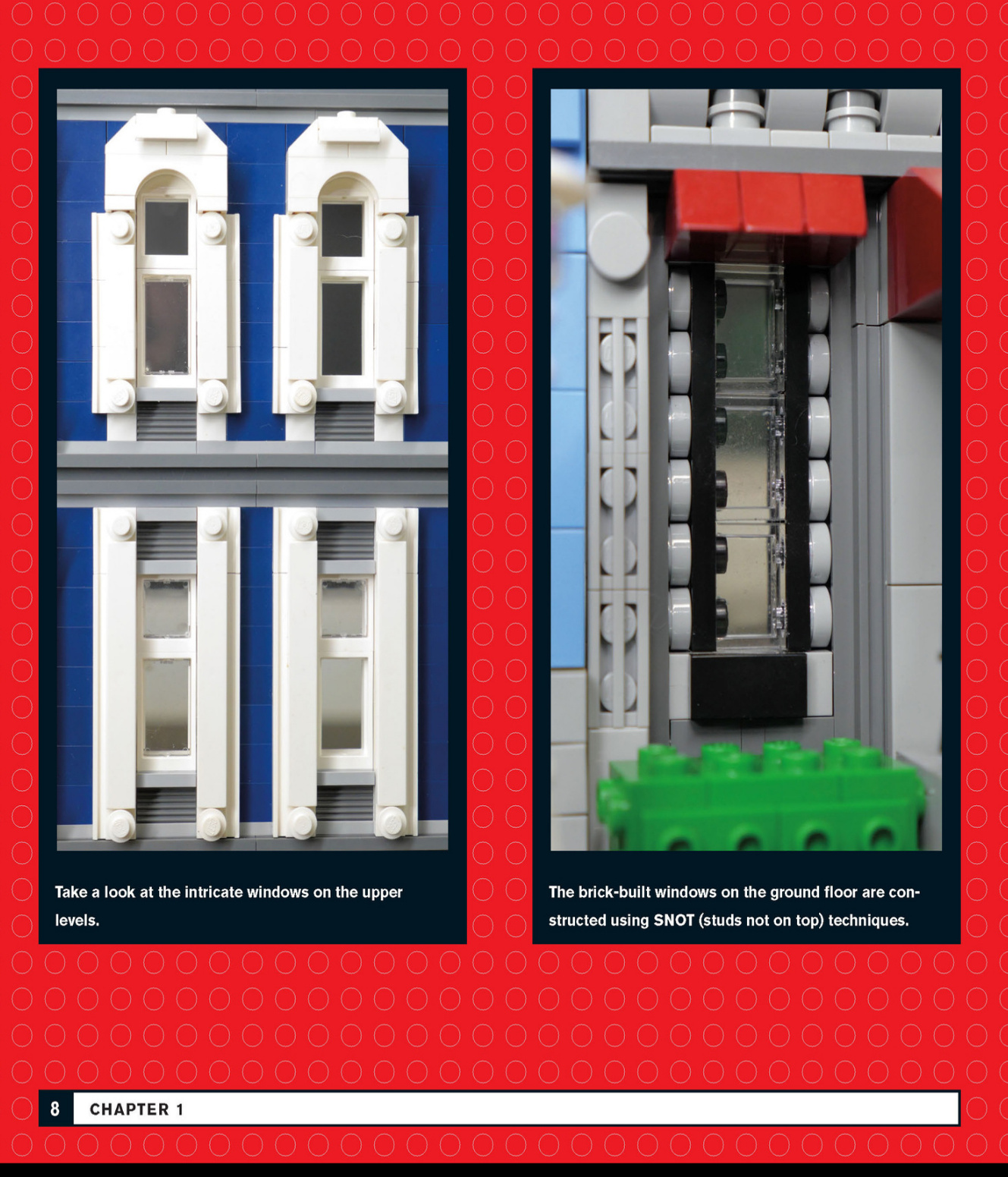
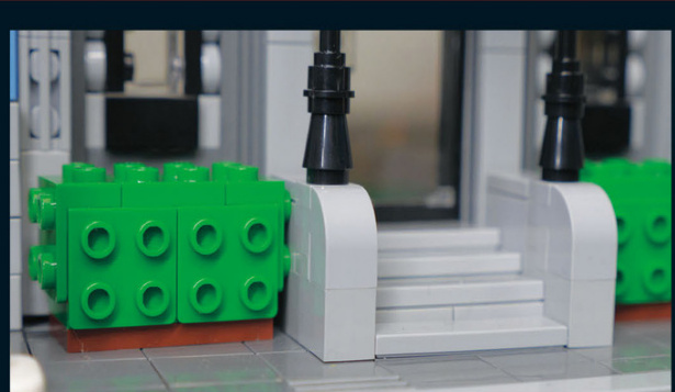
A small set of stairs leads to the first floor of this hotel. Trimmed bushes add a pop of color on each side.
This roofline has a certain elegance that is often found in older European architecture.
The entrance to the hotel has a red awning that matches the window awnings.
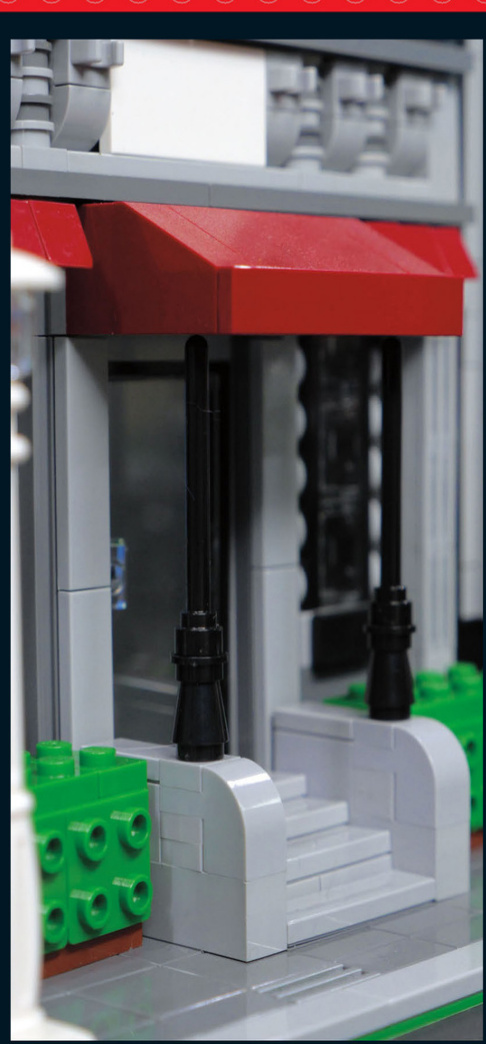
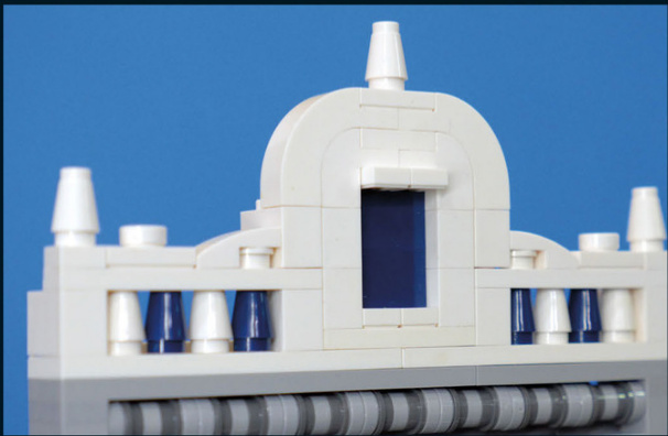
Art Deco Apartment Building
The third building on our tour is an apartment building with flowing lines and lavish ornamentation that make it undeniably art deco in its architectural style.
Art deco is a style particularly suited to being built with LEGO.There are a lot of clean lines,interesting colors,and relatively simple designs.
The vertical lines on the front of this building give it a taller appearance.The light grey represents metal ornamentation on the facade.This apartment building has four lampposts in front to help light not only the sidewalk but thefacadeas well.
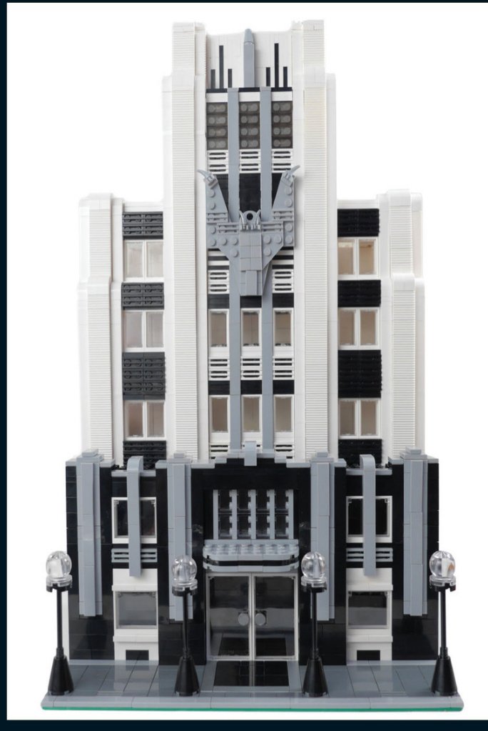
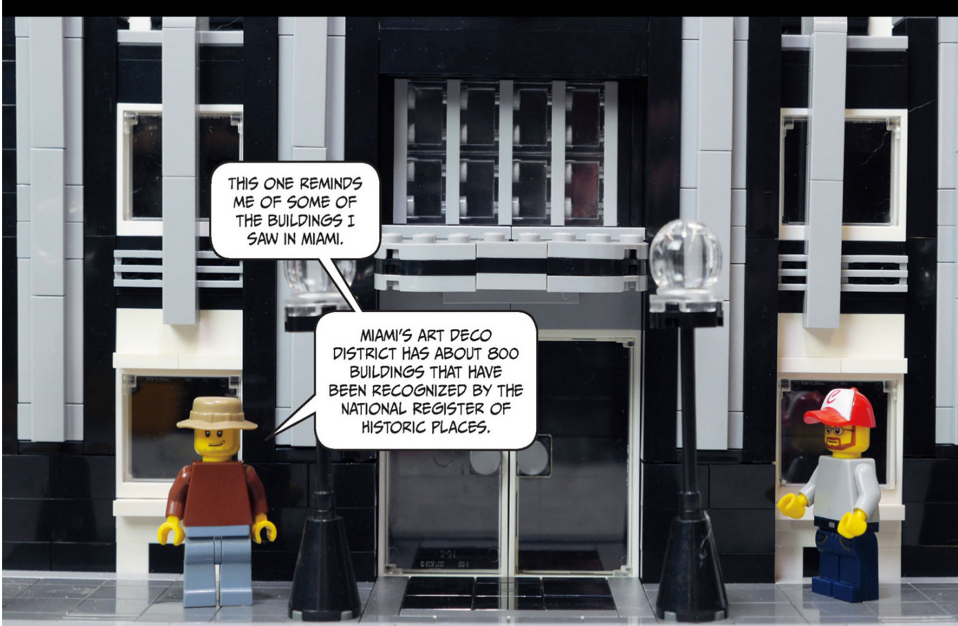
Check out the interesting features on the facade.The curved awning over the door and the decorated windows on each side help to create a grand entrance.
The trim on thelower section of the building is made of metal and has a stepped design, directing the viewer’s eye upward to the rest of the building.

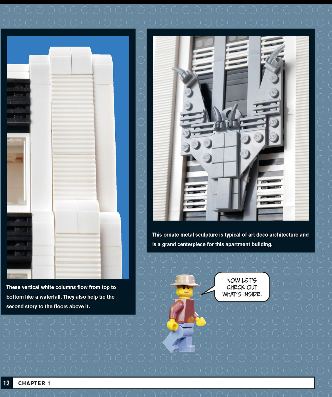
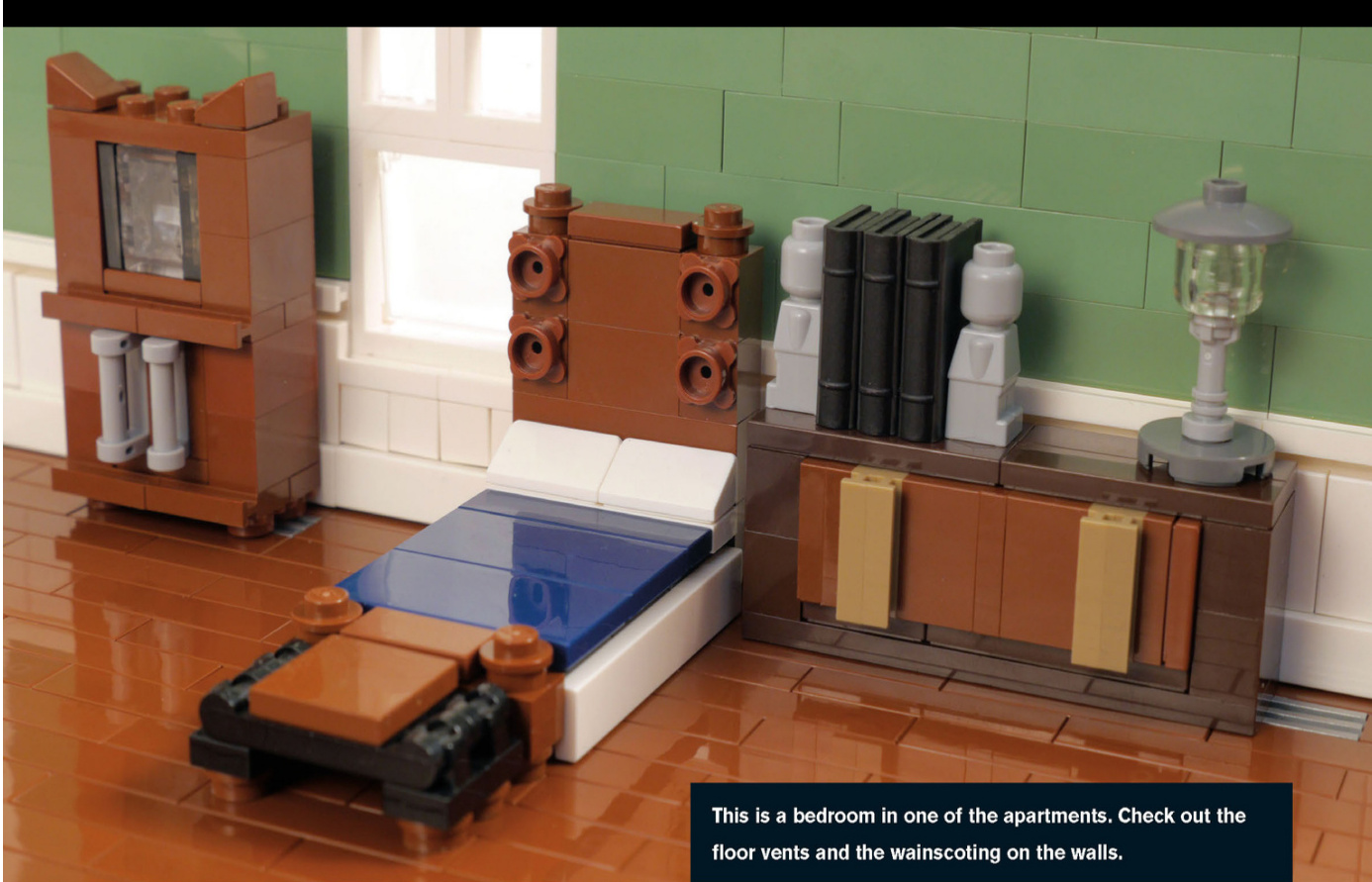
Art Deco Interior
The display cabinet, wooden bed with a skirt, and cabinet shown in this bedroom are all interesting bits of furniture and feature SNOT techniques.
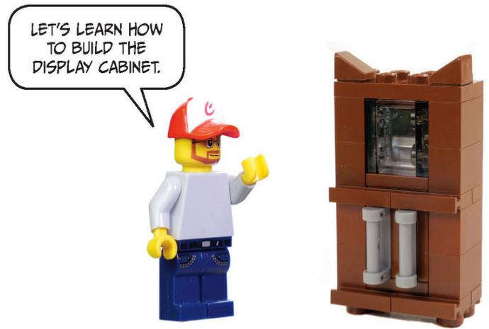
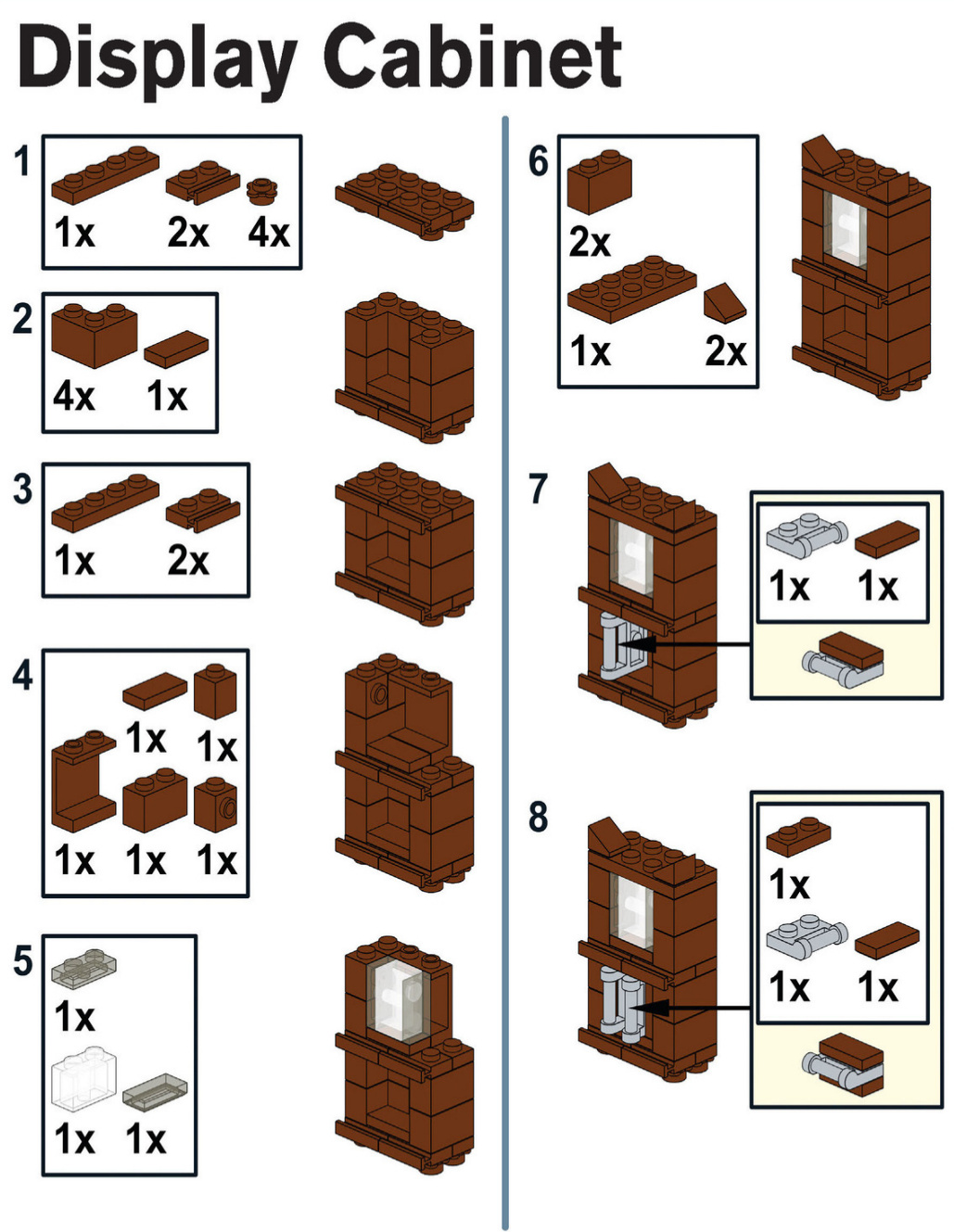
Italianate Row House
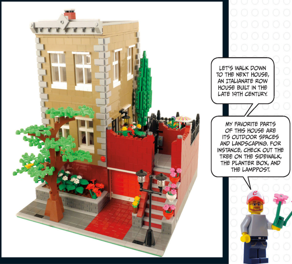
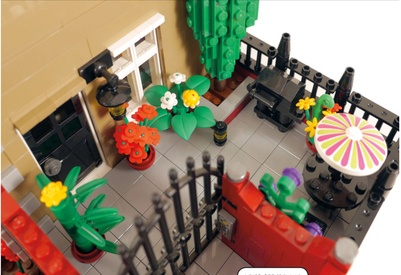
ThispatiowasfeaturedinBetterBricksand Gardens a few months back.The construction of the bush relies on SNOT techniques to attain the shape of a tall manicured bush.
LET’SSEE HOWTOCONSTRUCT THEGRILL.
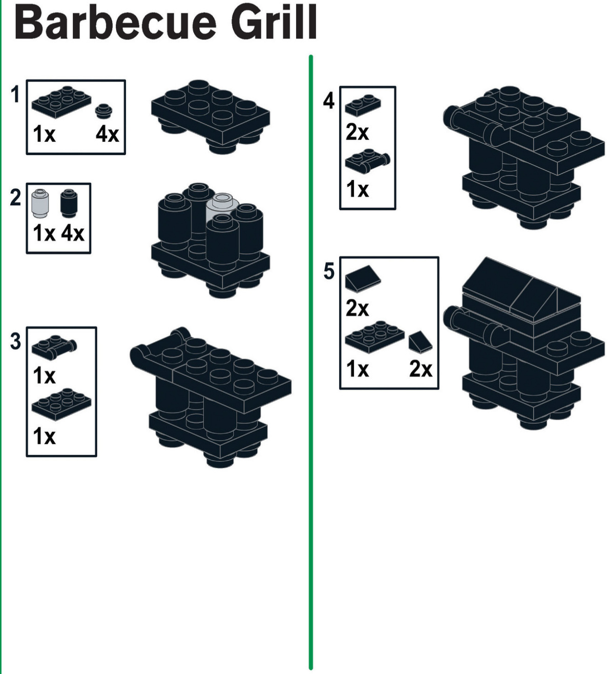
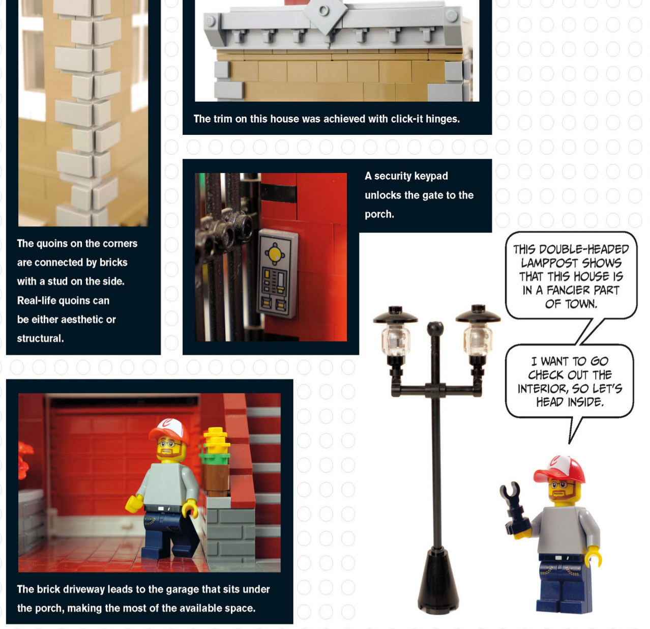
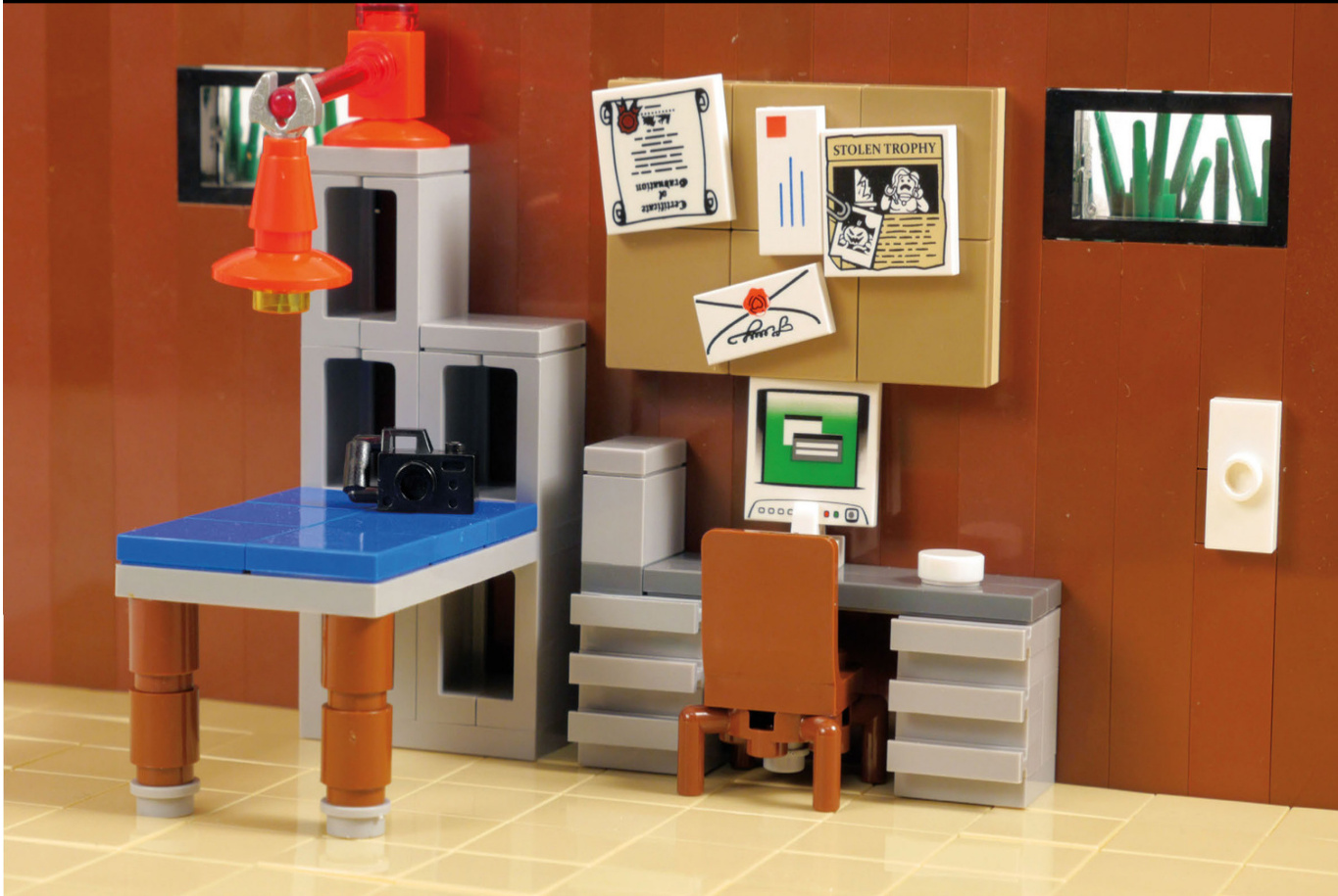
Modern House
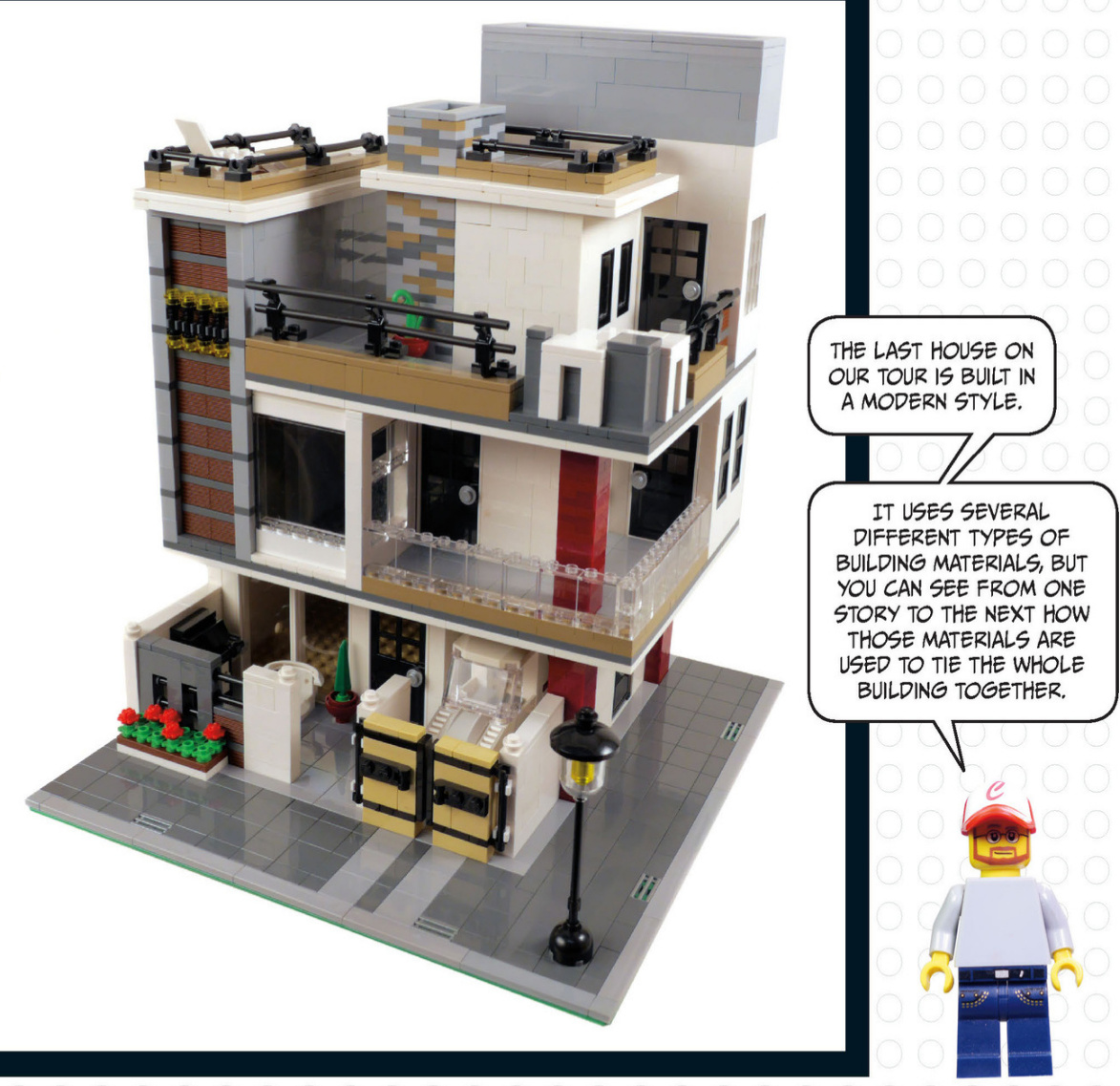
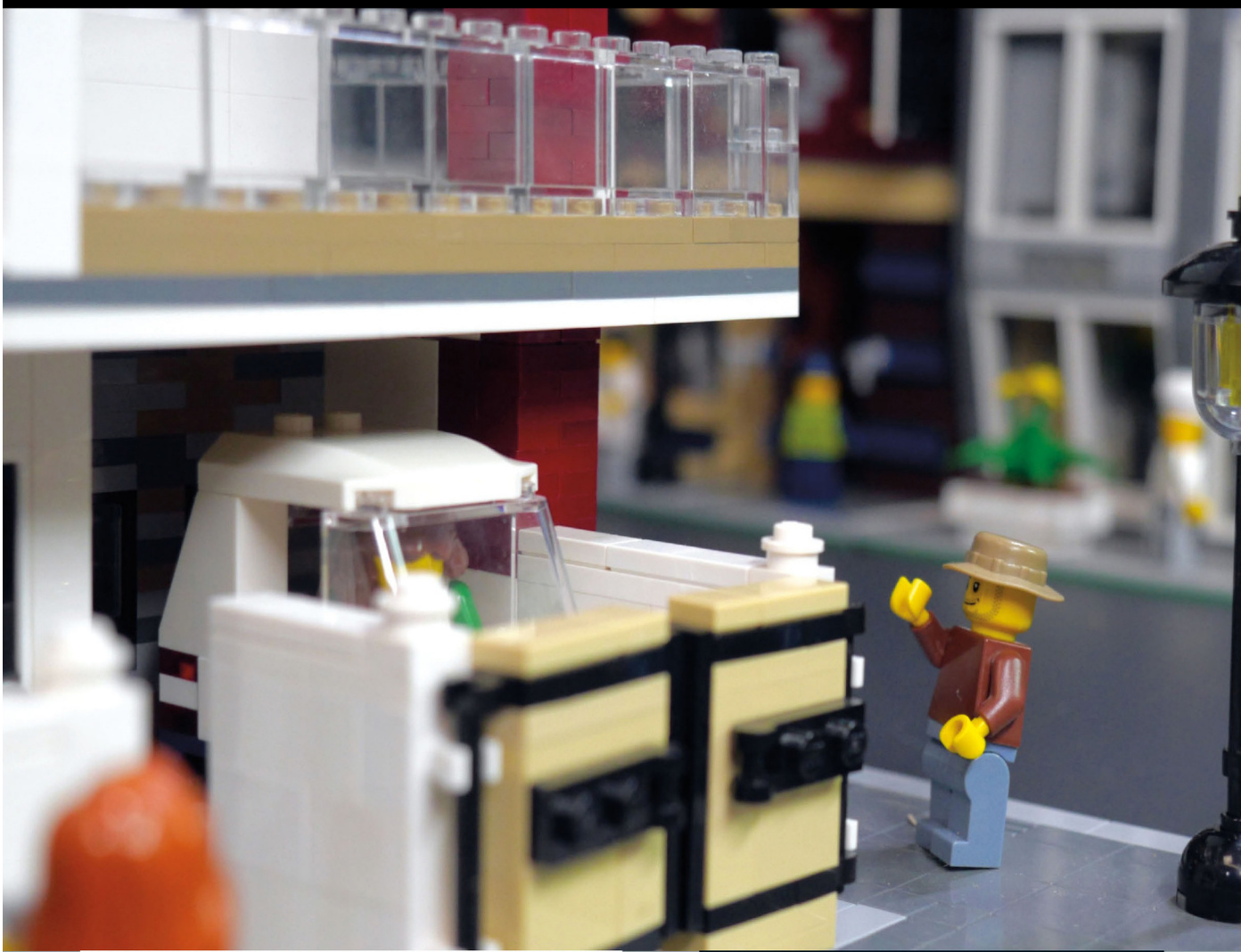
Note the use of cantilevers in this building. We recently took a tour of Frank Lloyd Wright’s Fallingwater,and he made heavyuse of cantilevers in that house.A cantileveris a portion of a bridge or building that extends away from the main structure but is fixedonly on one end or in the middle.Think of a bridge with a single supporting column in the middle. The roadway on either side of the supporting column balances theload.
Modernarchitectureoftenfeaturesstraightlines, andonthishouse,thelinesarebothhorizontaland vertical, startingdownhereinthecarport.
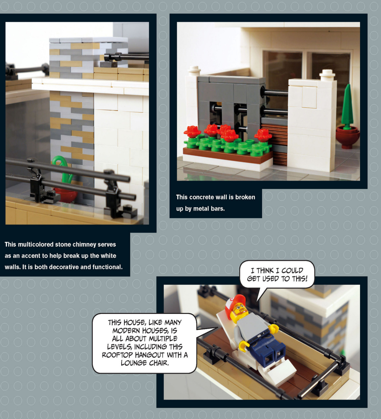
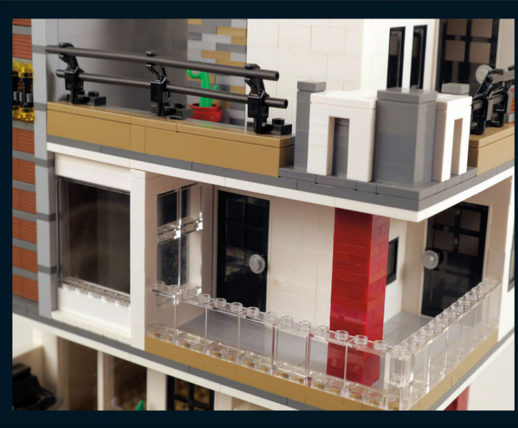
This house has severallevels and features exterior walkways to help connect different parts of the house. The red brick columns help hold up thosewalkways but also stand out as accents because of the stark contrast ofcolor.The red brick columns start on thefirstfloor andcontinue onto the second floor, helping to tie the first floor to the second floor visually.
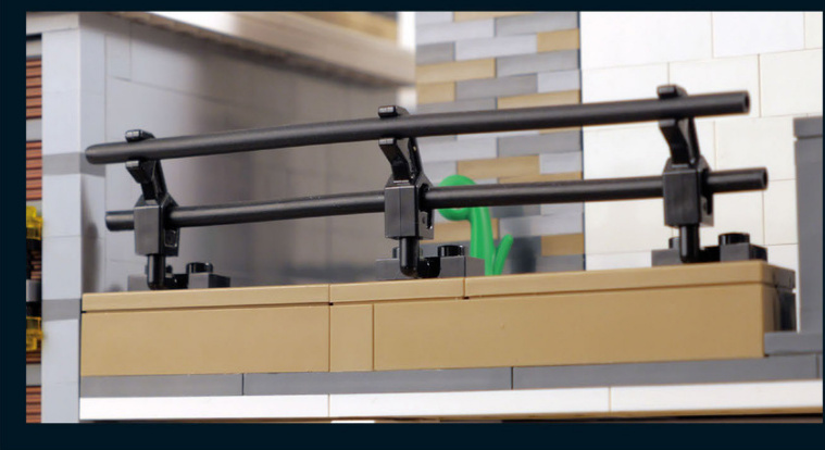
This metal railing on the upper floor provides an almost commercial or industrial look to the house.You can also see black metal railings on the first floor and onportions of the roof.Therepeated use of this material helps create a visual connection from thefirstfloor to the thirdfloor and the roof.
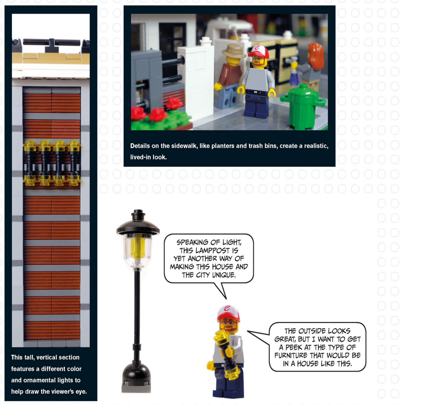
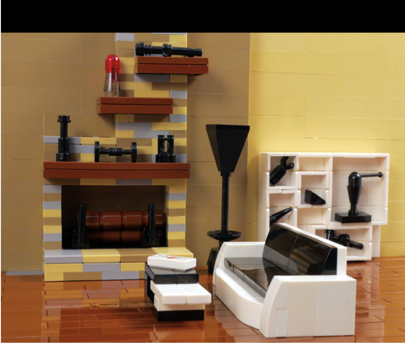
ModernInterior
The modern house’s interior features two different colors on the walls.They’re both neutral colors,which is typical of modern interiors, and there’s a clean split that helps define where one room ends and another begins.
The floating shelves on the fireplace and the open display shelves showcase decorative objects that are all about completing a look.The sofa,lamp,and coffee table all have a similar streamlinedlook andcolor scheme.The coffee table has differentlevels and colors, just like the house.
Let’s see how to build this sleek couch.
Modern Couch
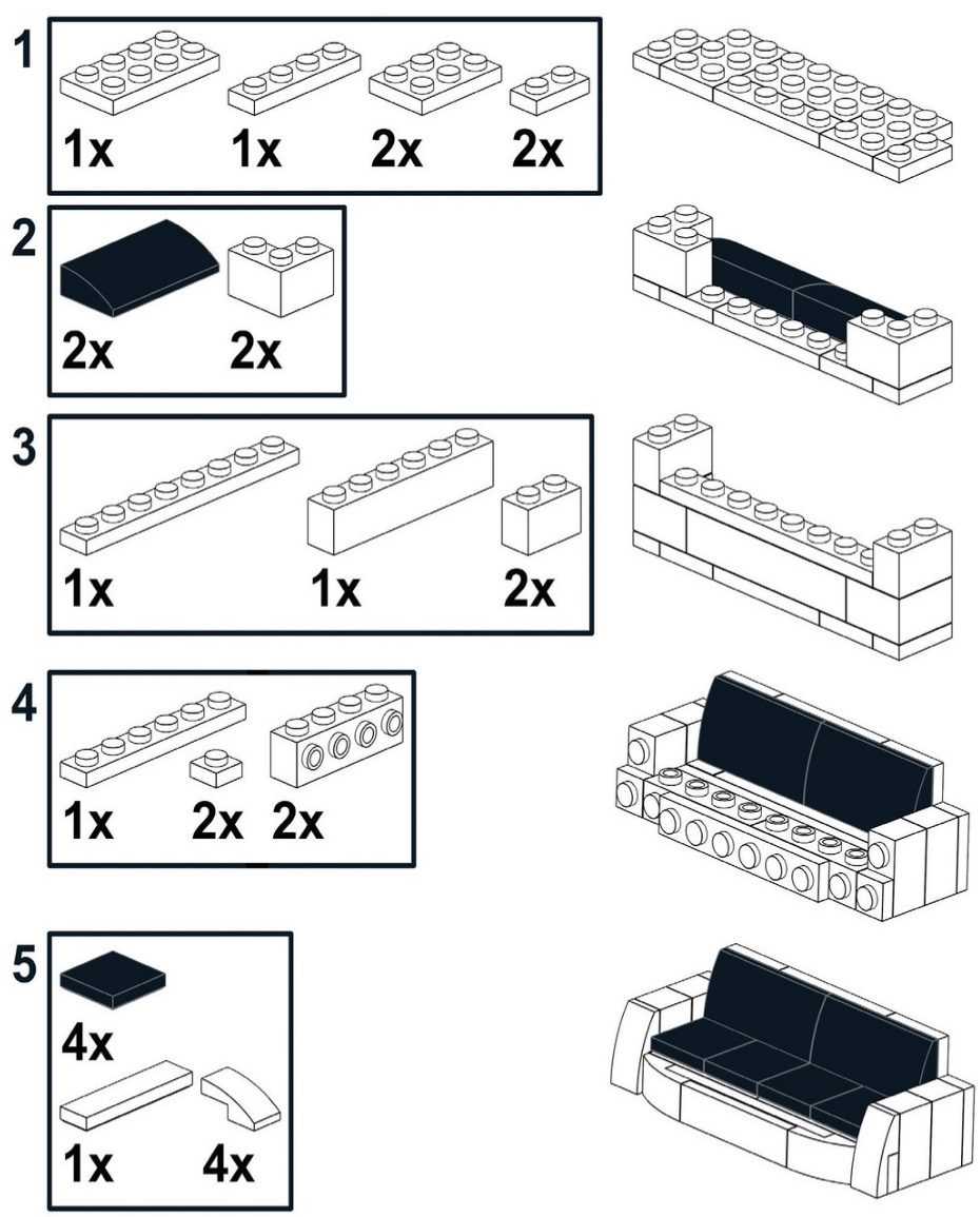
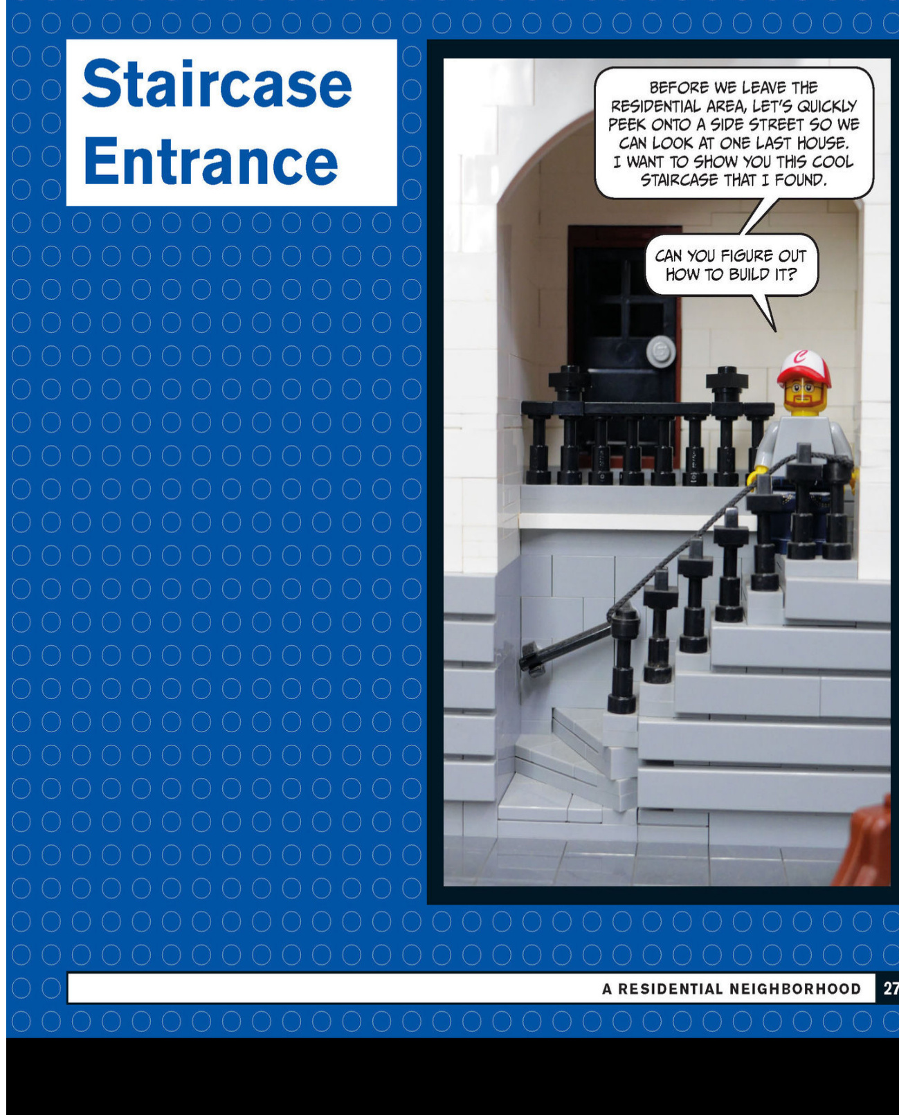
A Commercial Neighborhood
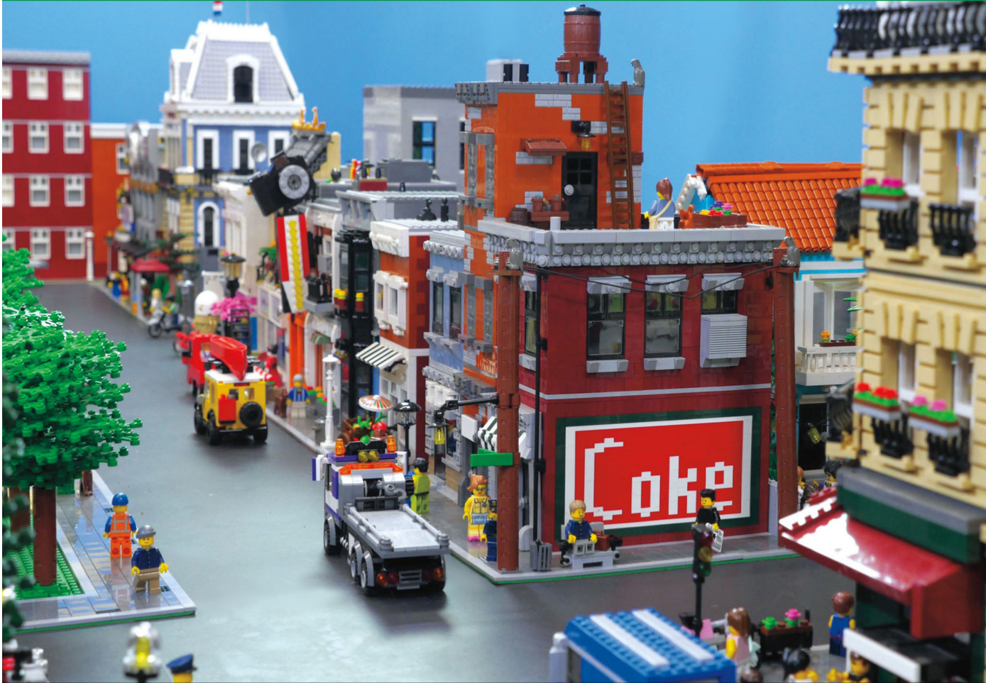
Corner Store
The first two buildings that make up our commercial neighborhood occupy the same baseplate and are located on the corner of the block.The corner store has an apartment on the second floor, and the narrow building next door could be used as apartments or offices.
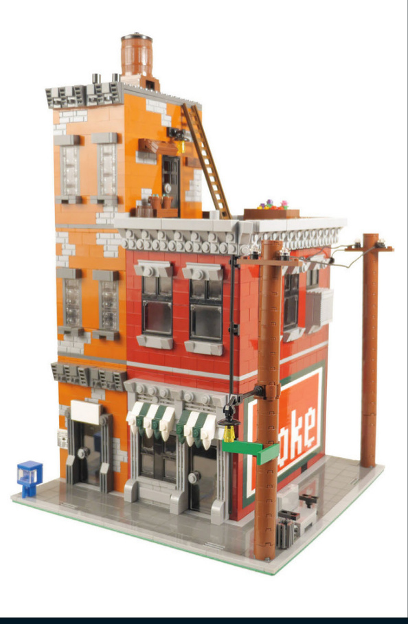
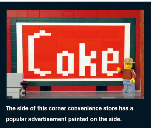
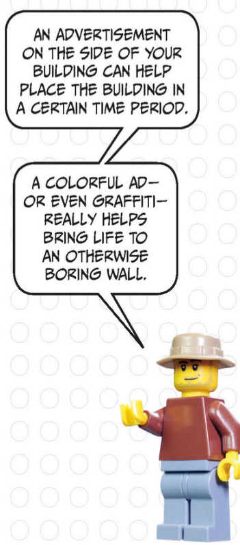
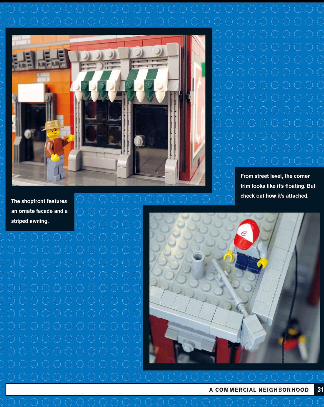
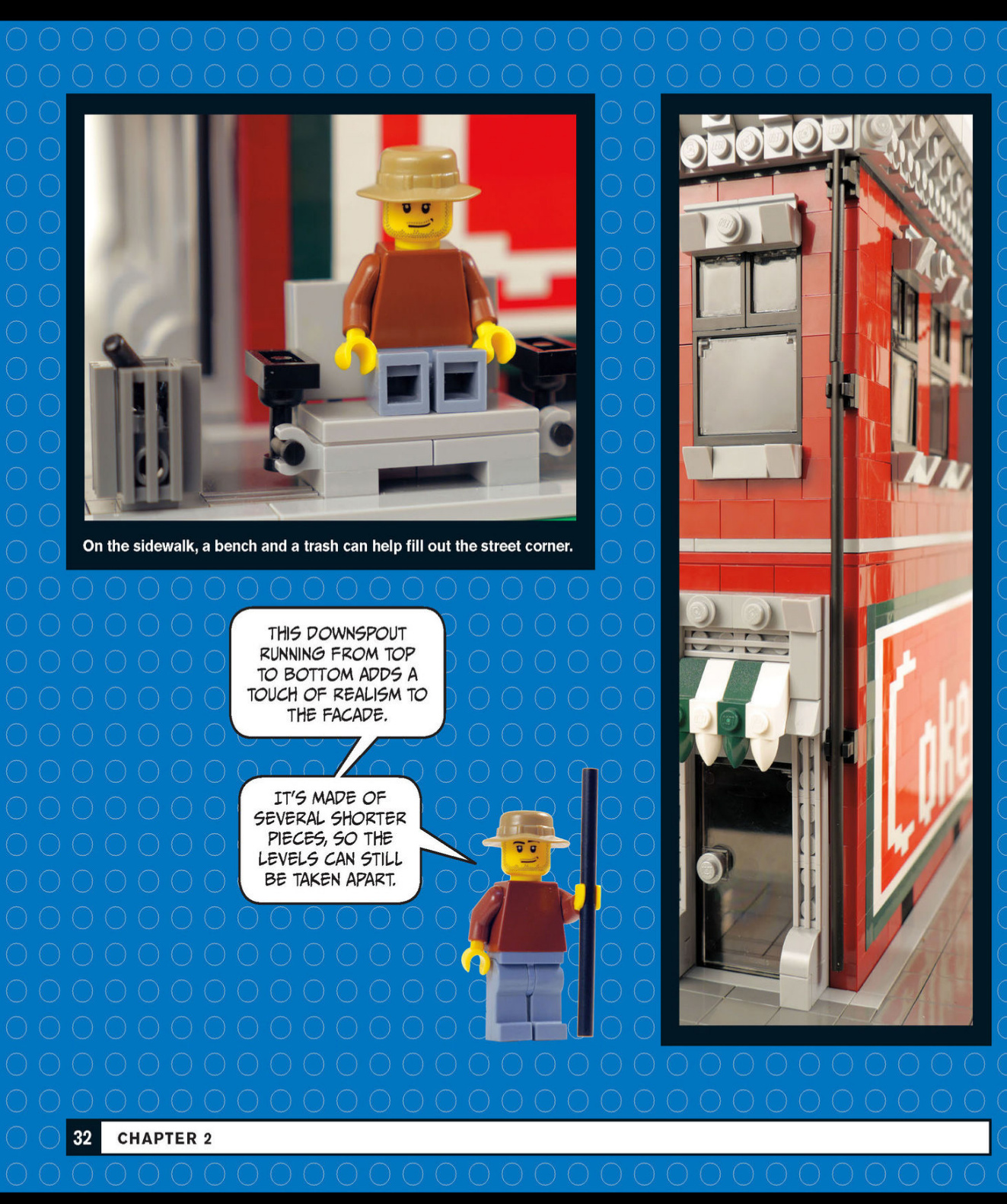
You can have electric poles running along your sidewalks - and don’t forget the lights and street signs that are often attached to the poles.
An AC unit is an often - overlooked detail that can be found in many windows across the city. Consider the time period of your city to help determine what would be appropriate. These power lines feature glass insulators as a nice detail. AC units add realism to any building.
This utility pole includes a streetlight and signs.

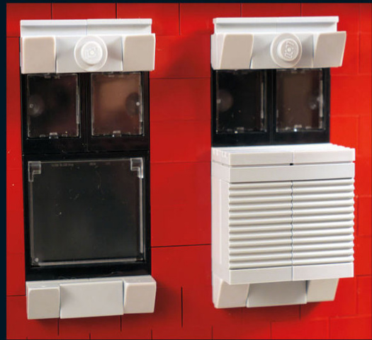
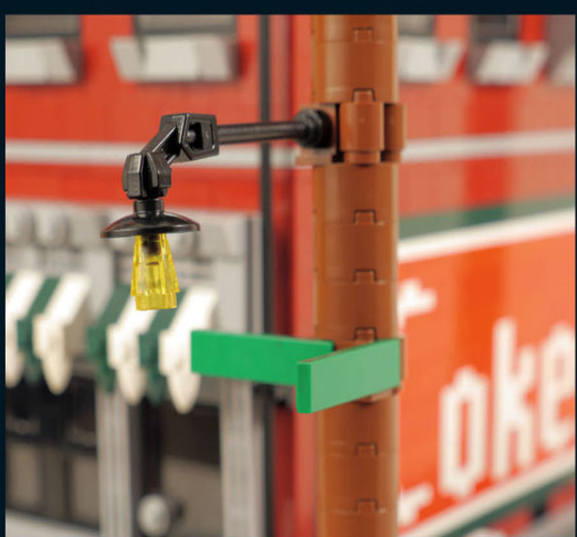

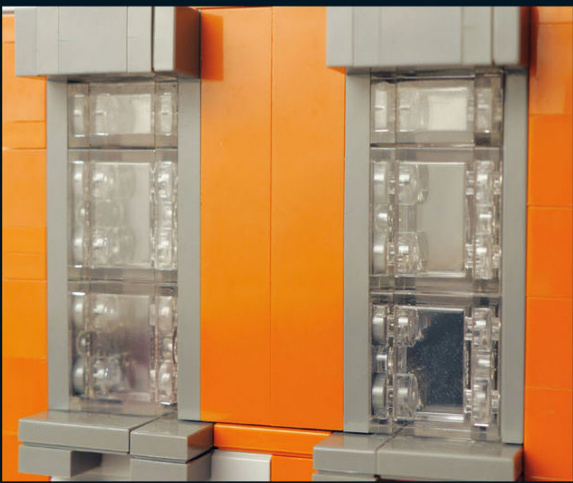
This rooftop garden adds flair andpersonality to the building.It brightens up the roof and provides a muchneeded“yard”for city dwellers.
Sometimes you might be missing a prebuilt window in the color you want, which forces you to get creative. Take a closer look at these windows made out of clear bricks.The windows are built almostentirely sideways.
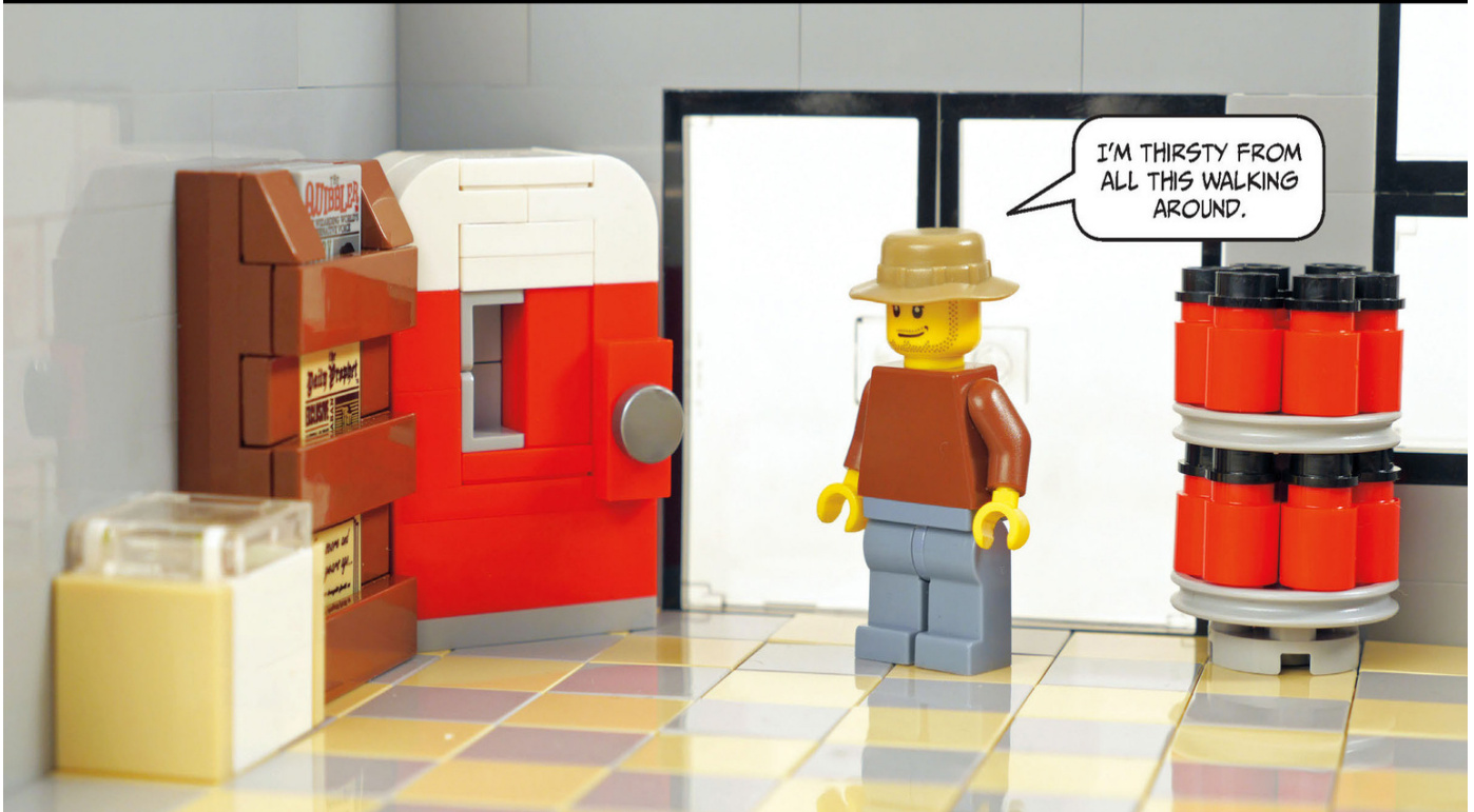
Corner Store Interior
This store has a soda machine, a newspaper rack, an ice - cream chest, and a turnstile display holding motor oil. The vintage soda machine will look great if the setting of your town is the ’30s or ’40s. Let’s see how to build it.
A newspaper rack is a great way to display your decorated tiles.
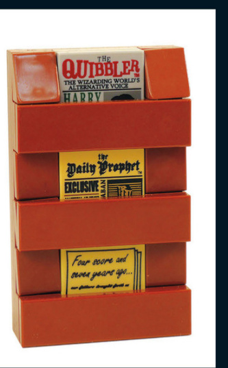
Soda Machine
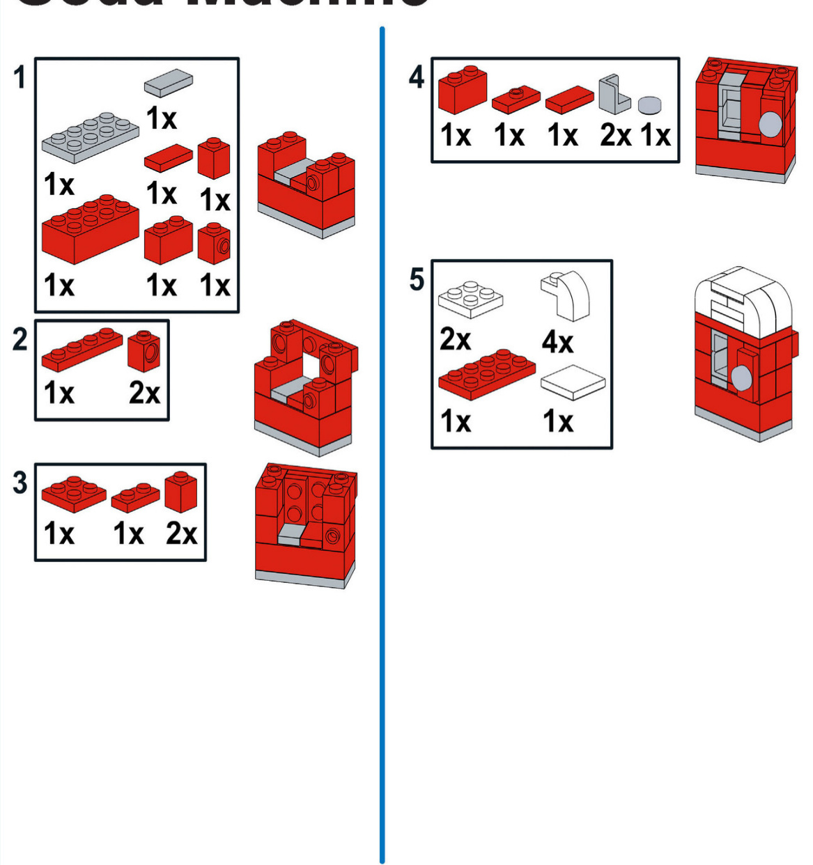
Small Shops with Alley
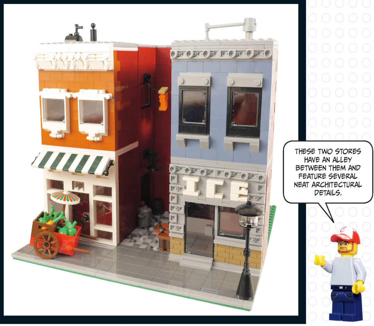
This ice sign features another way of creating letters. The backward plates around the sign create the look of a carved stone trim. This vegetable cart can be rolled back home at the end of the day.
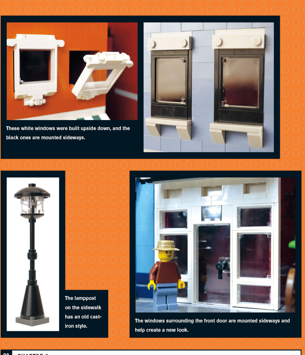
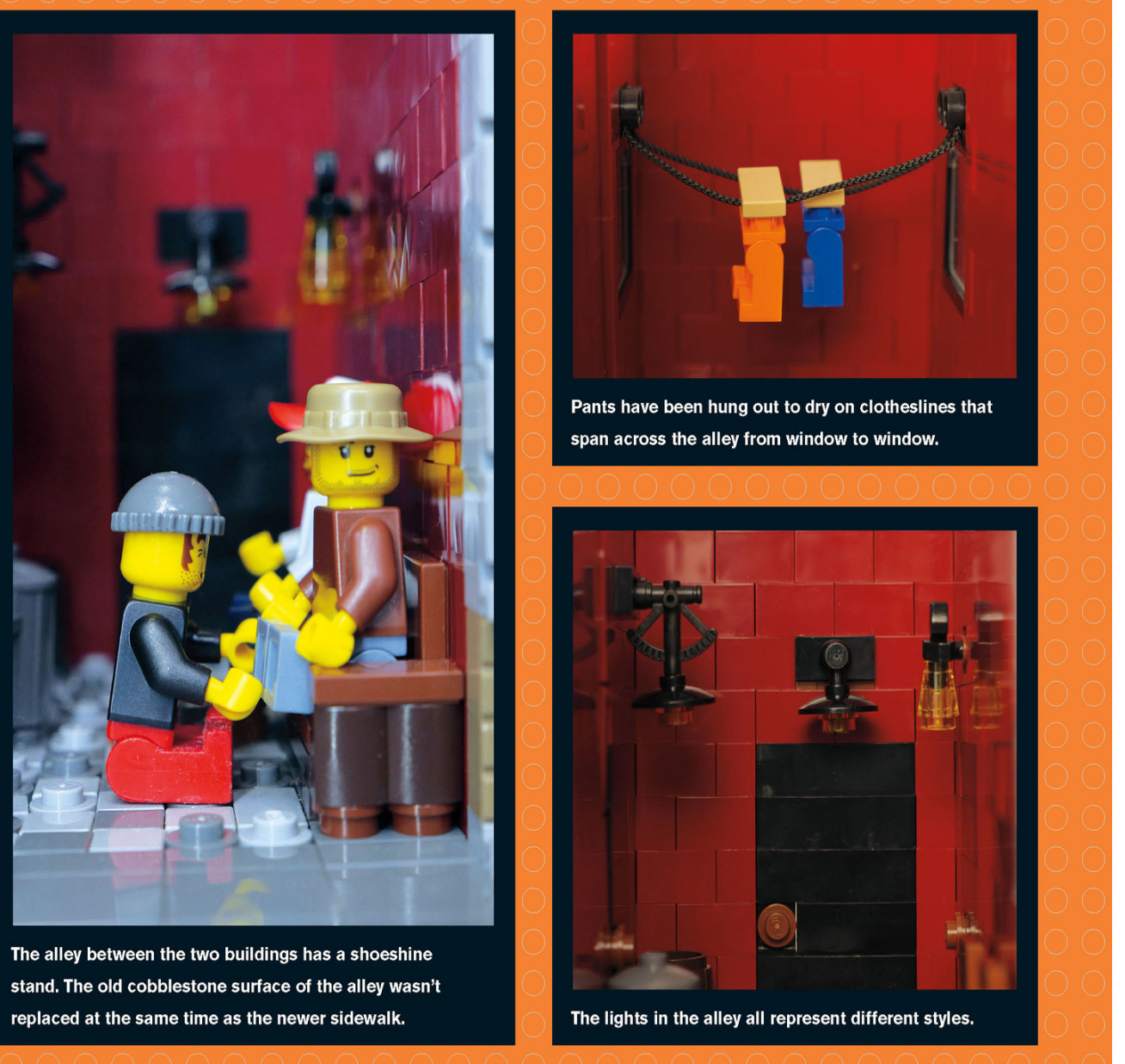
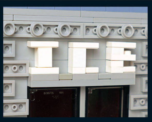
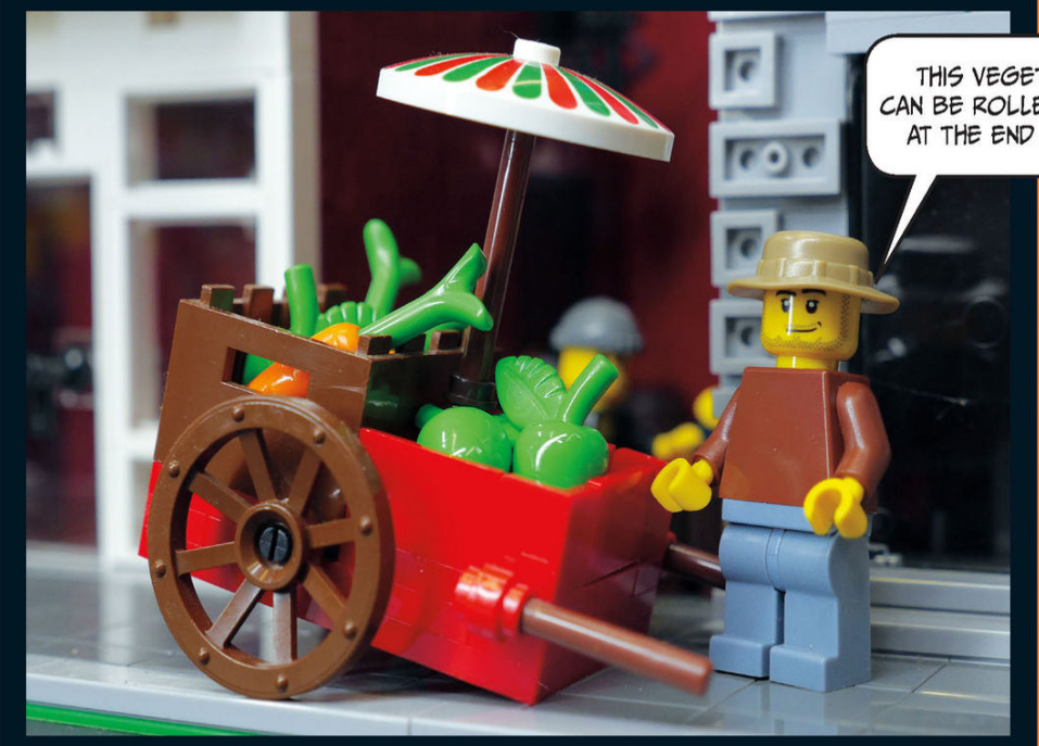
Shop Interiors
Check out the furnishings inside these shops!
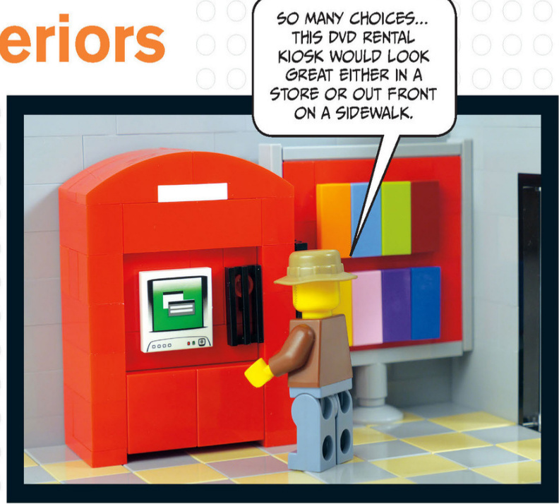
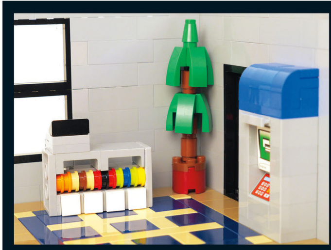
Adecorativeplant,anATM,anda checkoutcounter,completewitha candydisplay,roundouttheinterior
DVD Rental Kiosk and Sign
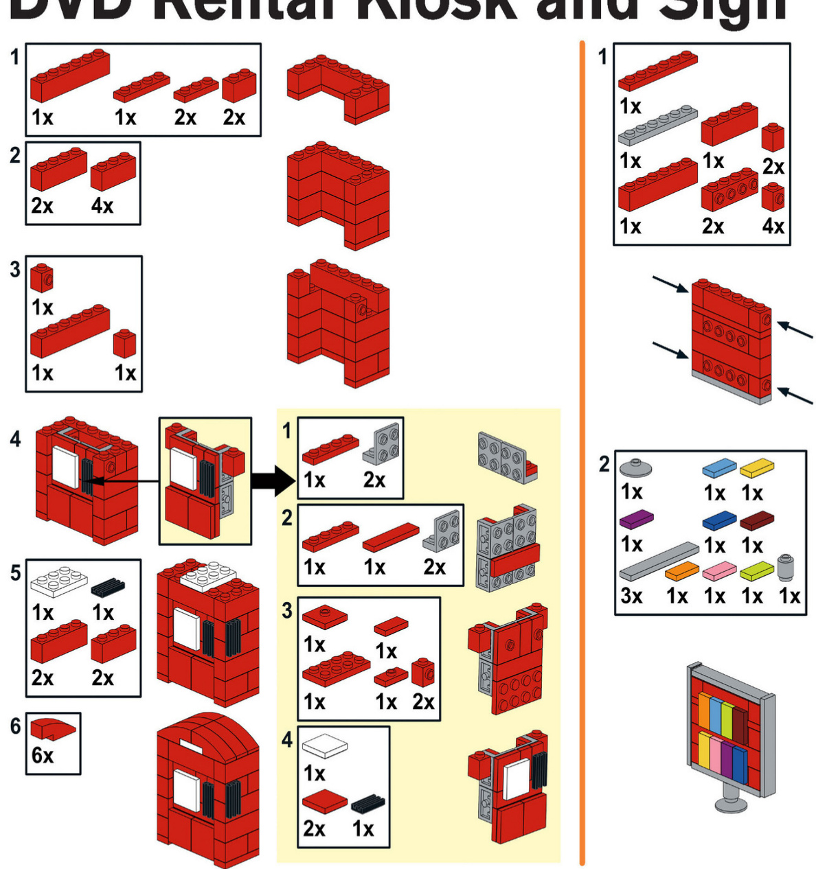
Toy Store and Camera Shop
Our next stop is a toy store that shares a baseplate with a camera store.There are some interesting techniques used in both of these stores,so pay close attention.
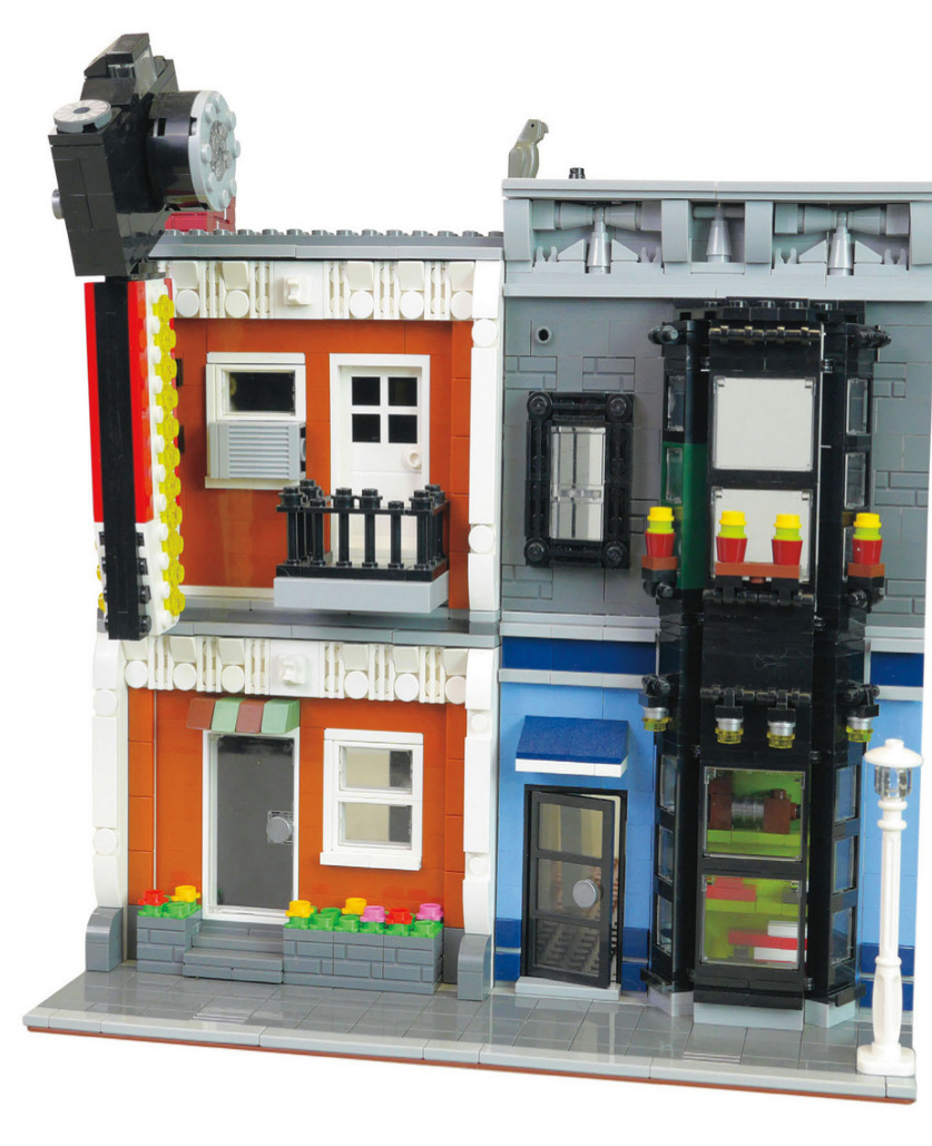
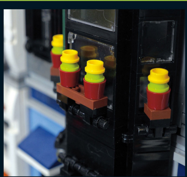
Thesesmallflowerpotslinethesecond-storywindowabovethe toystore.Theseplantersprovideasparkofcolortocontrast againsttheblackwindows.
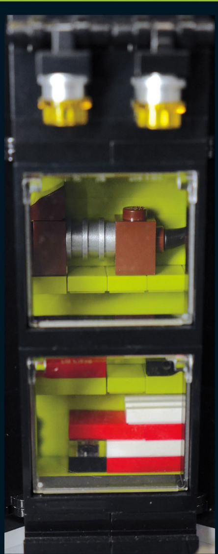
The toy store’swindowdisplay showsoff a slinkydog,somecars,andafiretruck. Childrenwill justhavetogoinsidewhen theyseethatfromthestreet.
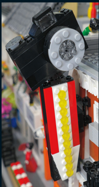
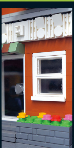
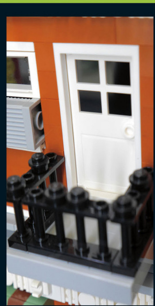
The sign with a yellow arrow and flashing lights helps draw in customers to the camera store once the sun goes down.
This building was made using SNOT techniques. The lower level is built upside down, including the stairs and the flower boxes out front. The windows are built sideways.
This balcony juts out from the building and has a door that saves space by opening inward.
Japanese Restaurant andE Board Shop
AJapaneserestaurant and board shop make up the next set of buildings.
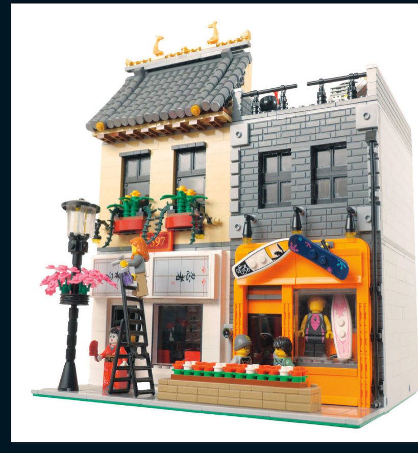
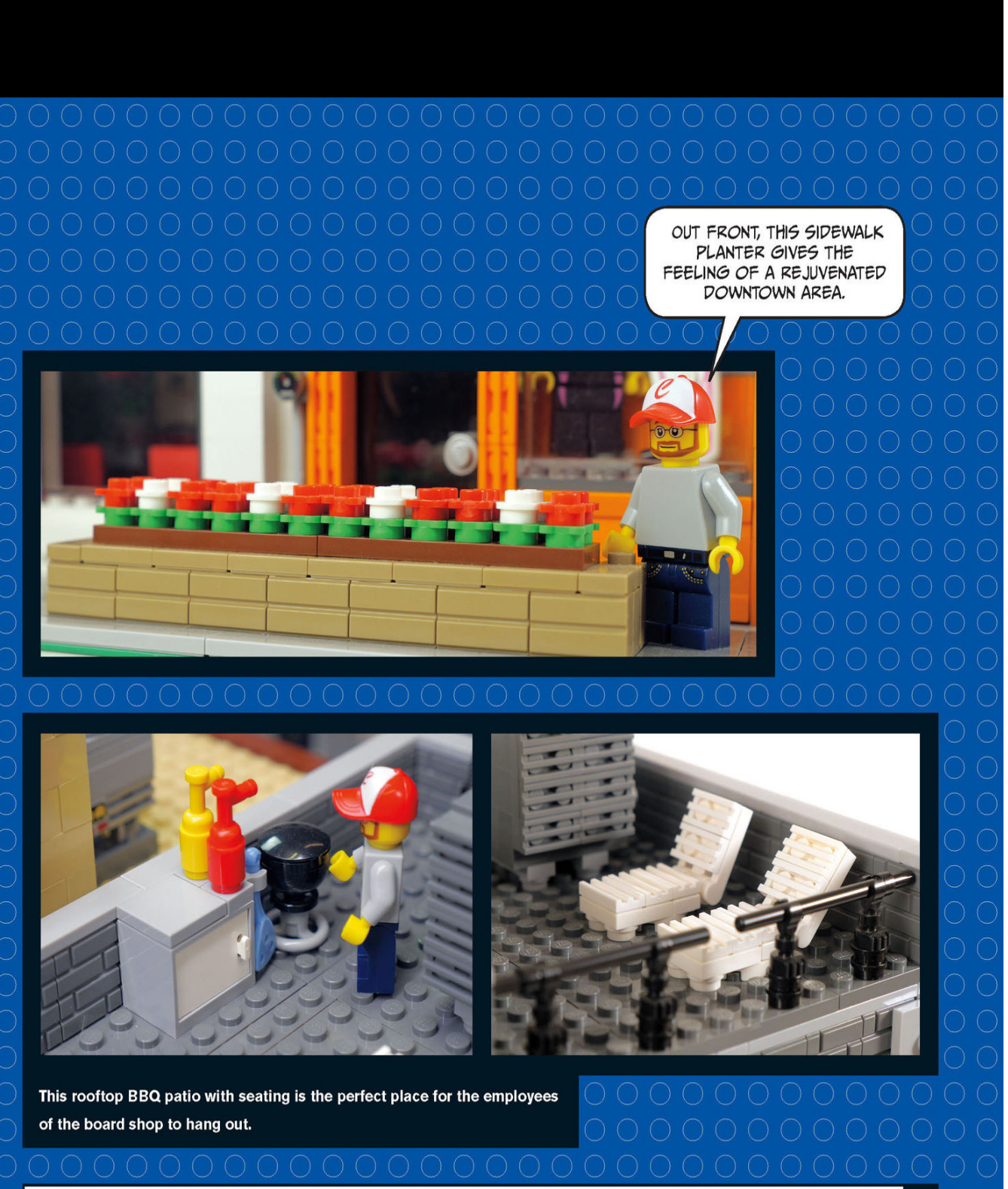
A COMMERCIAL NEIGHBORHOOD
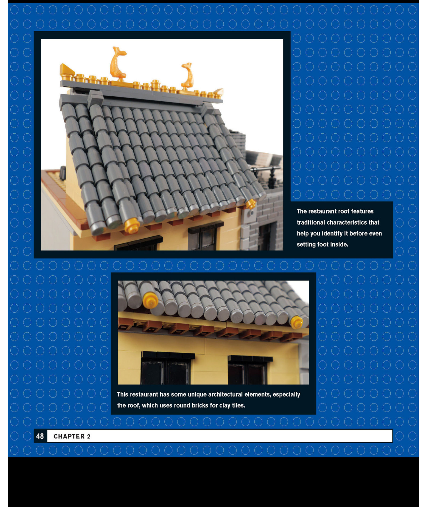
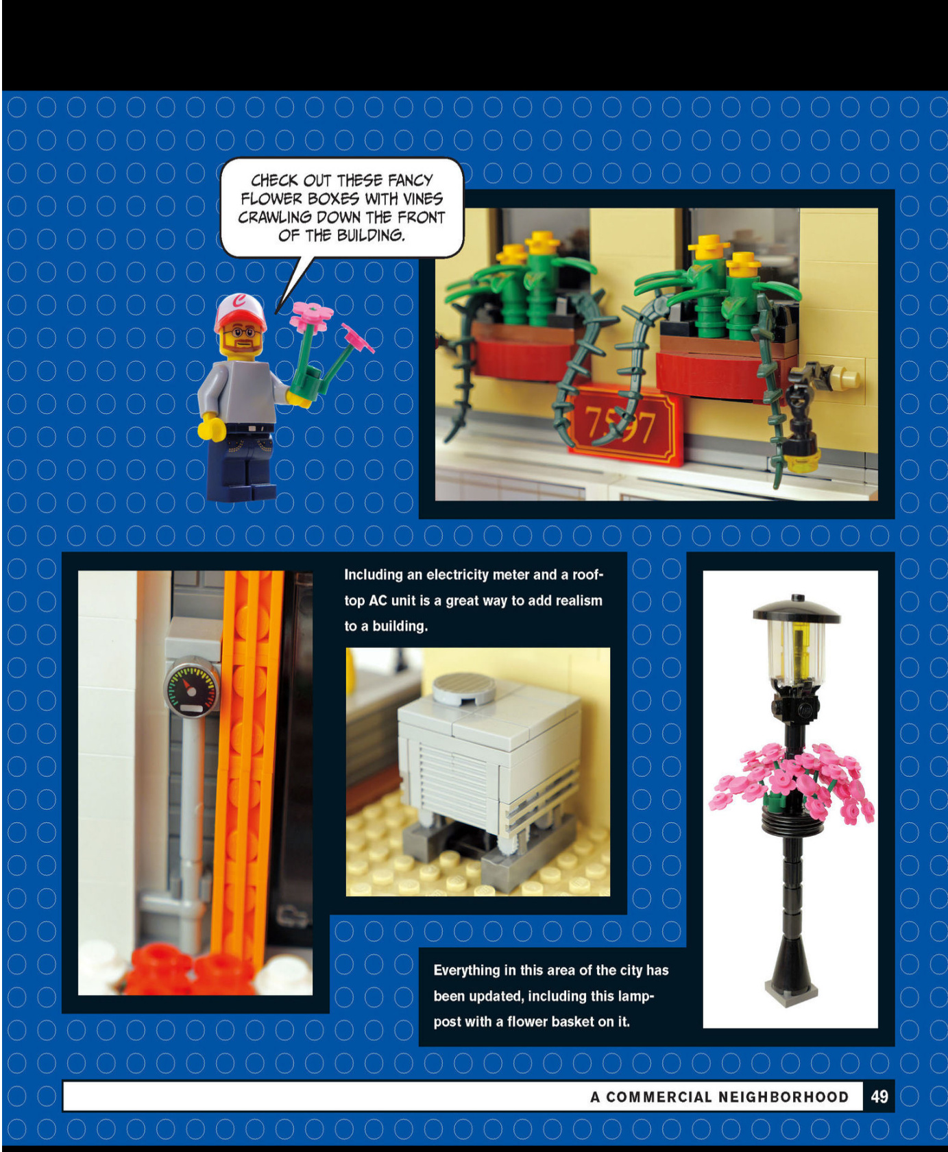
Board Shop Interior
Various fixtures inside the board shop give it a realistic look.

Here is the corrected text with proper spacing:
These display lights even include wiring.
Find creative ways of displaying the store’s merchandise, such as this rack that holds snow goggles. What other accessories fit in those sloped grate pieces?
Japanese Restaurant Interior
Aswe step inside the Japanese restaurant,we immediately see that the décor and furniture fit the theme.

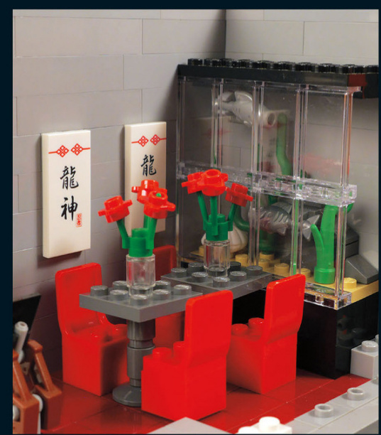
This restaurant has an aquarium and some Japanese tiles on the wall for decoration, and those chairs with silk slipcovers are a nice touch.
Ice cream shop
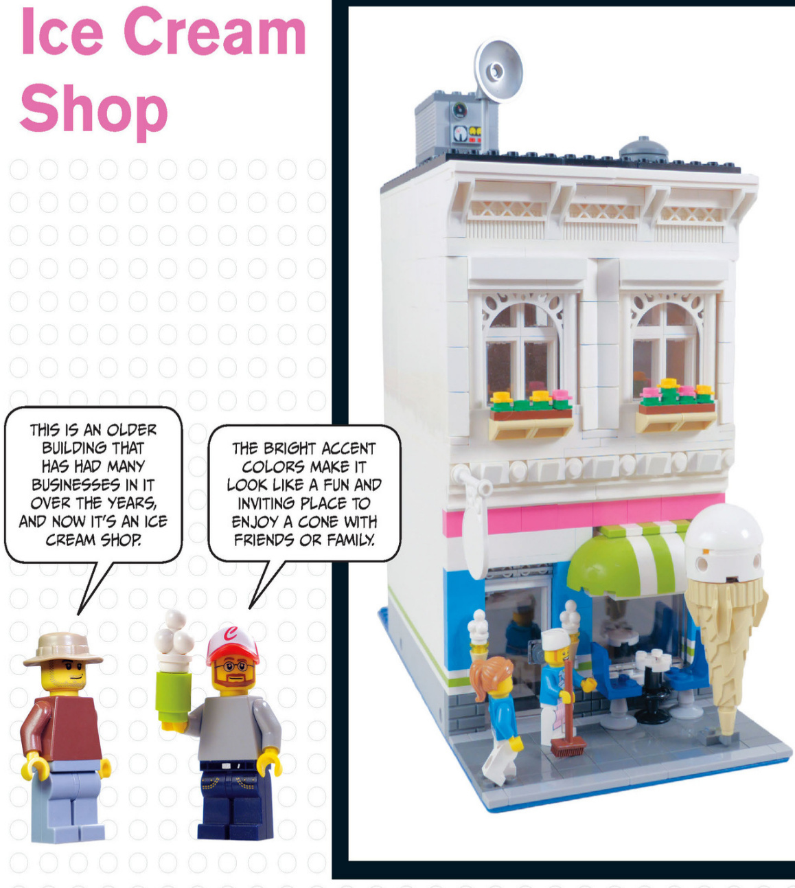
The ice - cream shop has outdoor seating for warm days.
These white pieces help create a fancy trim around the windows.
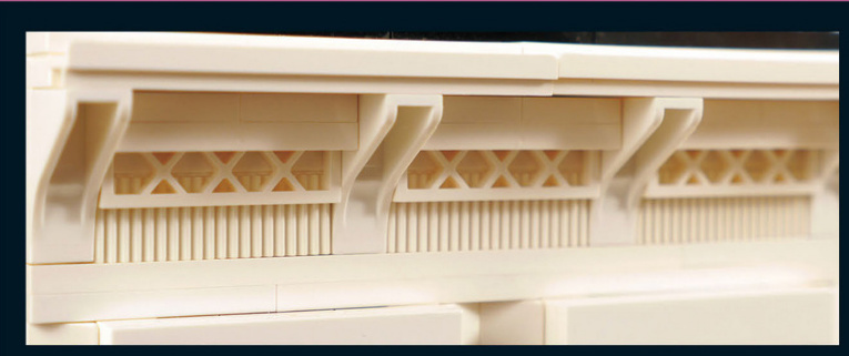
The arches and fences form a fancy roofline to cap off the building’s facade.
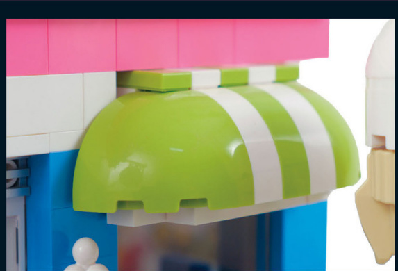
This awning was created to have two white stripes with a green stripe between them. Offsetting was used to achieve this effect and to center the awning over the window.
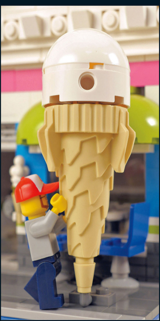
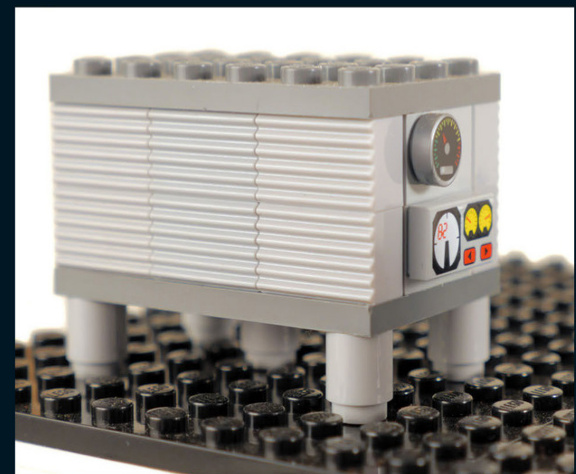
This huge AC unit means business and keeps the ice - cream shop nice and cold. A good way to research AC units is to look at rooftops on Google Maps to get an idea of how many or what sizes there are for different buildings.
This huge ice - cream cone draws in customers and leaves no doubt as to what type of shop this is.
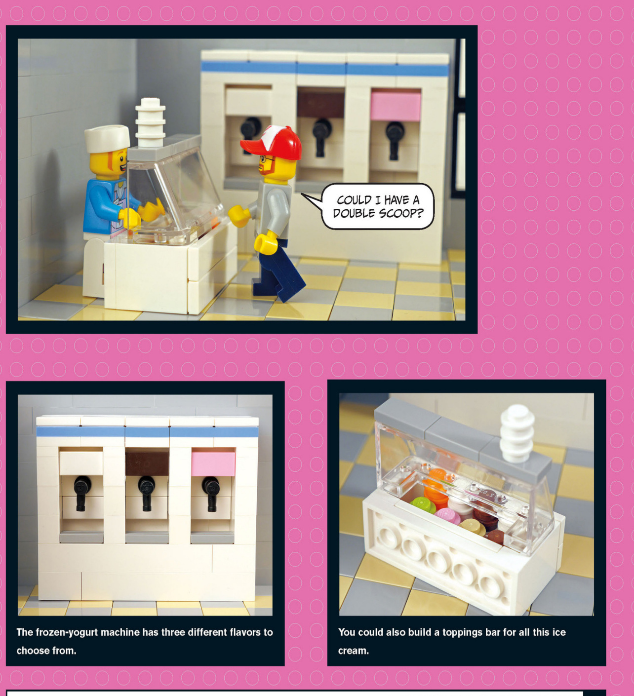
Toppings Bar
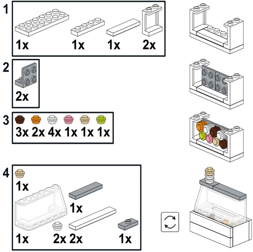
Small Vendor Stalls
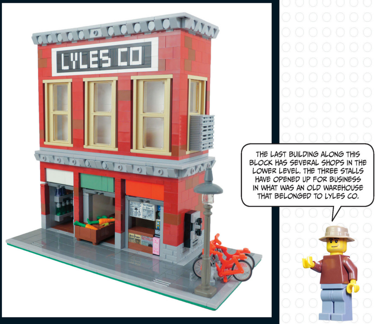
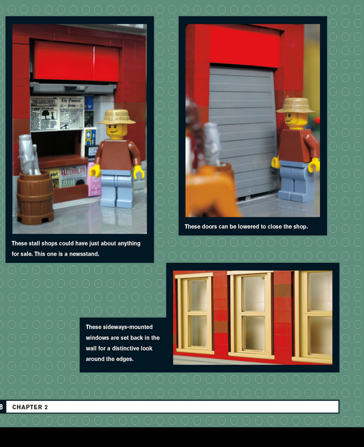
Window
Insert the window inside the frame and push until the window is flush with the front of the building. It will be sticking out in the back, as shown in the third image.
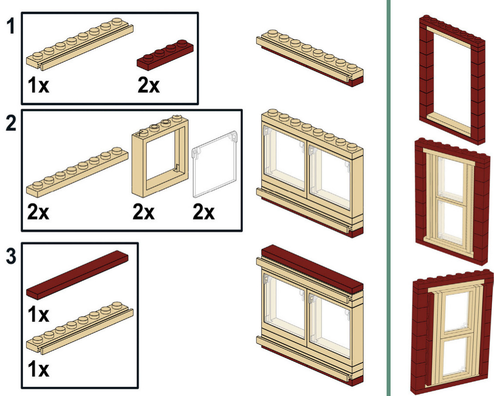
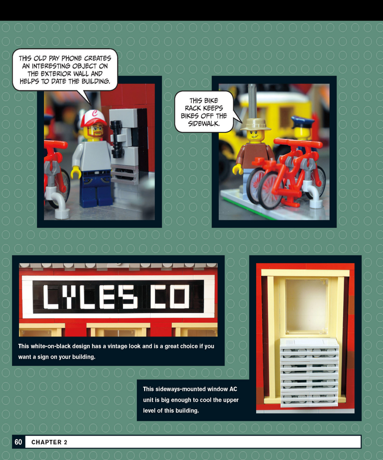
Caribbean Restaurant
The next stop on our tour is this colorful Caribbean restaurant.It’s surrounded by palm trees to provide atmosphere.
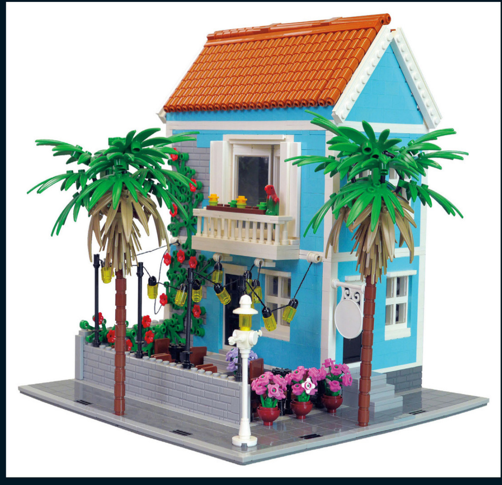

These hanging lights look great at night and provide ambience for the outdoor eating area.
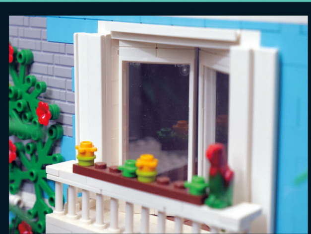
This second-story balcony features two inverted doors to make more space on the balcony itself. Hinges made it possible. The restaurant has ivy growing up the side with some nice flowers on it. It is easier to add the bricks with a stud on the side while you are building, so planning ahead is helpful if you want to add elements like this to your own walls.

All these rows of dark orange 1×1 round bricks make this clay roof look fantastic.
This palm tree mimics the look of a real palm with leaves of different colors. A black tube runs through all the round 1×1 bricks to make the tree trunks sturdy.
Don’t forget to add some color and vegetation to your sidewalks.
Parisian Corner Café
This beautifully crafted Parisian building is loaded witharchitectural details from a bygone era. It featuresarestaurant and a shop on the ground floor.
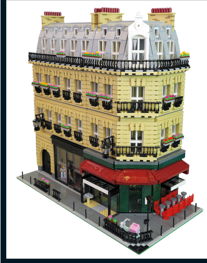
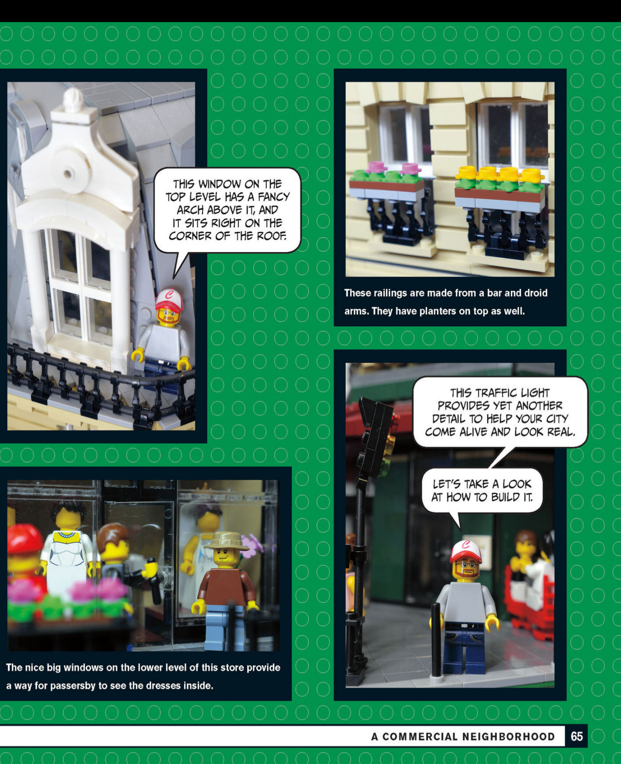
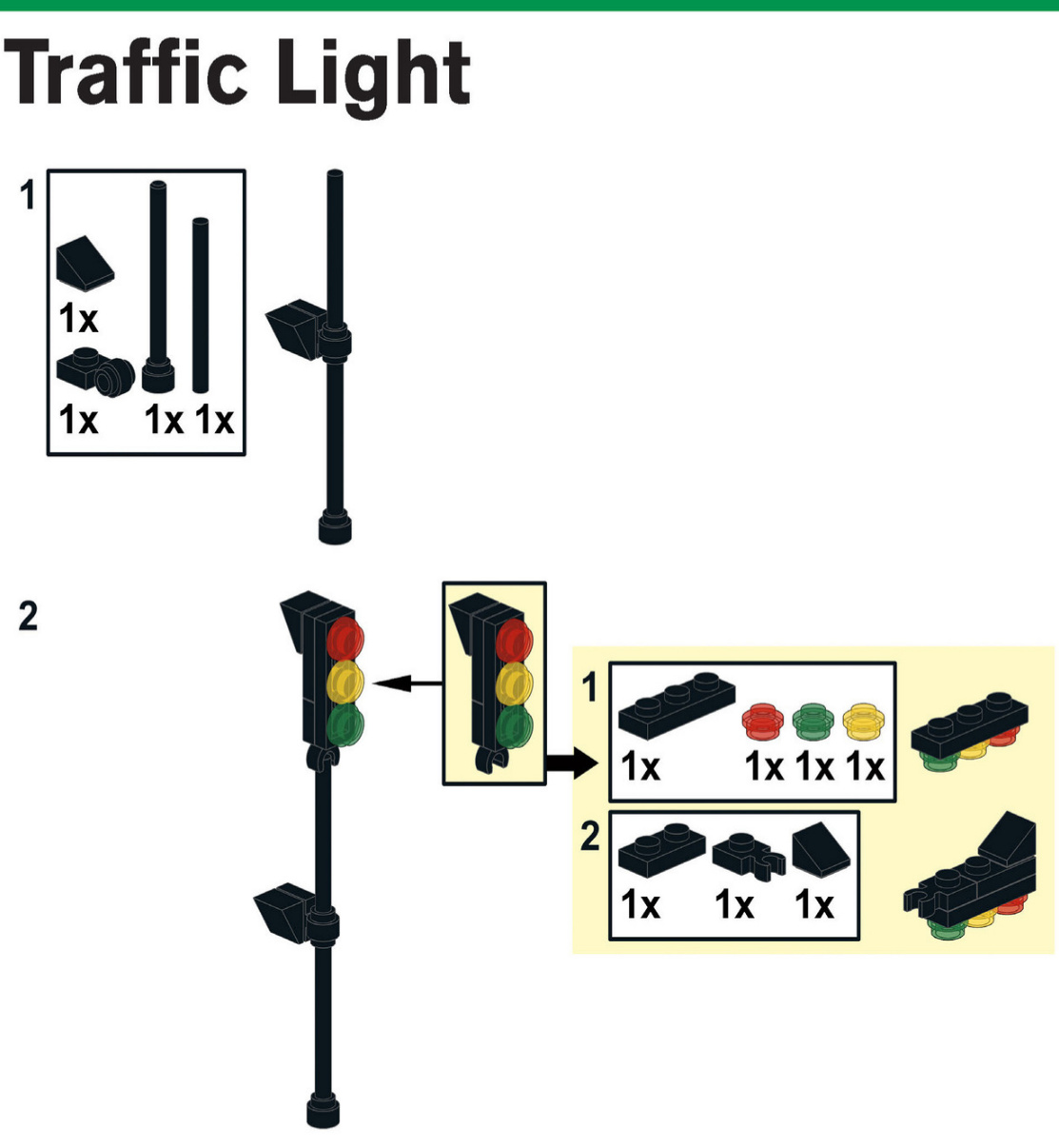
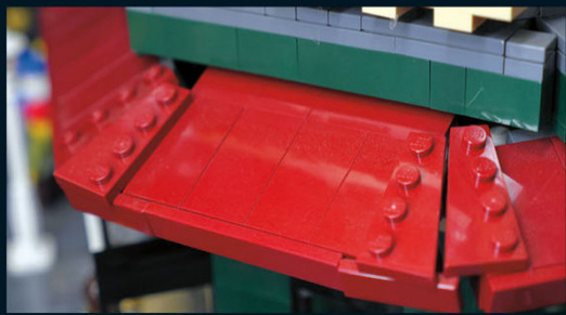
Here is a closer look at the corner awning. It wraps around the corner with the use of wedge plates.
This roof has a curve to it, just like many of the buildings found in Paris and elsewhere in Europe. Take note of the details above the windows and the railing that goes around the whole roofline.

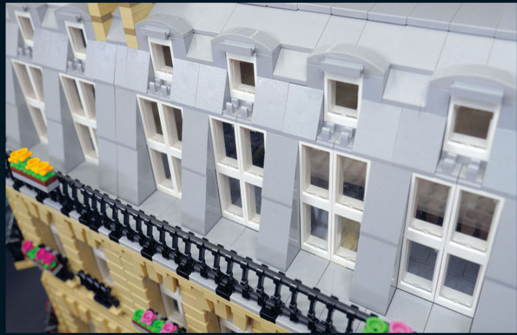
See if you can build this fancy lamp that hangs off the side of the building. Those are window panes from 1×2×2 windows.
What would a restaurant be without seating? This one has tables outside so that the patrons can enjoy the nice weather.
ACOMMERCIAL NEIGHBORHOOD 67
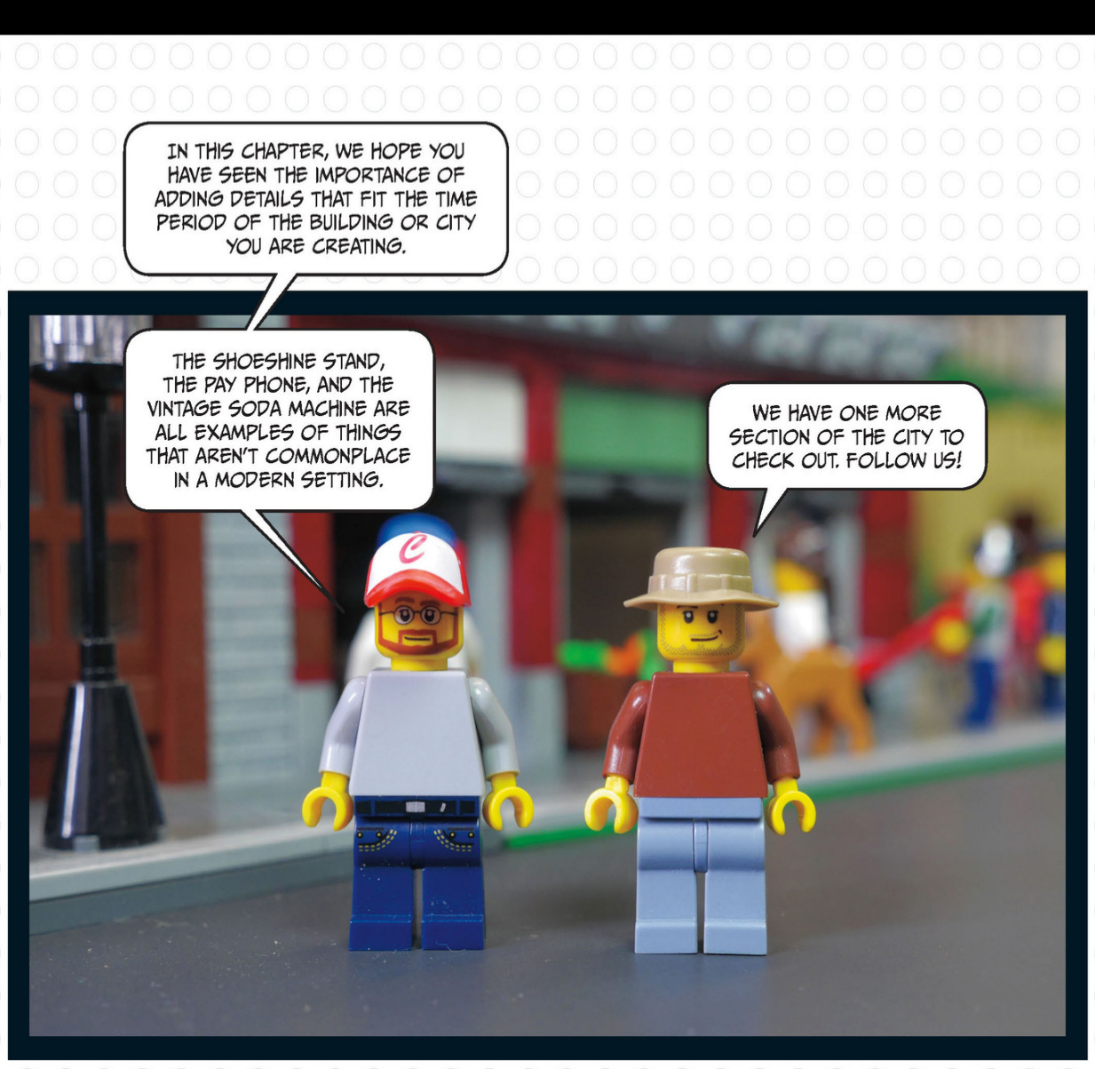
Public Places
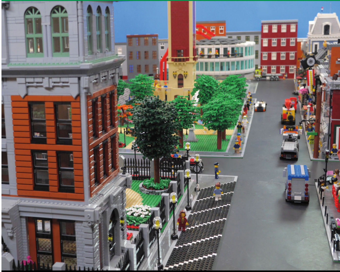
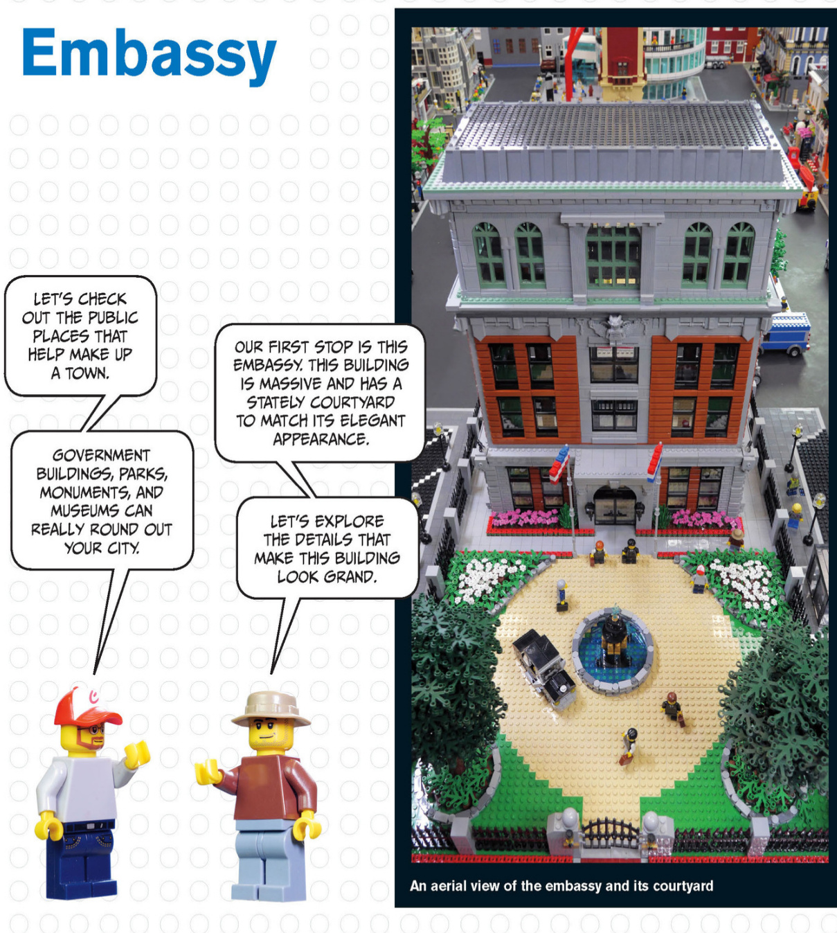
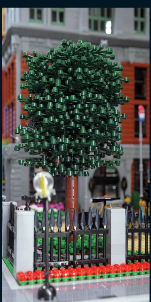
Acoupleoftreesbalancethecourtyard.Thefoliageiscreatedfromstacksofleafpiecesarounda blackpipethat runsthroughthetrunk.
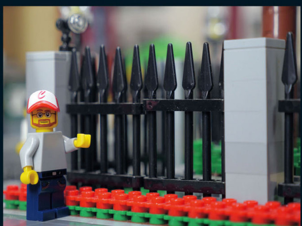
Thiswrought-ironfencekeepsunwantedvisitorsout.It’smadeof spearsandTechnicliftarms.
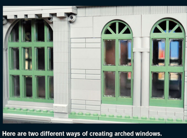
PUBLIC PLACES 1
This security-controlled iron gate is wide enough for cars to drive through.
An elegant fountain adorned with gold statues sits in the middle of the circular driveway. It creates a fancy centerpiece for the courtyard.
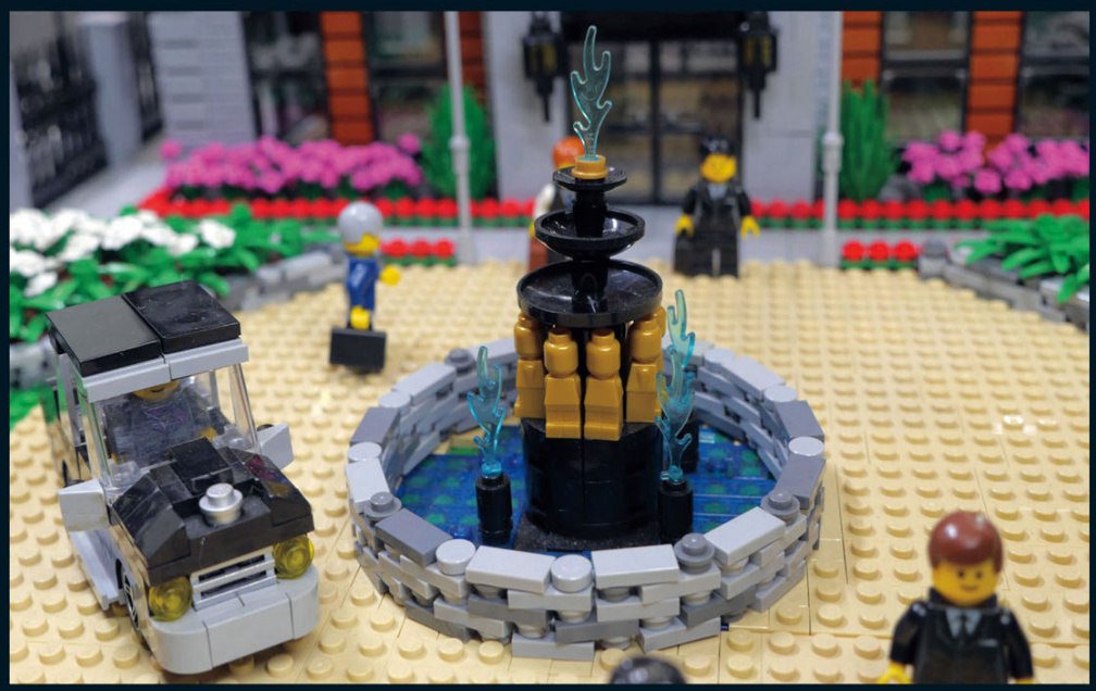
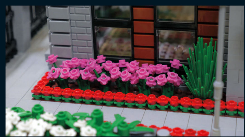
These flowers provide a spark of color against the neutral colors of the building.
I love the curved stone wall here. It really looks like it’s keeping the plants from growing out of the flowerbed.
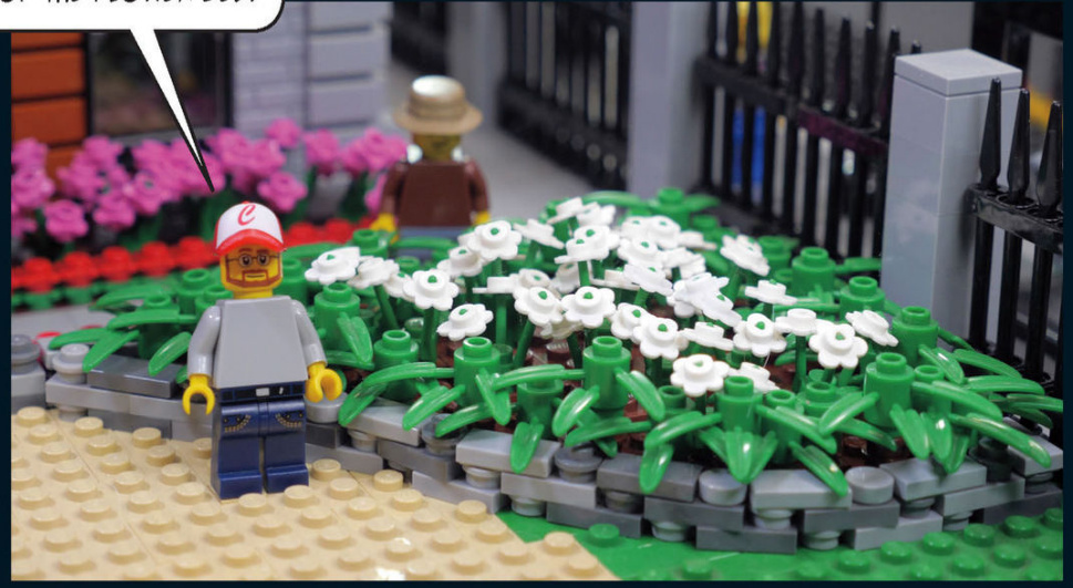
Embassy Details
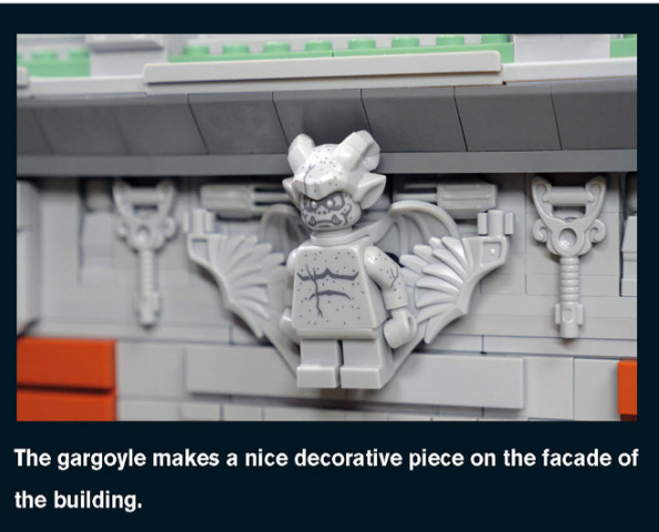
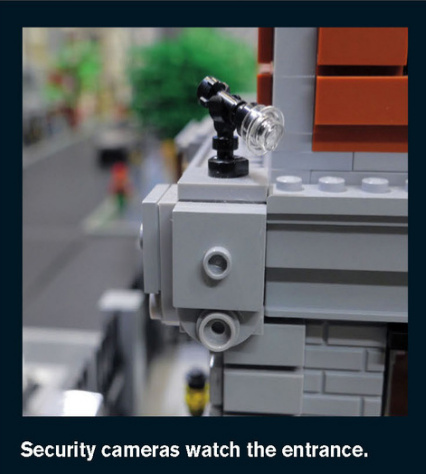
The exterior of the embassy features a mix of greystone and dark orange brick on all four sides. The symmetry of the facade adds to the elegance of the building.
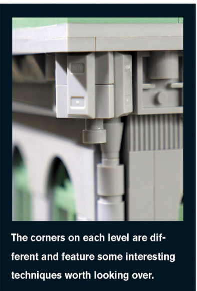
Brick City Park
This park features several sculptures, a small duck pond, and a large picnic area.Several trees outline the park’s boundaries.
NOWLET’SEXPLORETHEPARK,WHERETHE INHABITANTSOFTHECITYGOTOPLAYANDENJOYNATURE.
Park Details
You have almost endless possibilities for creating details in your own park.Athletic fields,basketball courts, picnic tables and pavilions,ponds,bridges, paths,and playgrounds will help create a realistic and beautiful public space.In this park, a small duck pond and mature trees provide city dwellers with a slice of nature.
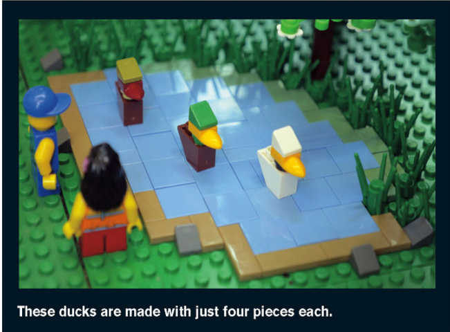
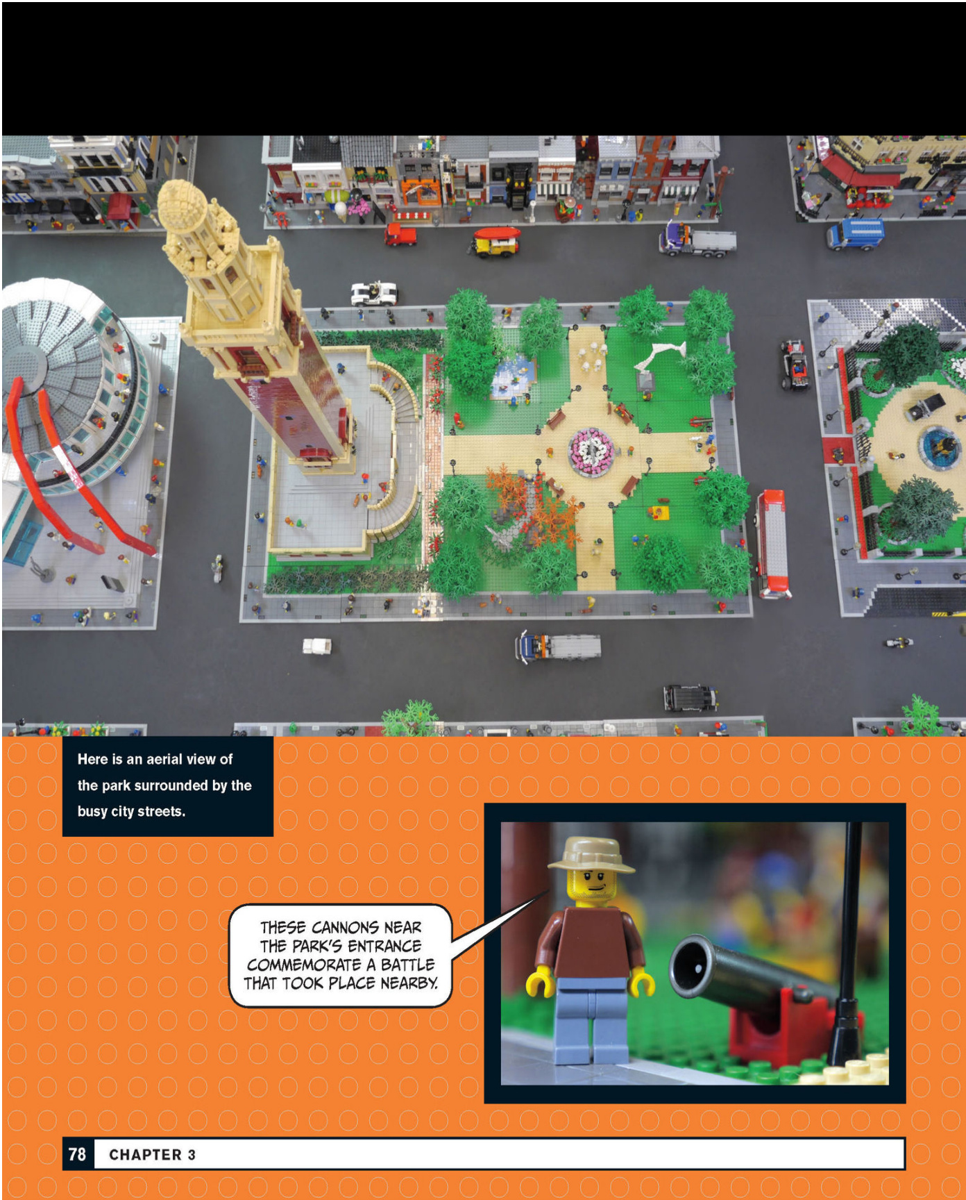
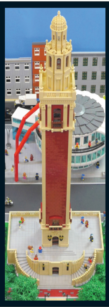
War Monument
The lower level provides a good foundation for the tower and has plenty of space for visitors to walk around and enjoy views of the park.
CURVED STAIRCASES WRAP AROUND THE FRONT OF THE MONUMENT ON BOTH SIDES AND PROVIDE SYMMETRY TO THE BASE.
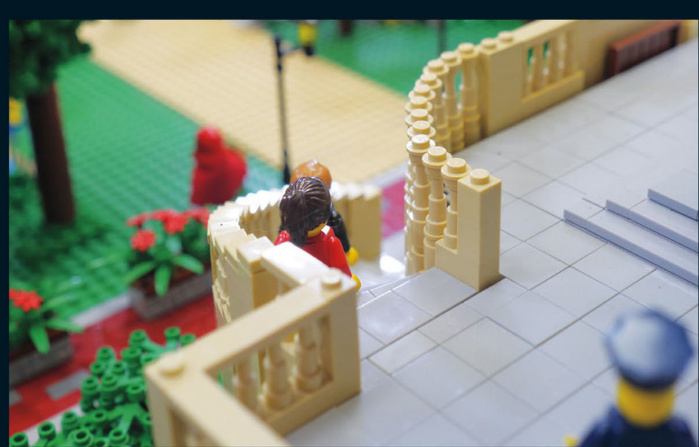
War Monument Details
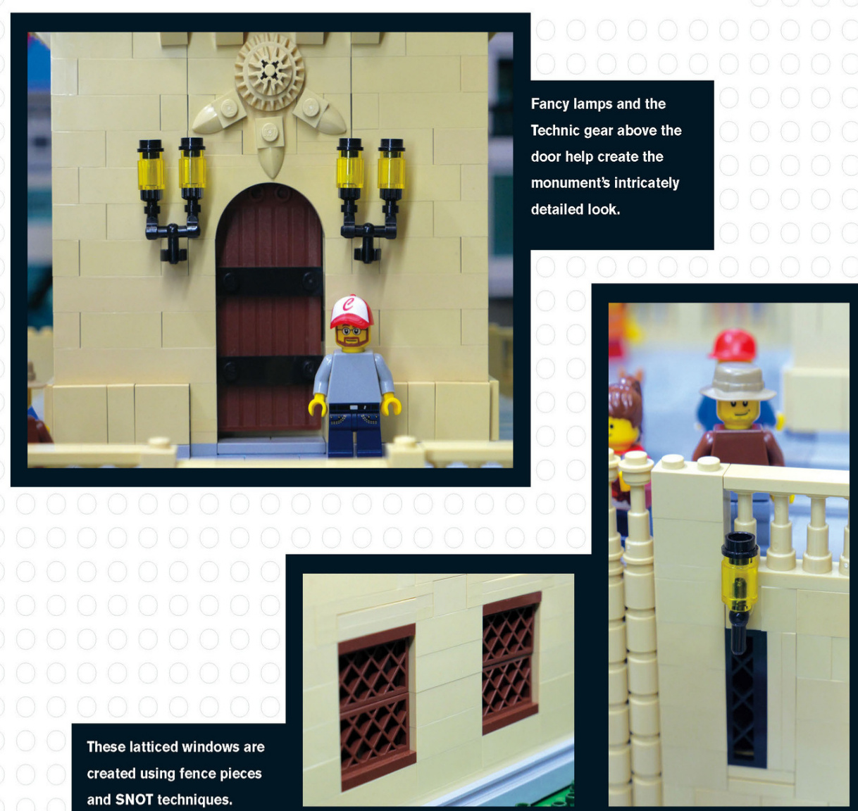
The Top of the Tower
Near the top of the tower, the architectural details are really packed in.Notice the railing and the columns on either side of the window.
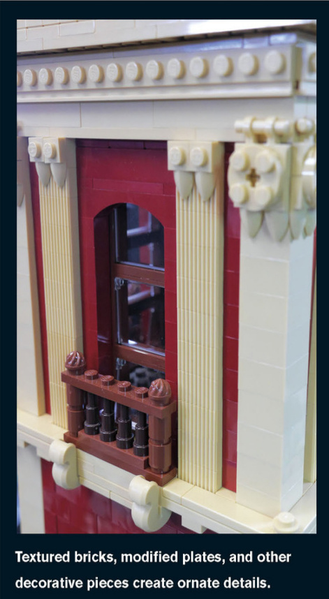
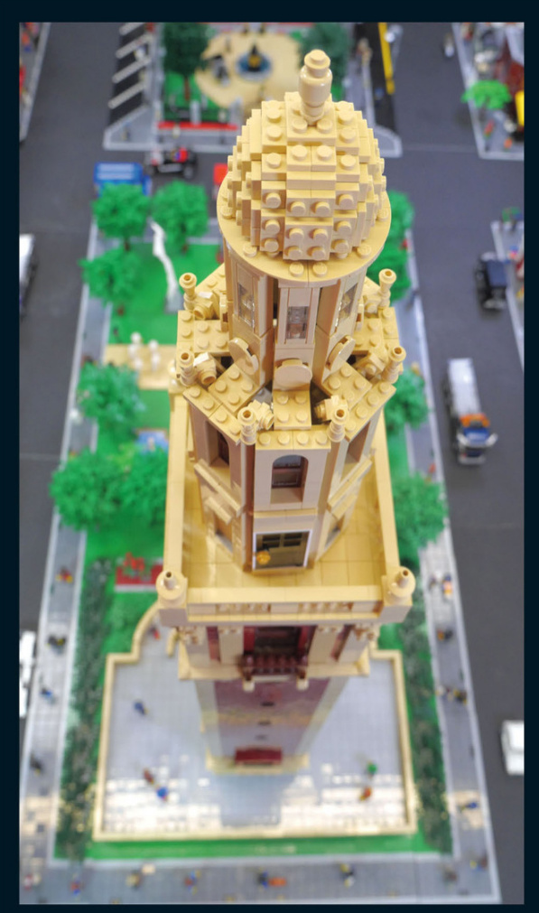
Take a minute to look over all the details around the top of the monument, especially the brick-built dome.
Art Meseum
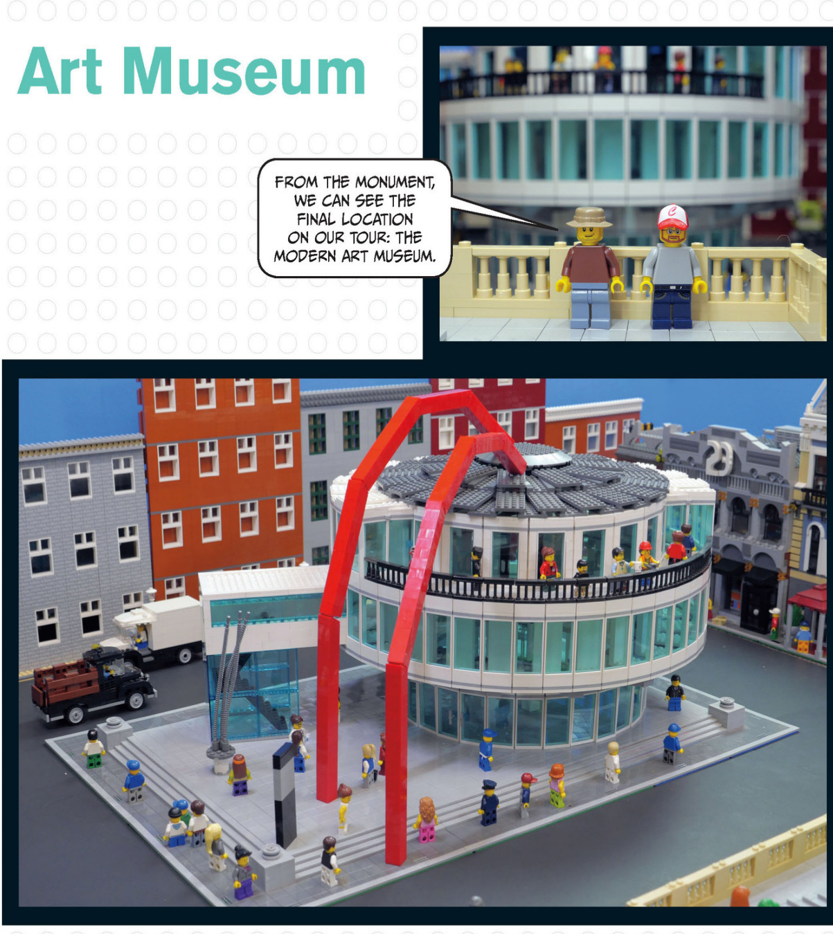
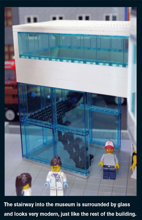
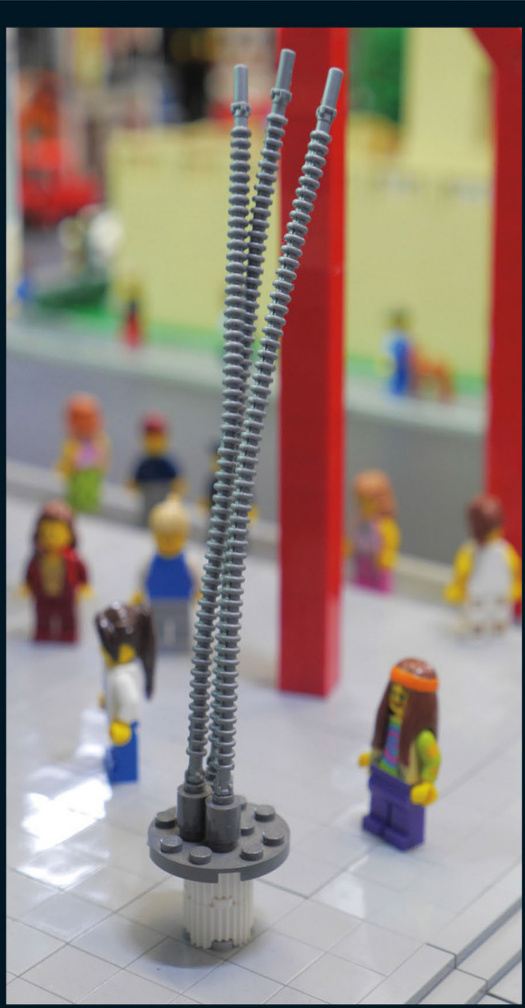
Thissculptureoutsidethemuseum’sentrancedraws invisitors.
Art Museum Details
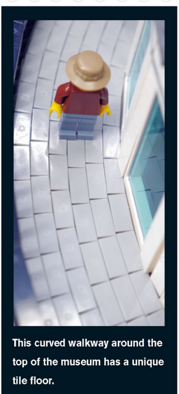
The biggest sculpture on display at the museum is part of the museum itself. The two red arms stretch from the ground to the top of the round roof.
Gallery
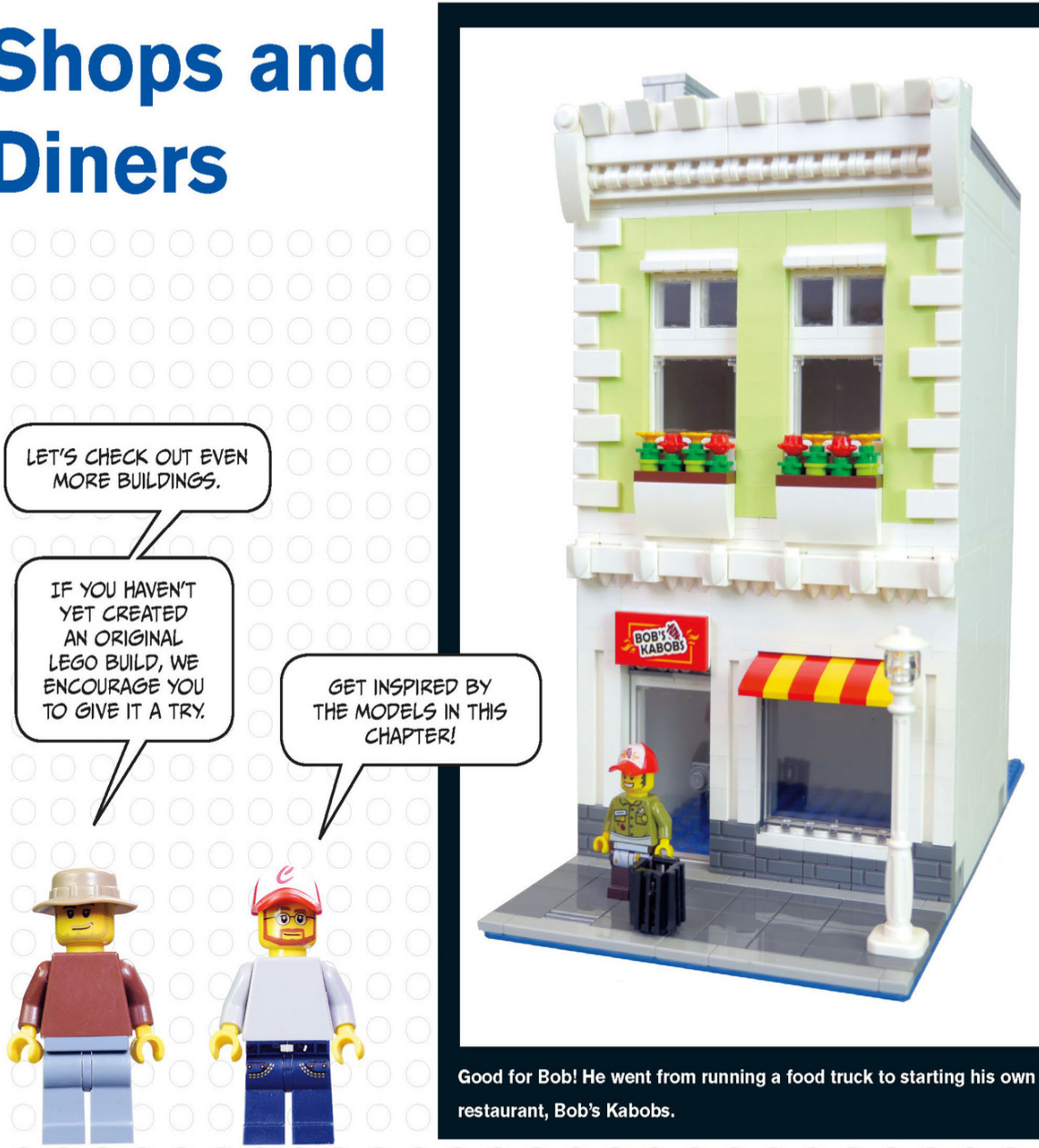
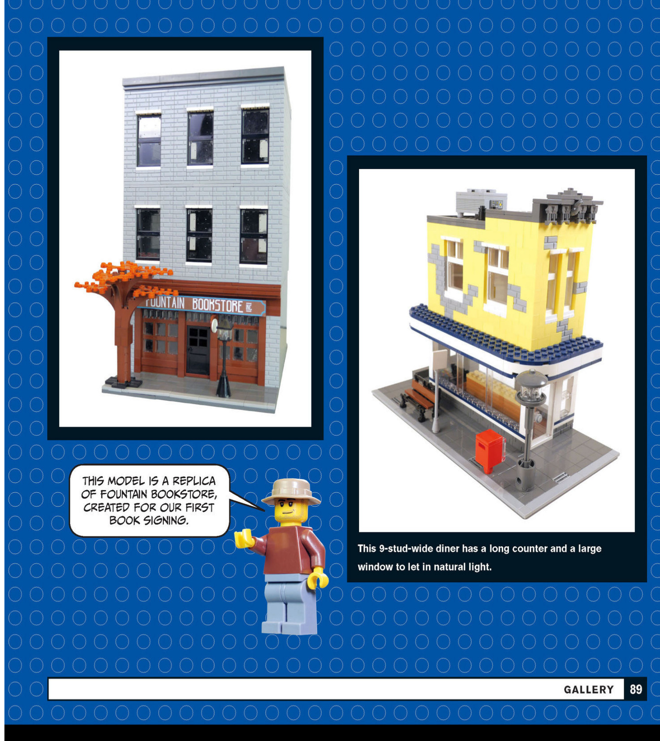
City Houses
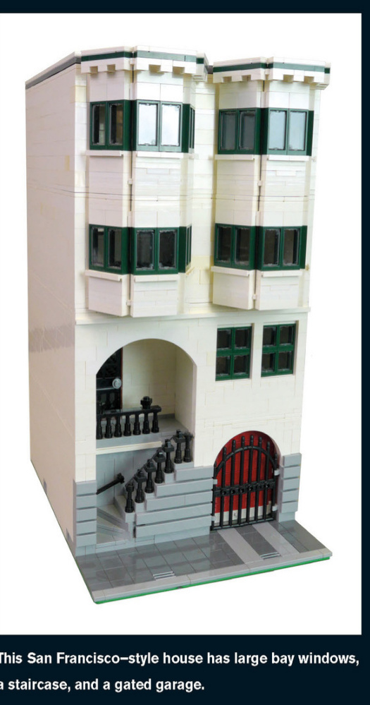
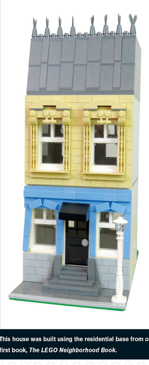
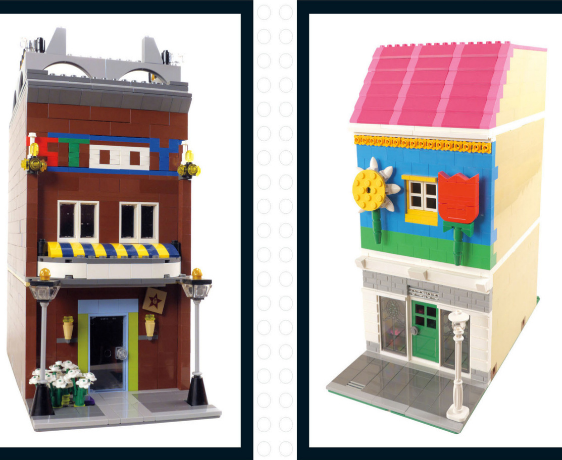
Whimsical Buildings
Think you just can’t do it? You can! These modular buildings were created by Jason’s kids.
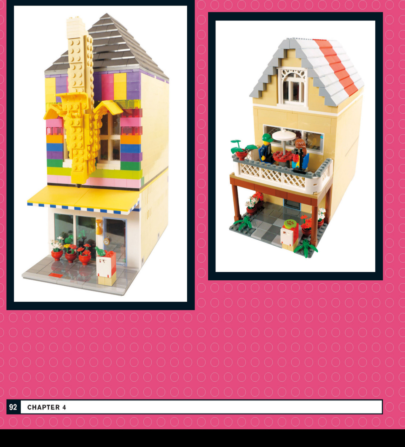
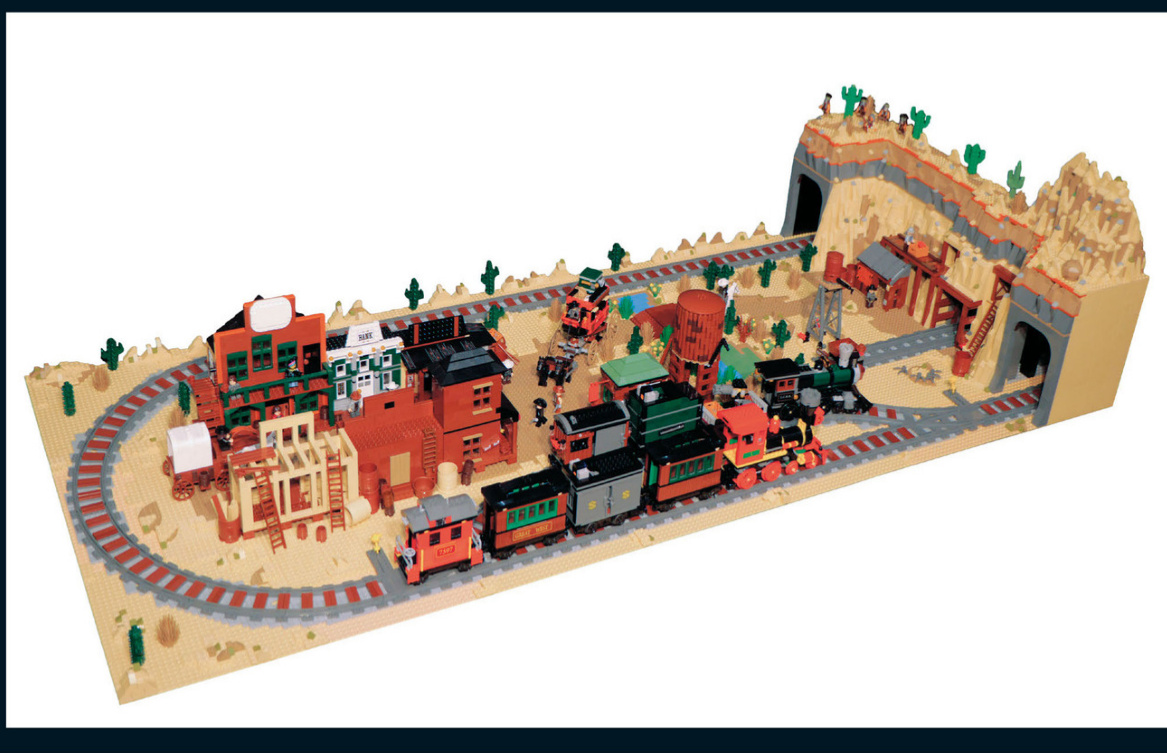
The WildWest
What other types of cities could you build using the techniques you’ve learned so far? Check out these examples of cities from differentplaces and time periods.The first is a small town from the Old West.
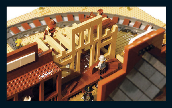
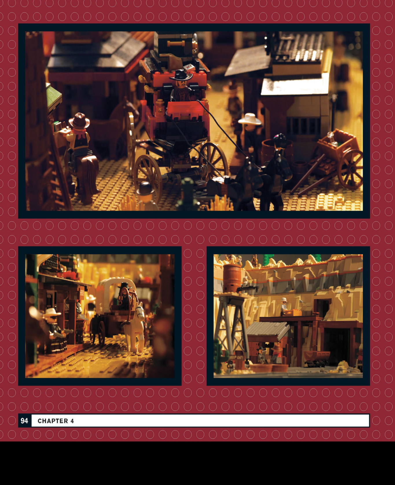
Ancient Persia
Minarets and markets abound in this model of a city in ancient Persia.
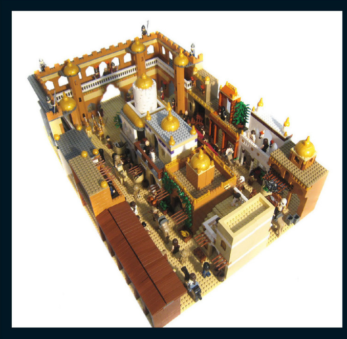
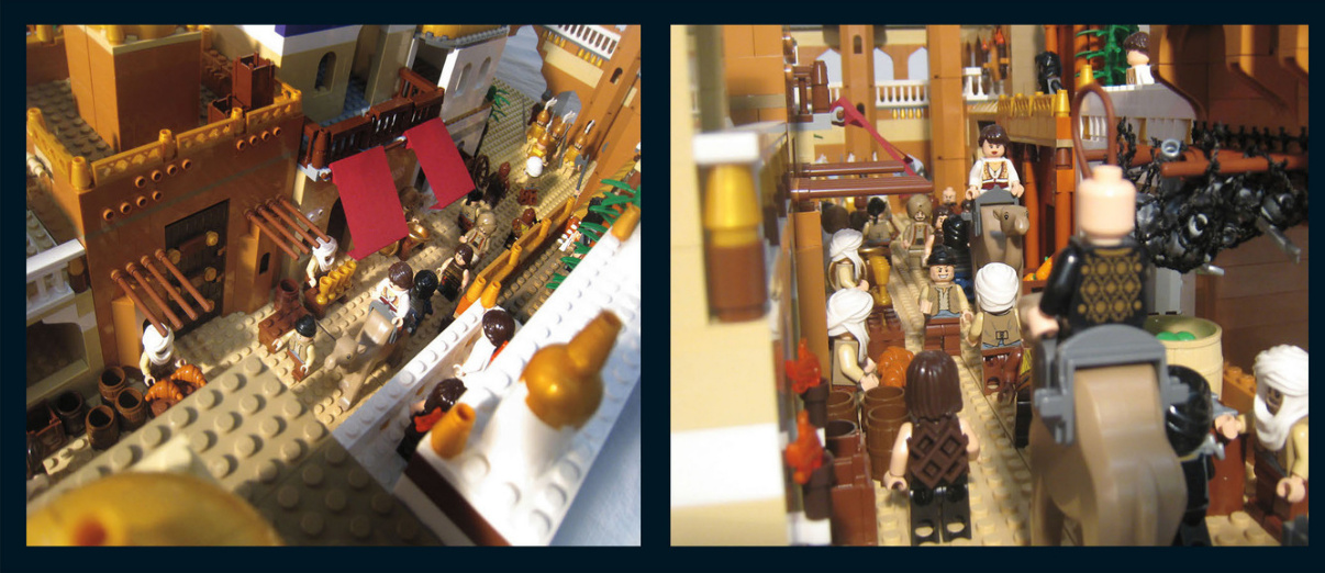
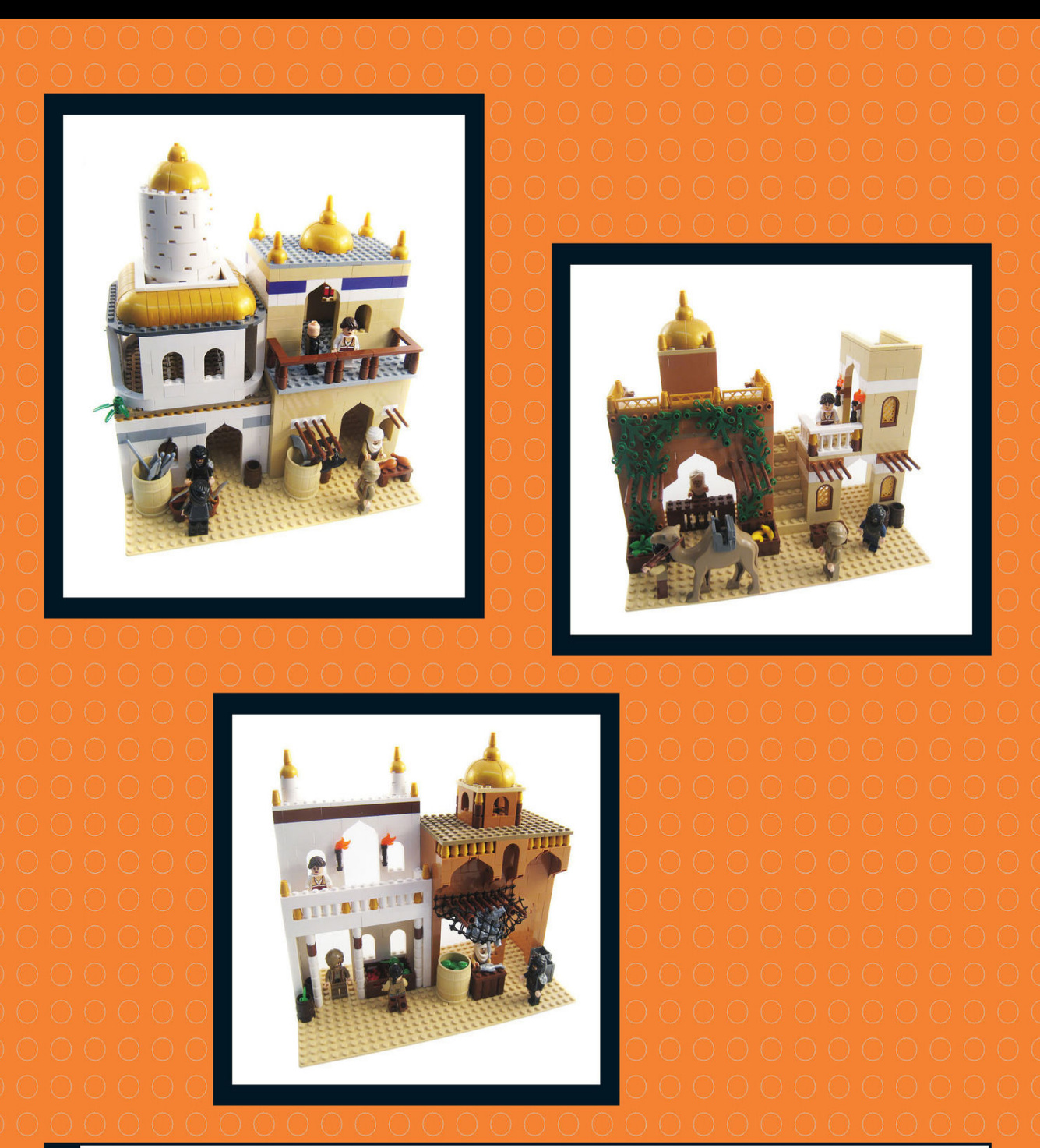
Caribbean
This Caribbean port city is packed with details from the Golden Age of Piracy.
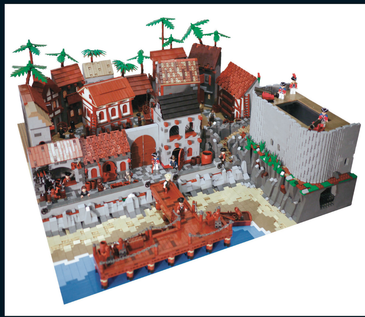
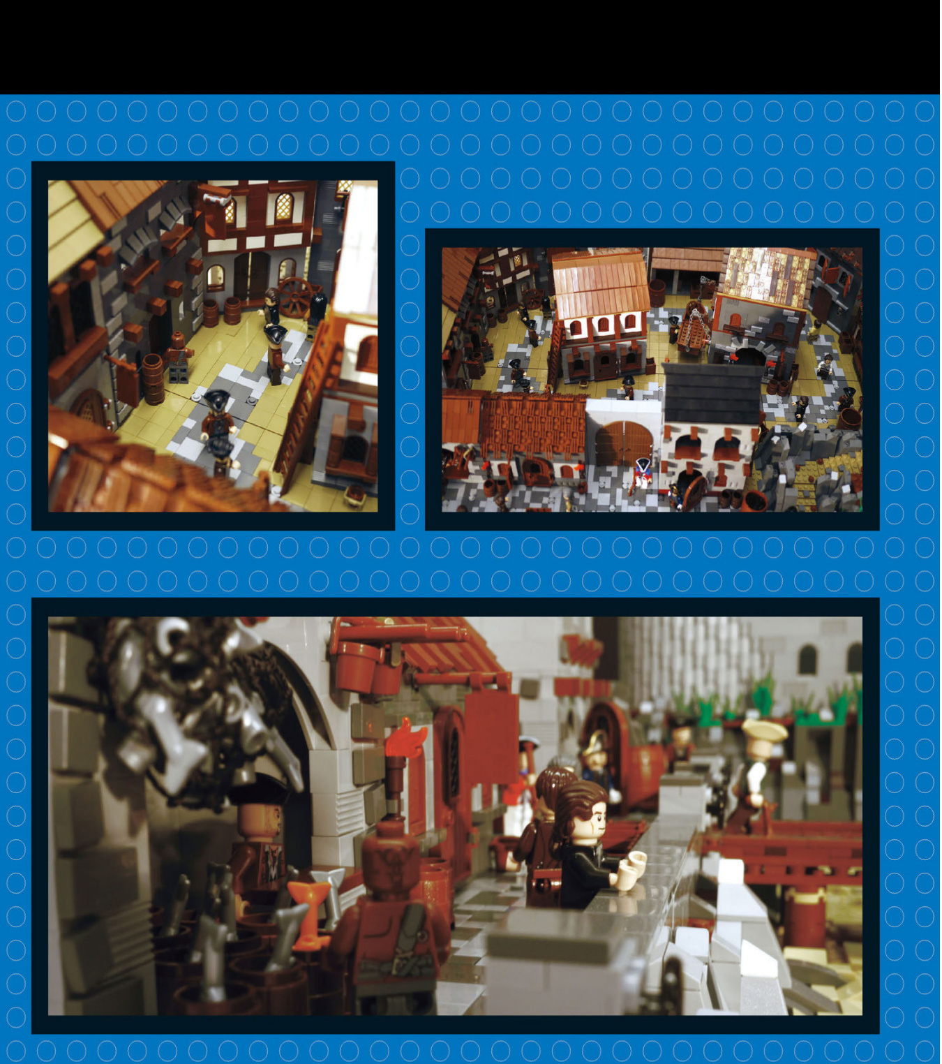
microscale city
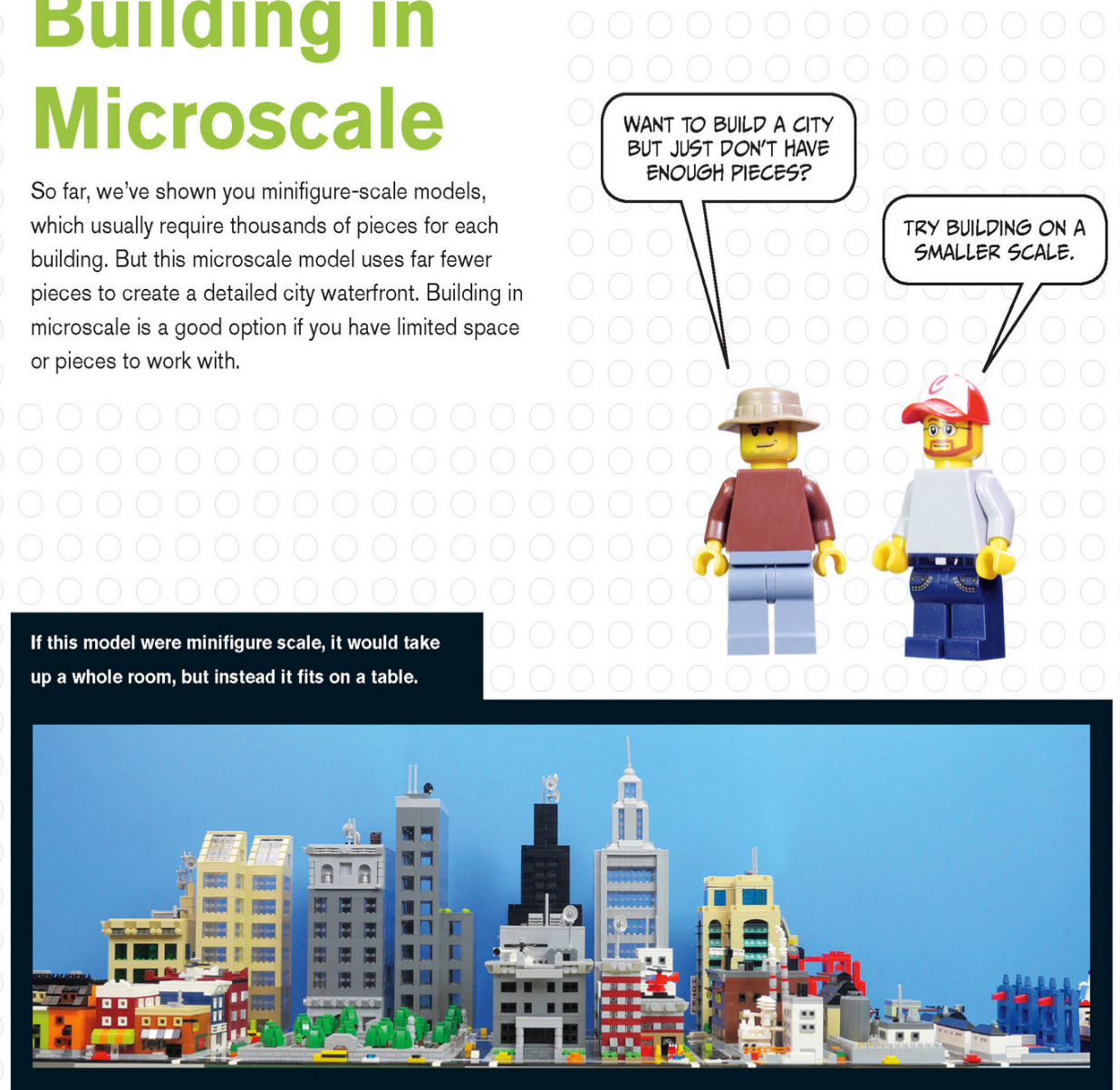
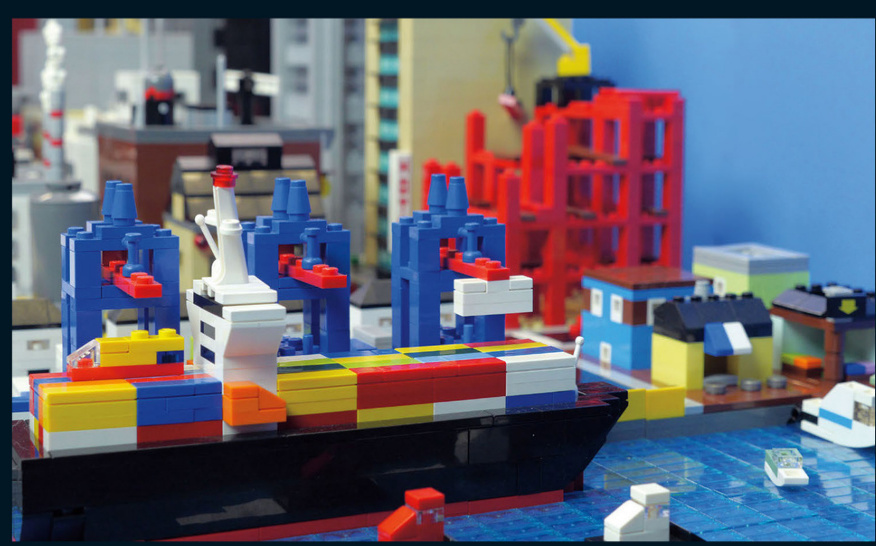
This port scene is made from basic bricks, tiles, and slopes.
Sky scraper scan be built with ease on this scale.
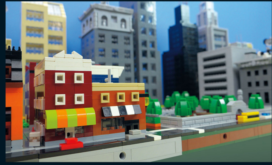
Creating models on a smaller scaleforcesyou to think aboutpieces differently.You must think about how you can createdetailswithfewer pieces and stillachieve the desired result.
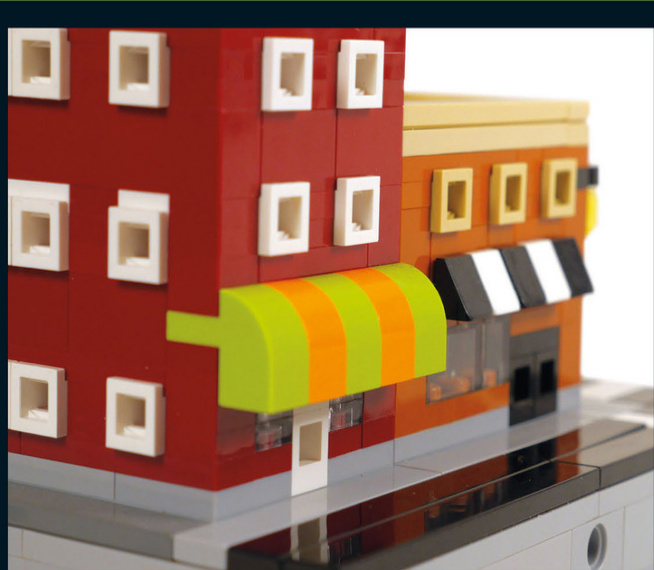
Aheadlightbrickturnedonitssidewiththebottomfacingout becomesa window.
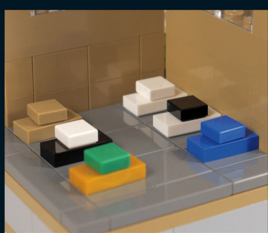
A jumperplatewith a1x1tileontopbecomesacar.
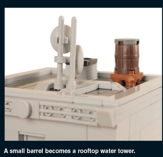
A Smaller Standard
Just as LEGO modular buildings have a“standard scale”of ,microscale buildings also have an informal standard.Microscale is a quarter of that size: Building at a consistent scale makes it easier for groups of people to combine their models into large city layouts at conventions, clubs,or meetings.
Take a lookat how thebase is built for one quarter of a city block.The most important details are the colors of the tiles that make up the street and sidewalk and the placement of the Technic bricks.Technic pins connect the bases together.
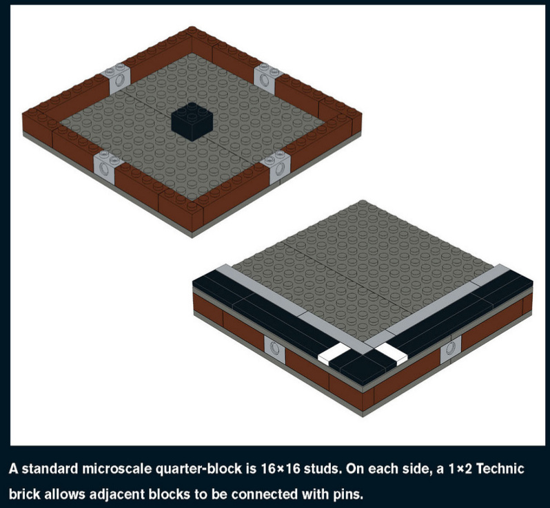
Emergency Services
This well-equipped fire station has a helicopter and aladder truck to put outfires.The green piecesare normally flowers,but here they are entire bushes.
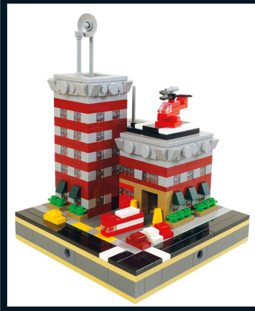
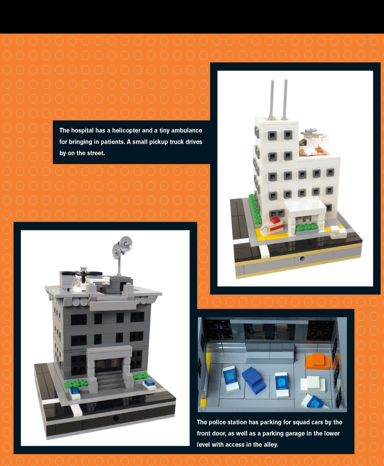
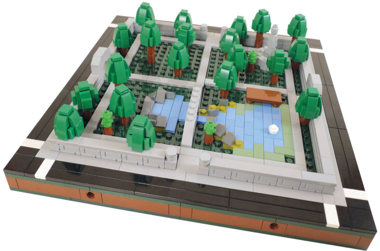
Park and School
These four sections connect to form a park.
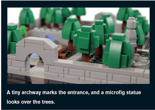
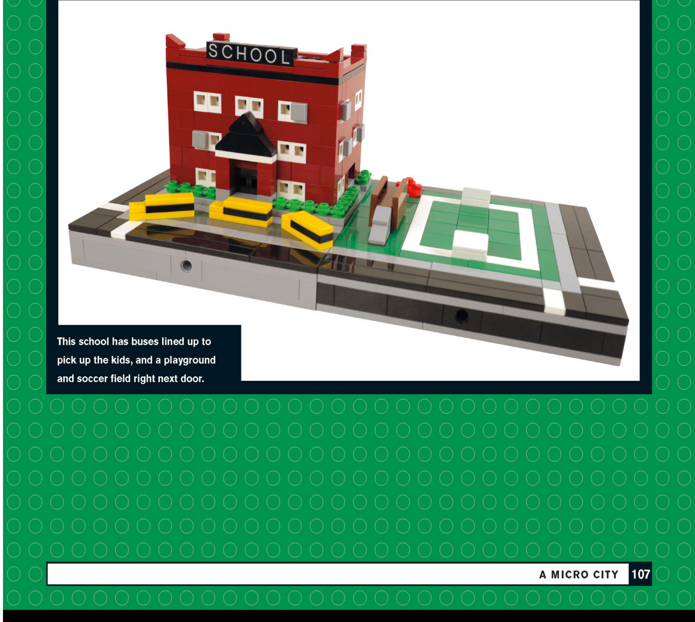
Neighborhood Buildings
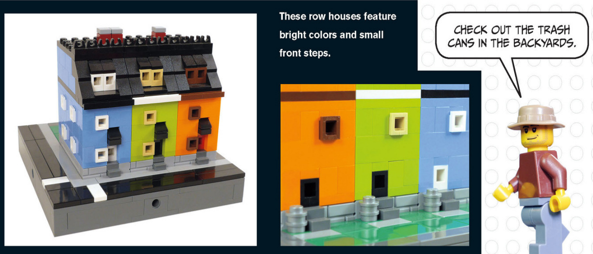
These shops have awnings and trim on the windows and doors. The dark orange corner store even has an advertisement on its side.
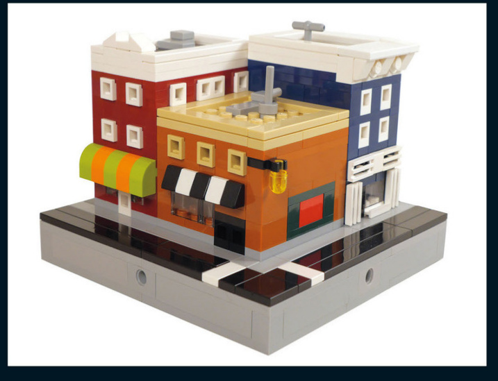
Office Buildings
This office building has some great details on the roof, such as AC units and communication equipment.
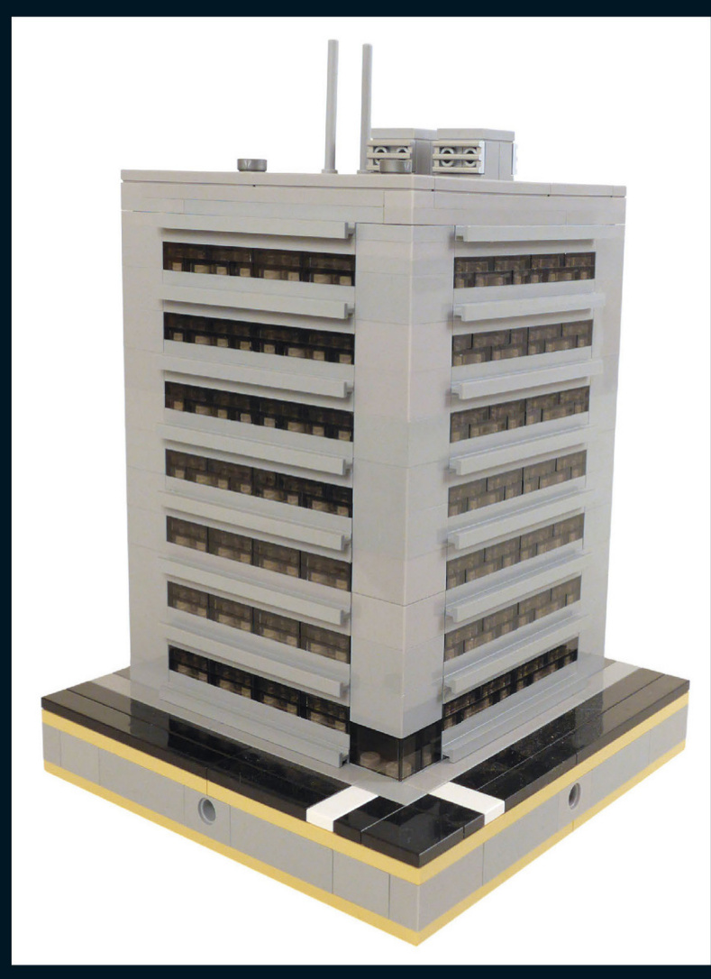
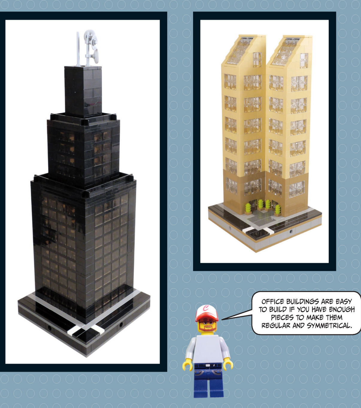
Factories
Sometimesllook at a piece and get inspired to create a building that uses it.That’s what happened with this weathered Octan sign.
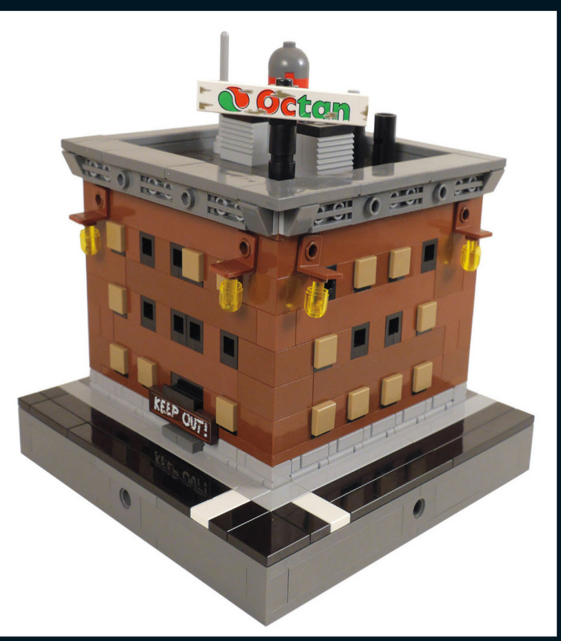
Thisoldfactoryhasboarded-up windows,signs,andeveldtimeygaslights.
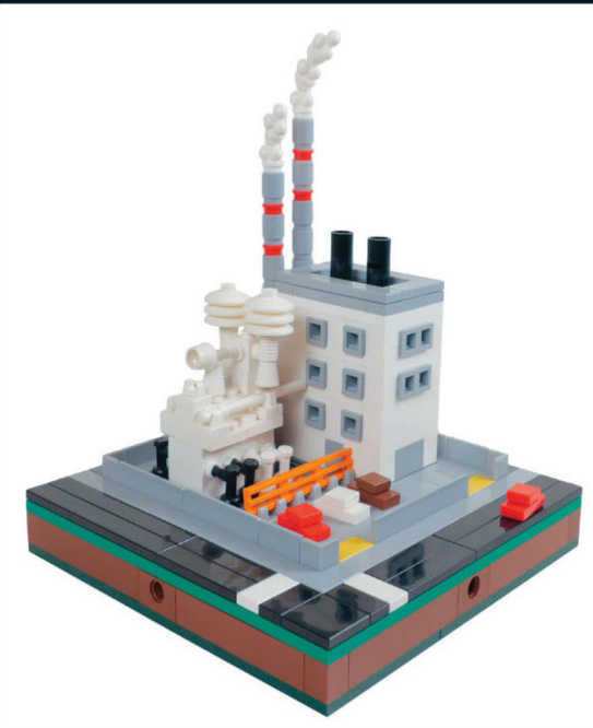
Thispowerplanthasalotoffundetailssuchasthe smoke,themetalfencingaroundthepropertyand theorangesafetybarricade.
Thisproductionfacilityhastwobigstoragetanks and somered warninglights.Check outtheroll-up garagedoormadeof1x2texturedbricks.
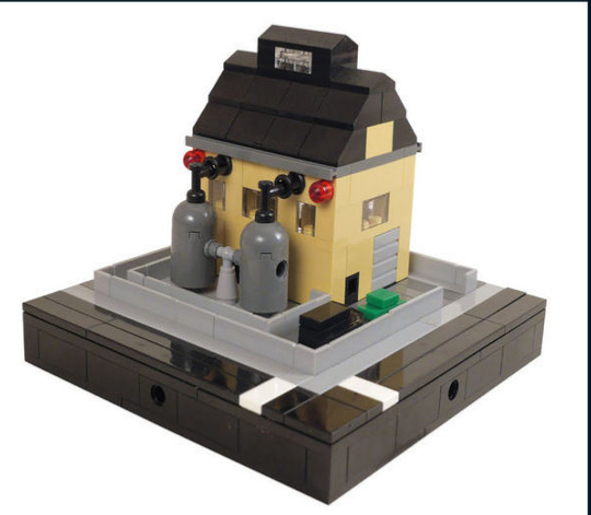
Commercial Buildings
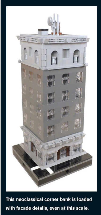
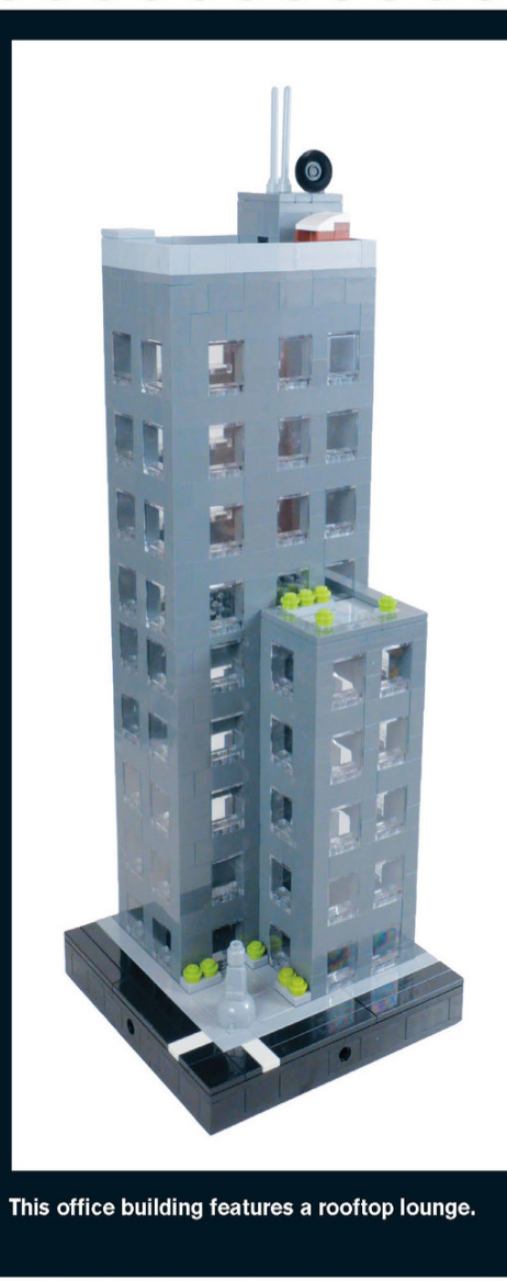
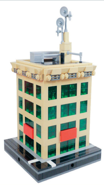
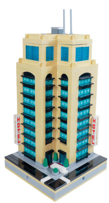
The roof of this newspaper publisher is loaded with communication equipment, as one would expect.
This deluxe hotel has a limo waiting by the door and a pool on the top level. The black 1×2 panels become balconies at this scale.
TRY USING TRANSPARENT COLOR BRICKS TO MAKE TINTED WINDOWS.
This building is under construction. It’s currently just girders with wooden walkways for the builders to get around. The mini - crane on top lifts pieces into place.
Skyscrapers like this one can be much bigger if you combine four 16×16 blocks and use the whole space to create a larger building.
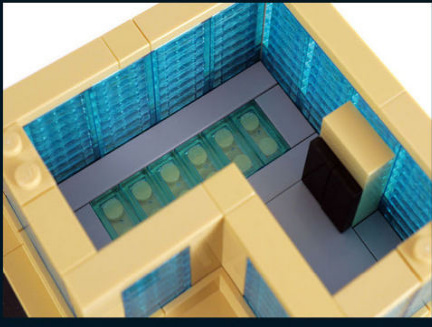
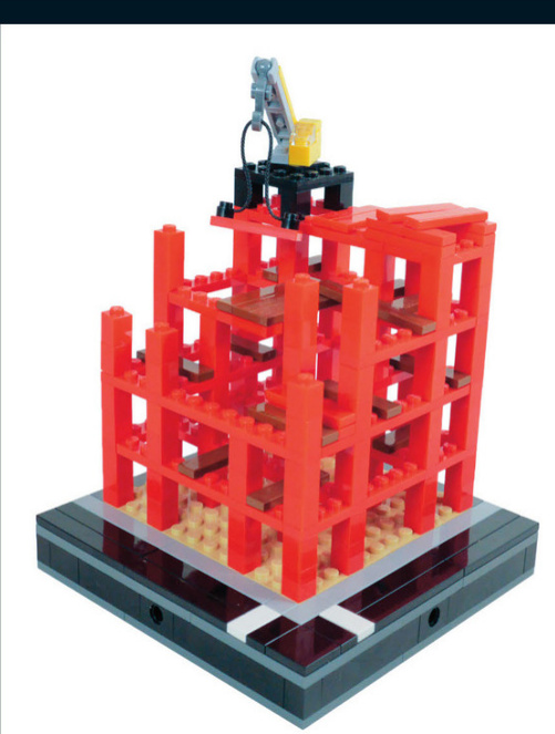
Thisbuilding isunder construction.It’scurrentlyjust girderswithwoodenwalkwaysforthebuilderstoget around.Theminicraneontopliftspiecesinto place.
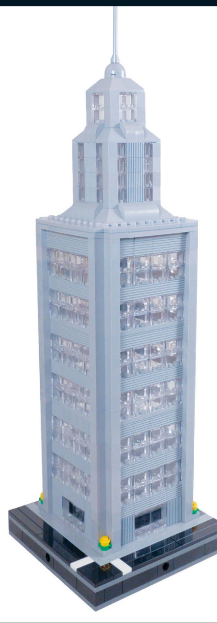
Skyscraperslikethisonecanbemuchbigger ifyoucombinefour16x16blocksandusethe wholespacetocreatealargerbuilding.
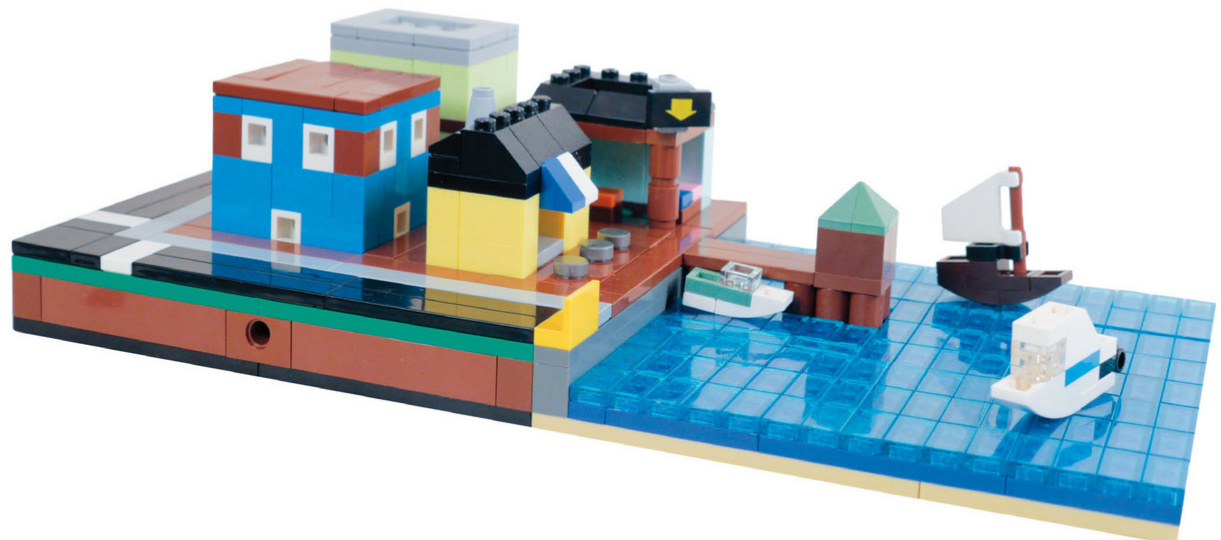
Harbor
Seaport shops line the bay,where tiny boats bring charm to the whole build.

This square section of the bay holds a sailboat, a speedboat, and a yacht, as well as a wooden pier.
It looks like an accident has happened, with water going everywhere!
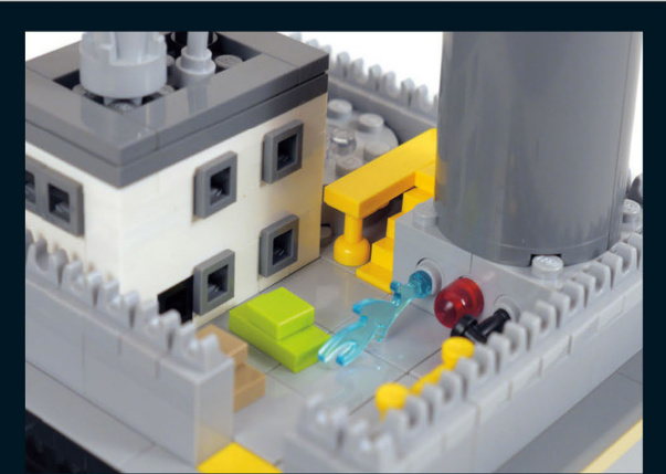
seaport
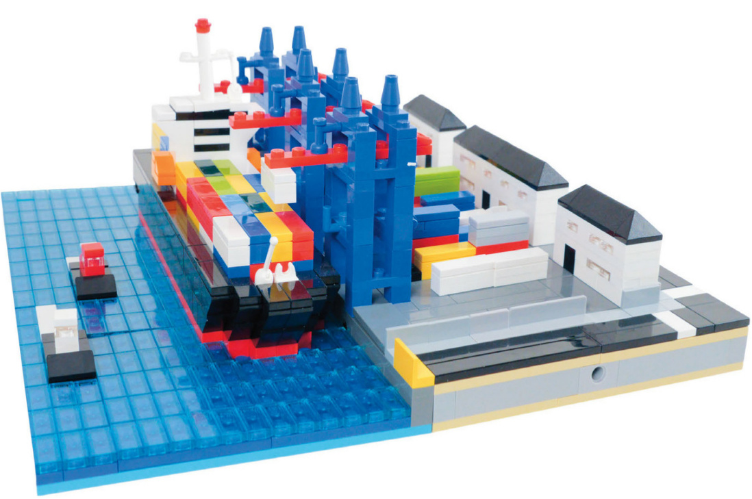
This seaport, container yard and ship really bring this city to life. The port is complete with loading cranes and tugboats as well.

Corner Condominiums
These corner condominiums havea Europeanstyle thatwould look great in any city layout.The gated courtyard in front provides a sharedfrontyard for theresidents.Both buildings feature full interiors,including kitchens,living areas,a bedroom,and even a LEGO toy building room. Let’s get started!
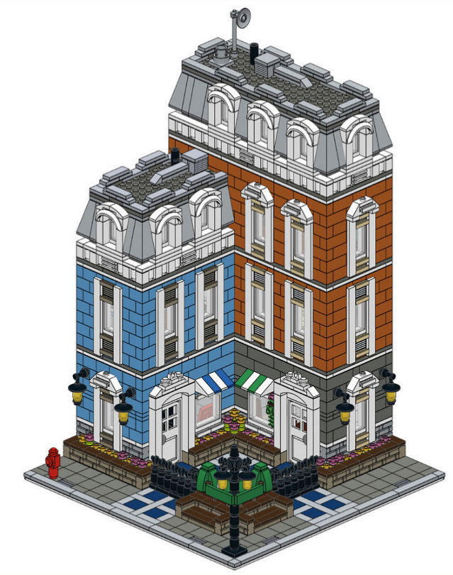
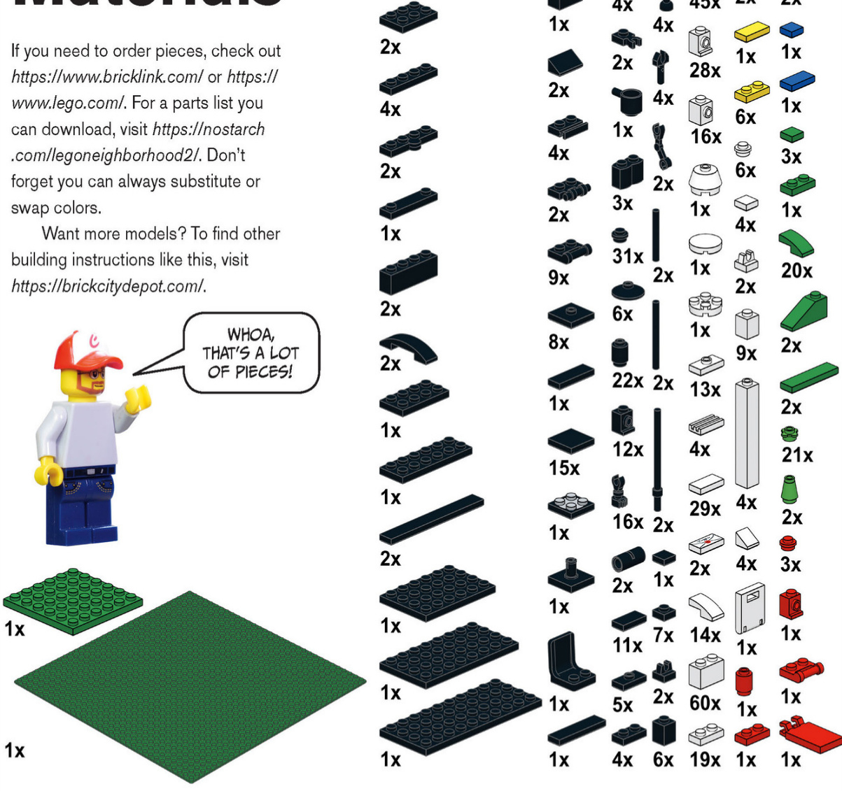
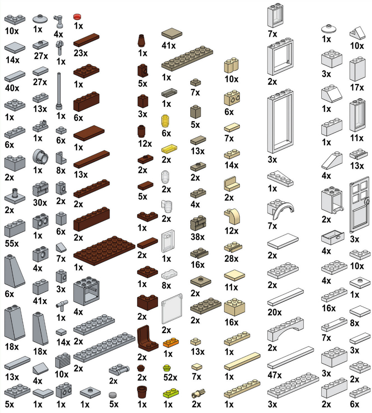
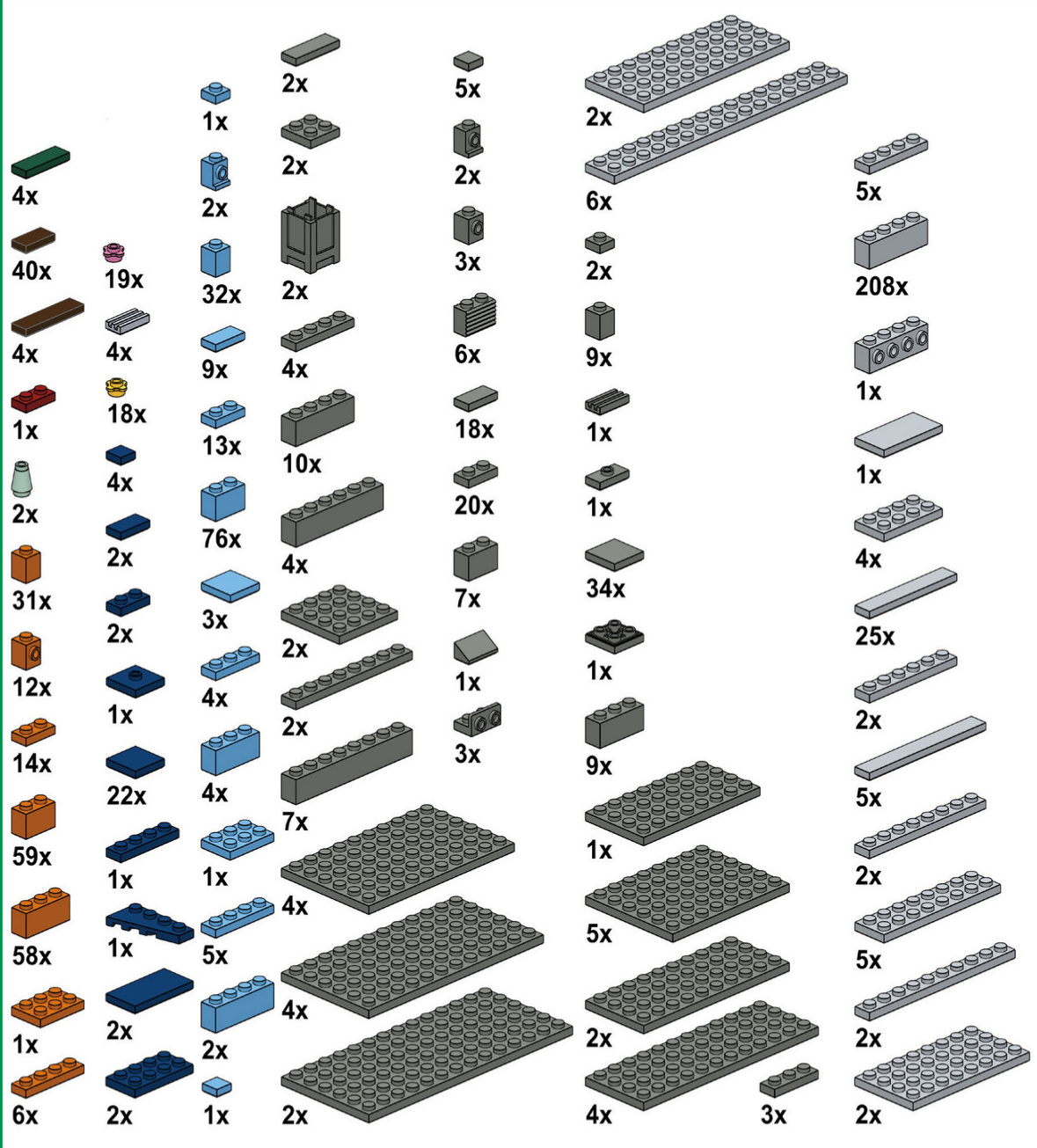
First Floor
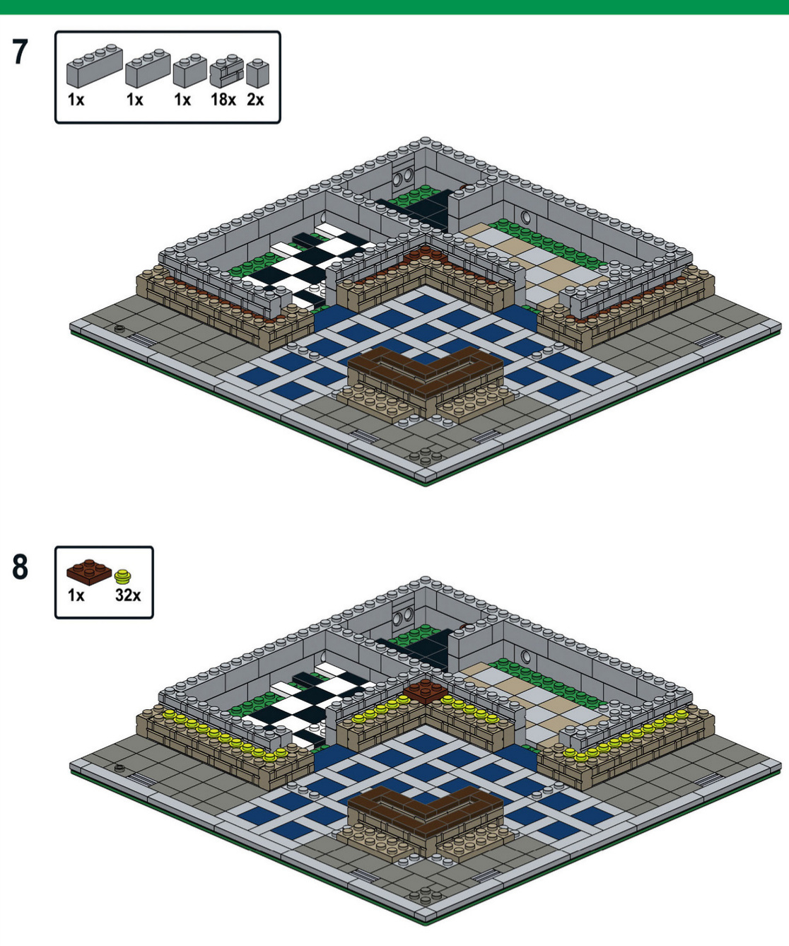
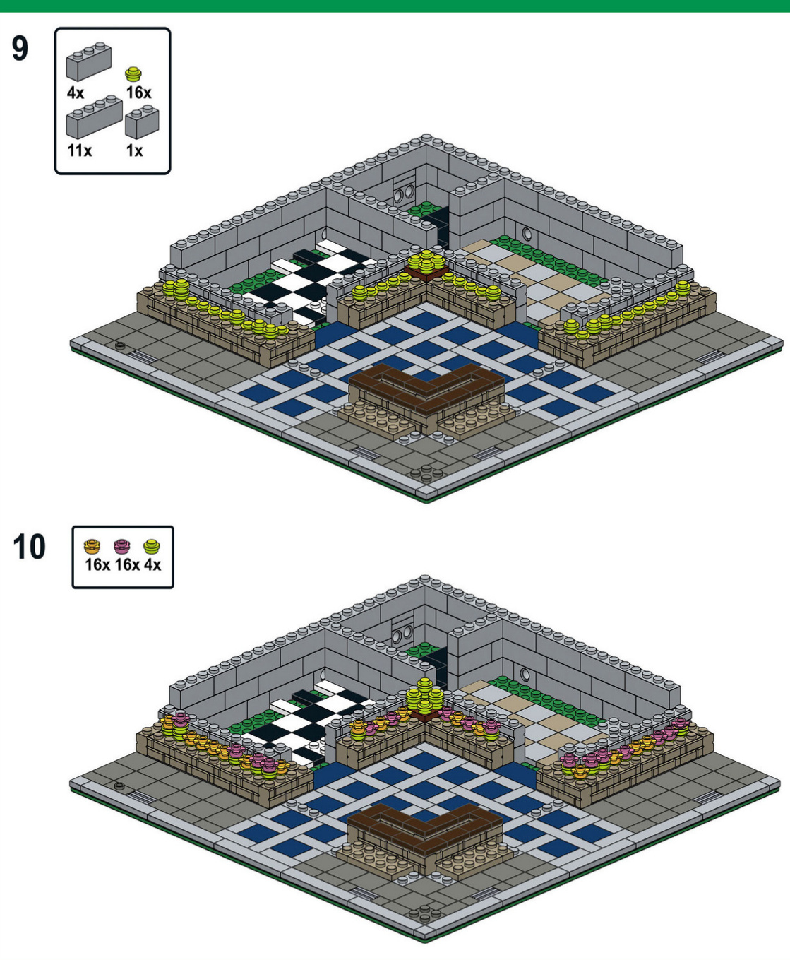
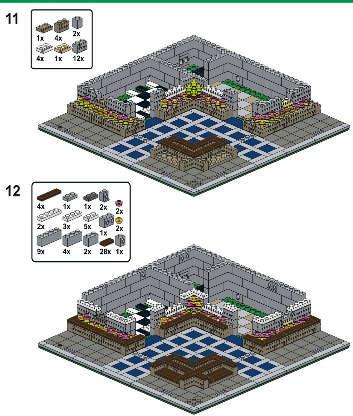
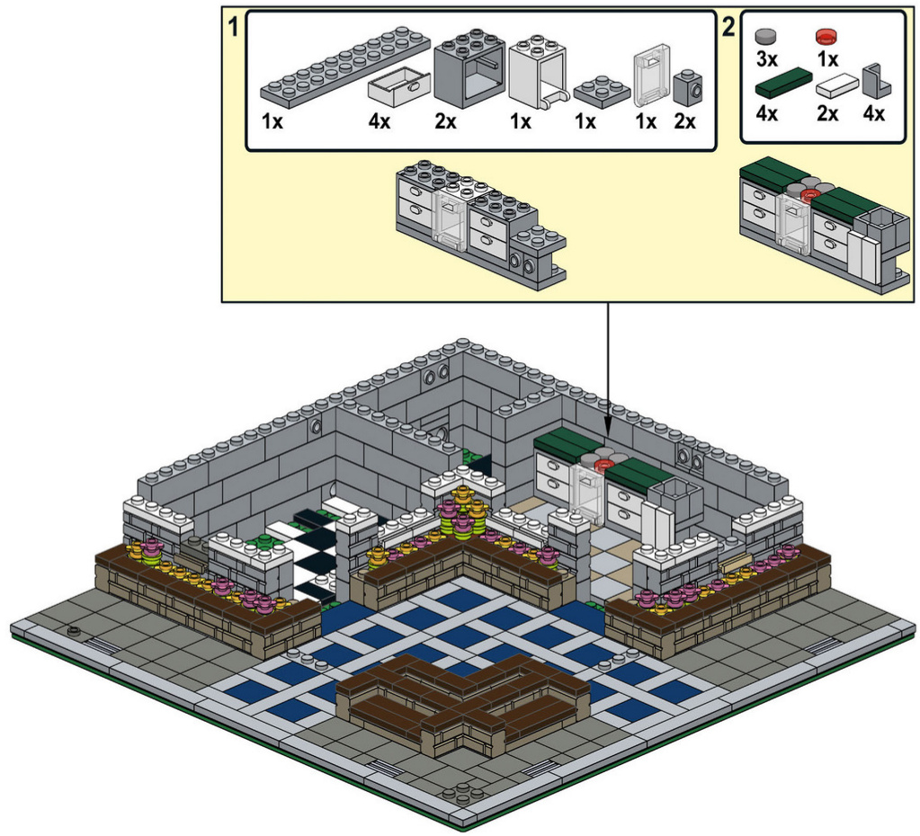
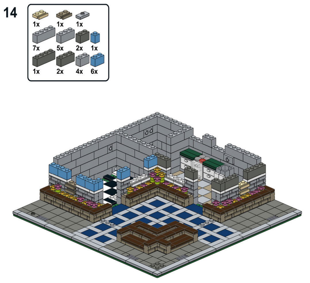
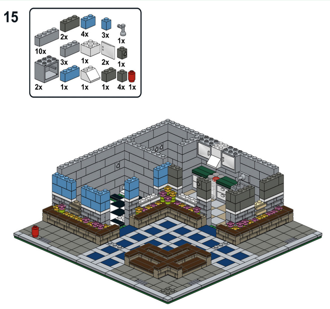
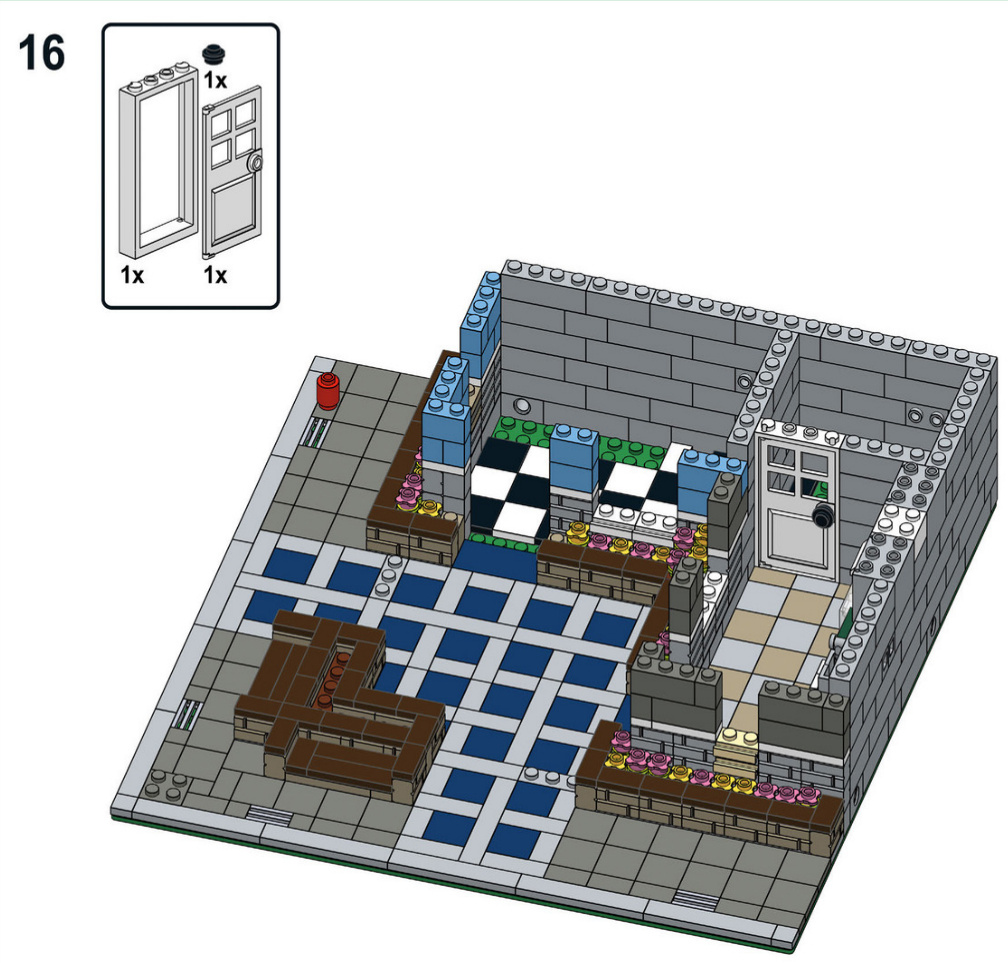
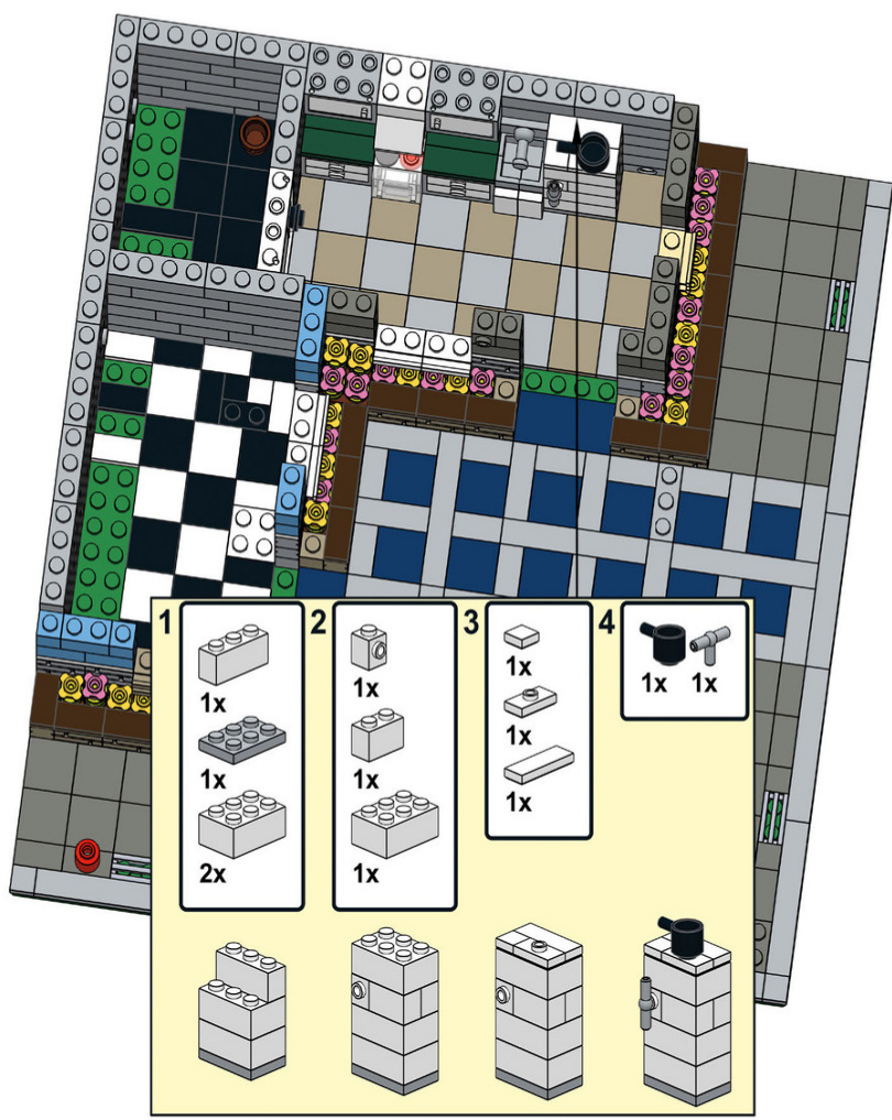
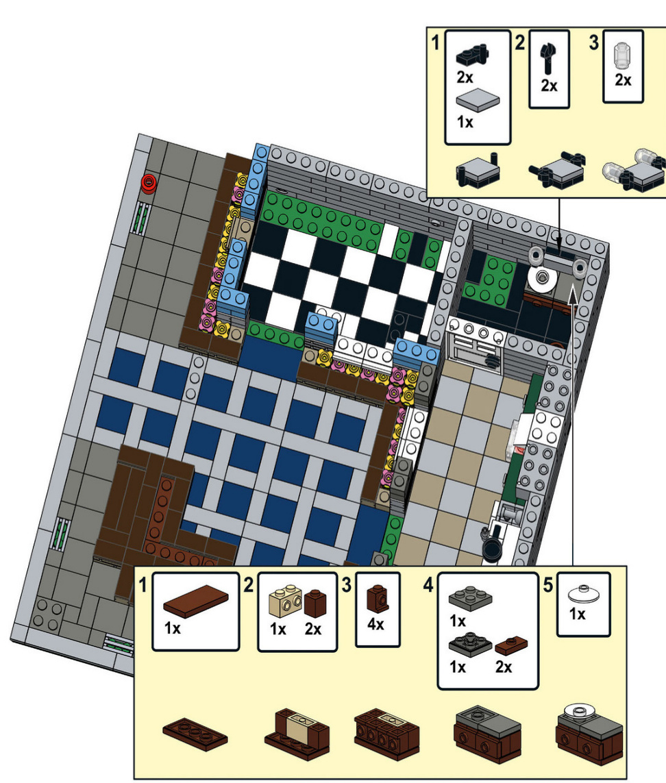
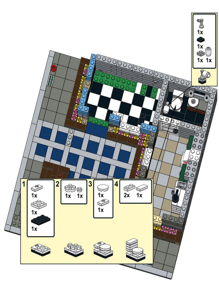
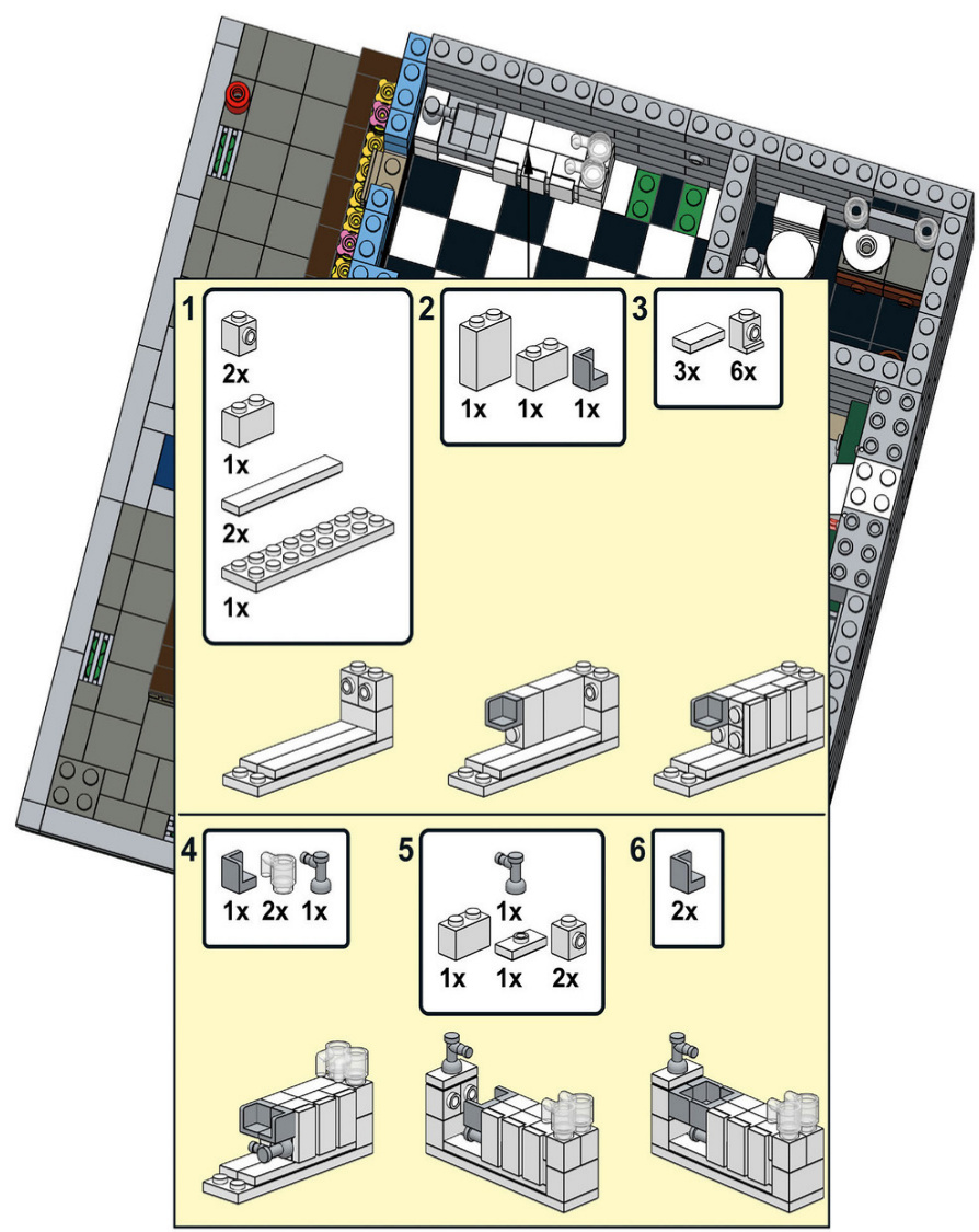
21
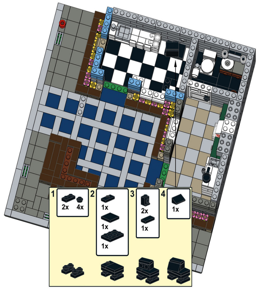
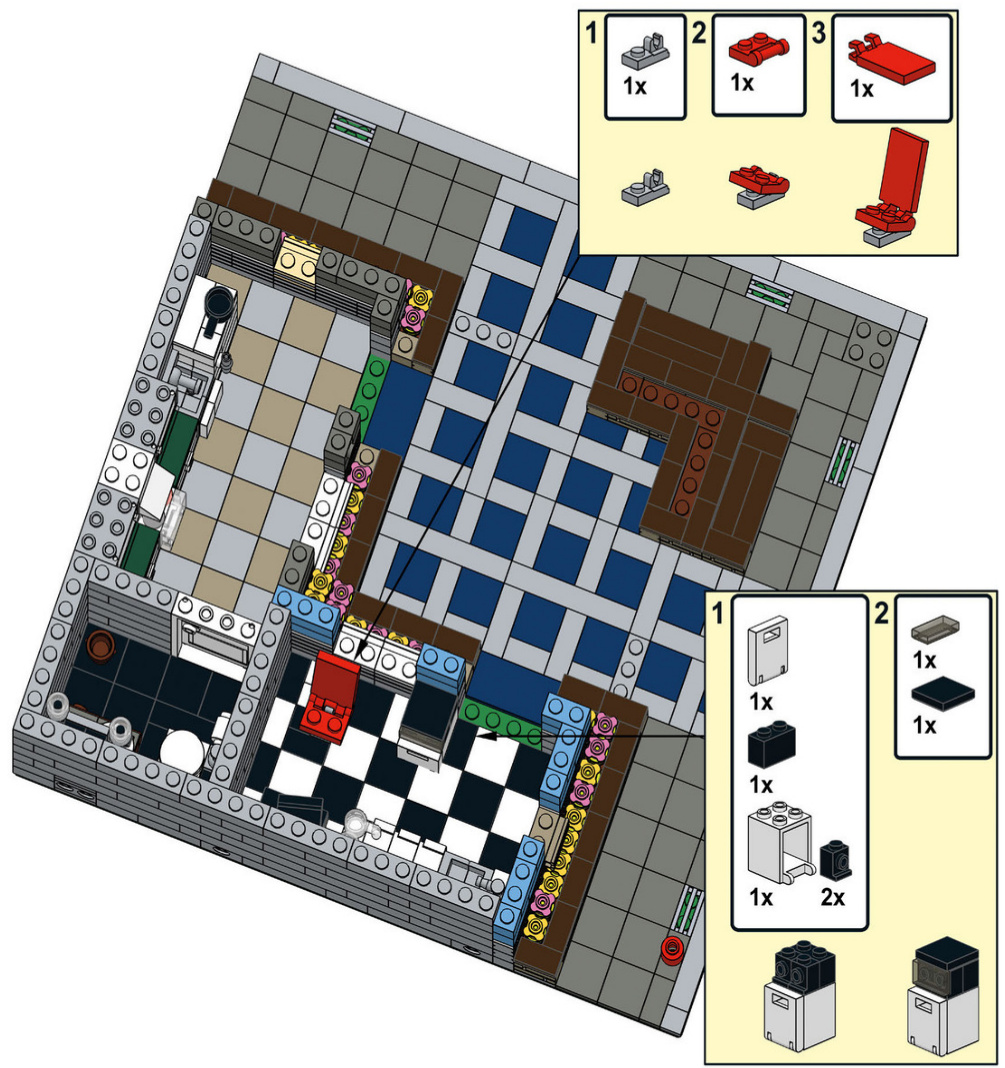
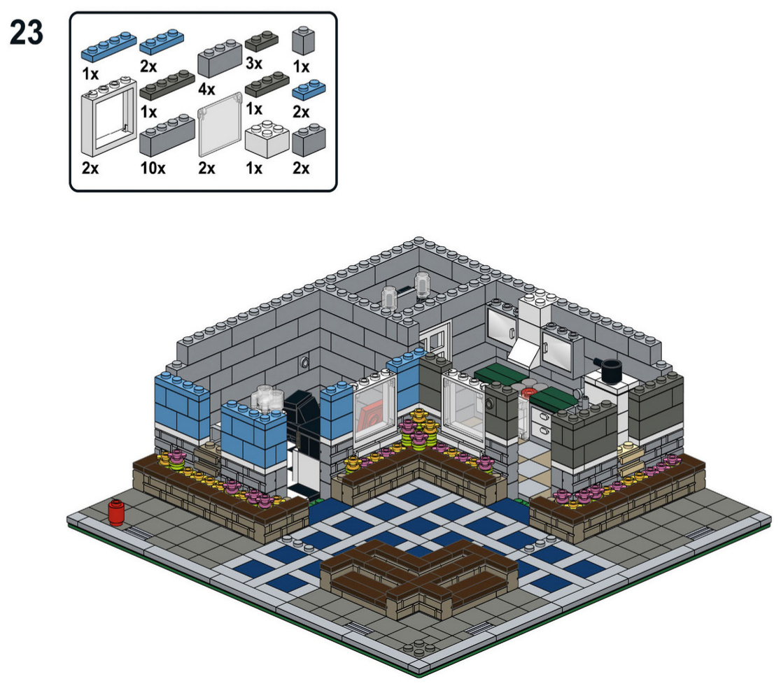
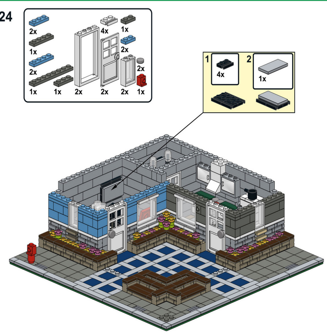
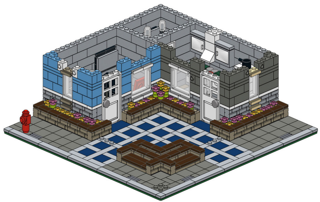
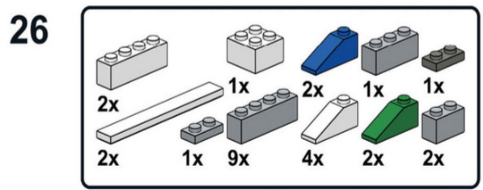
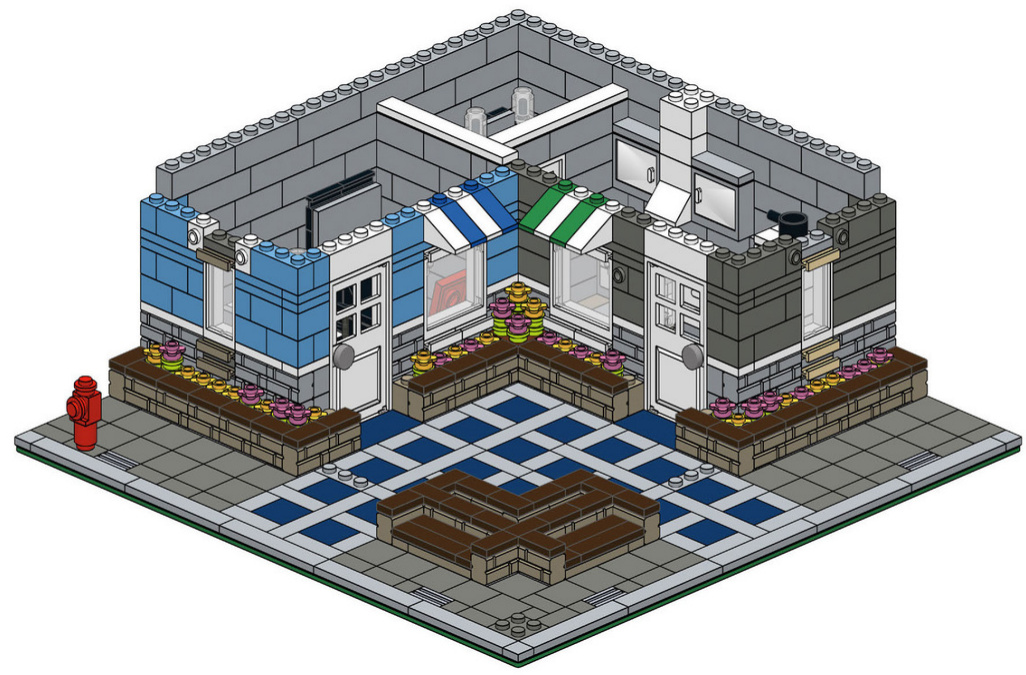
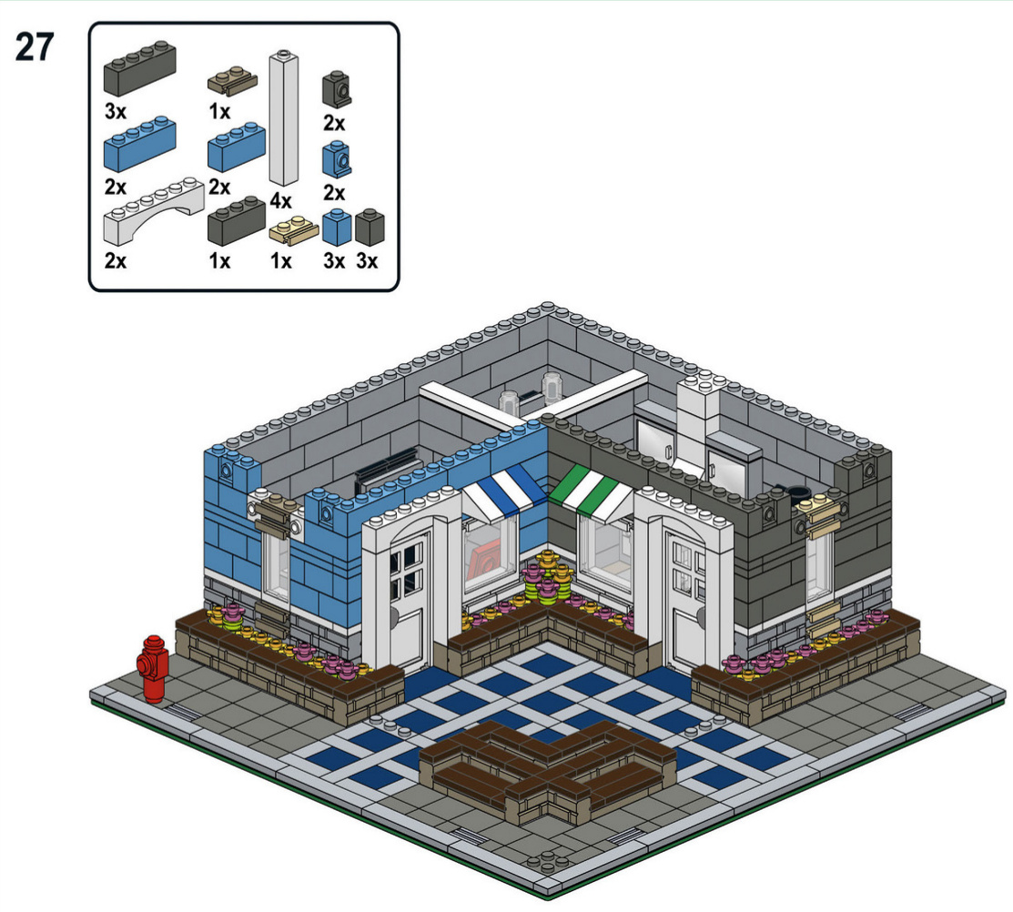
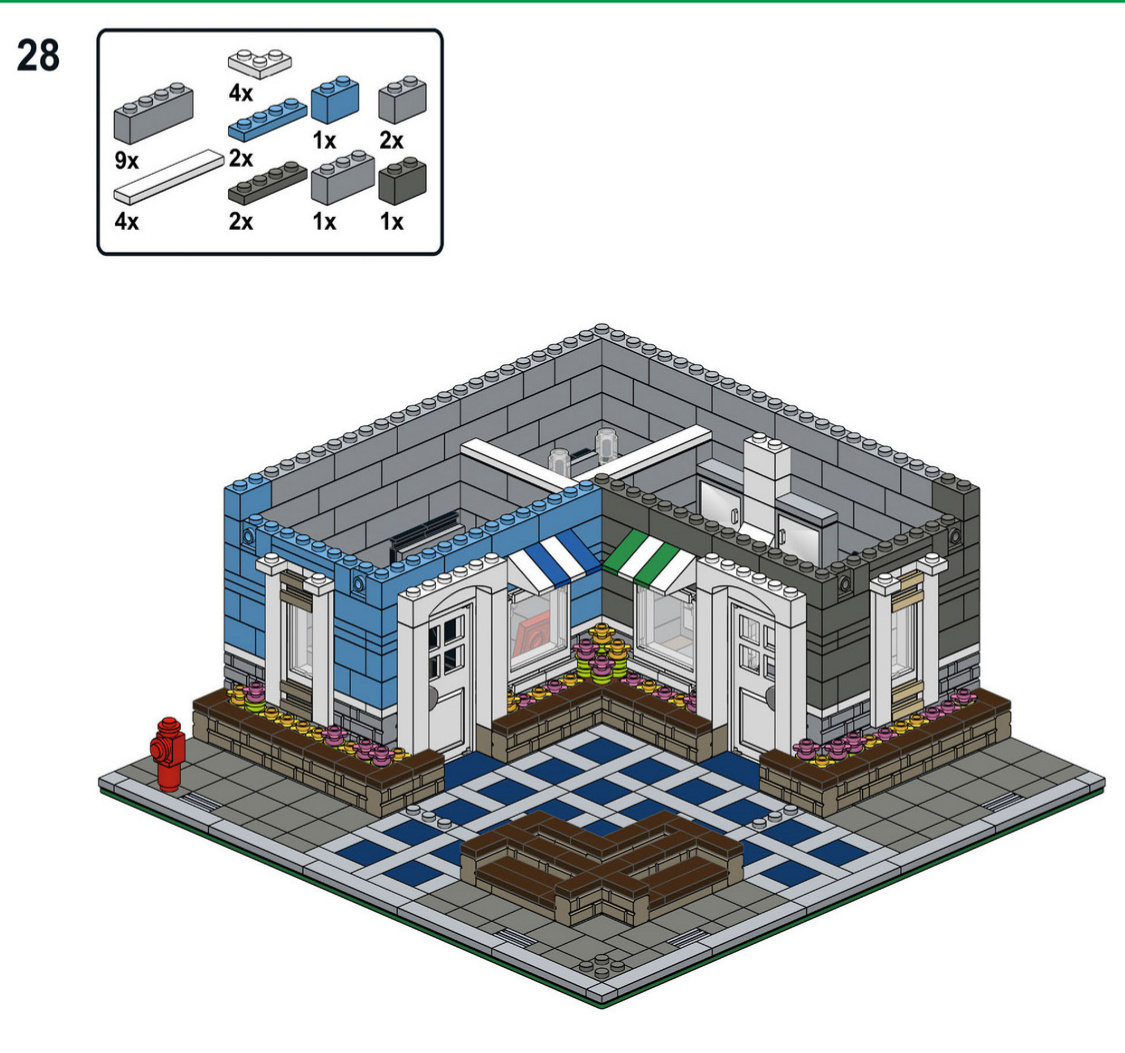
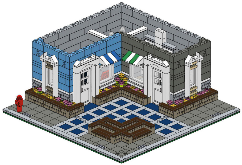
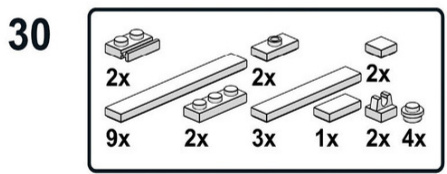
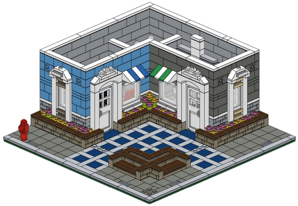
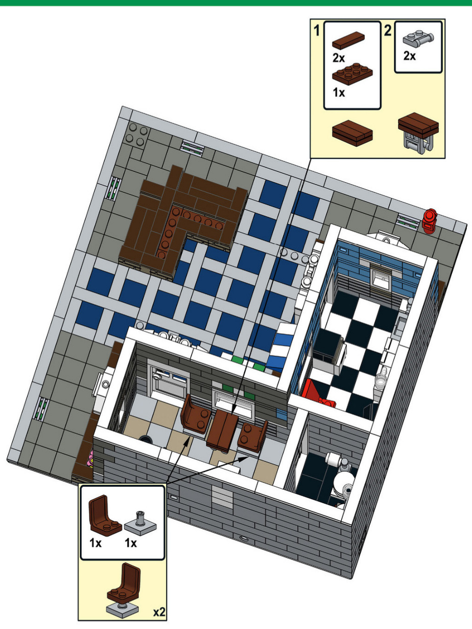
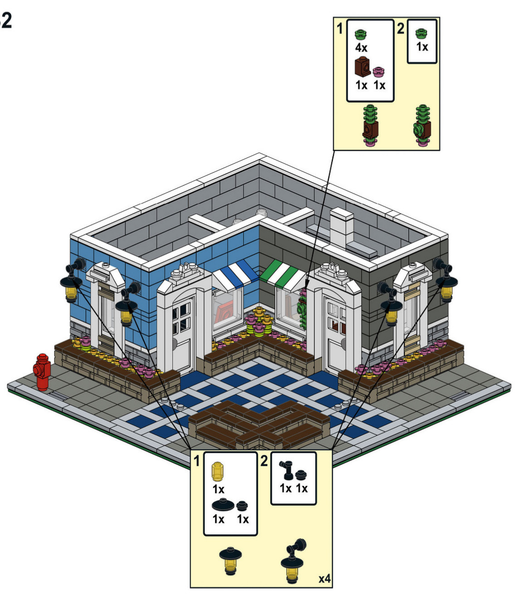
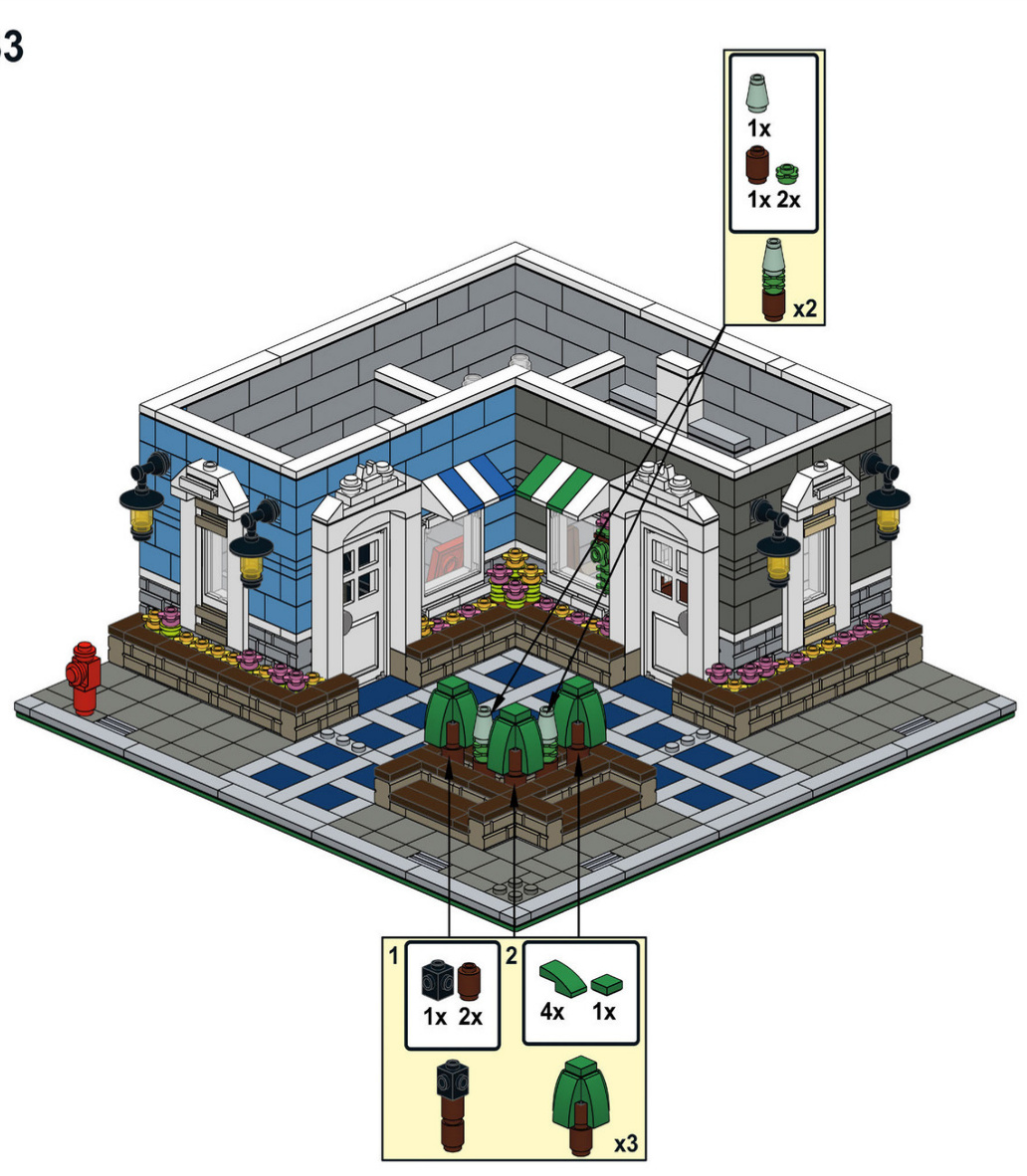
34
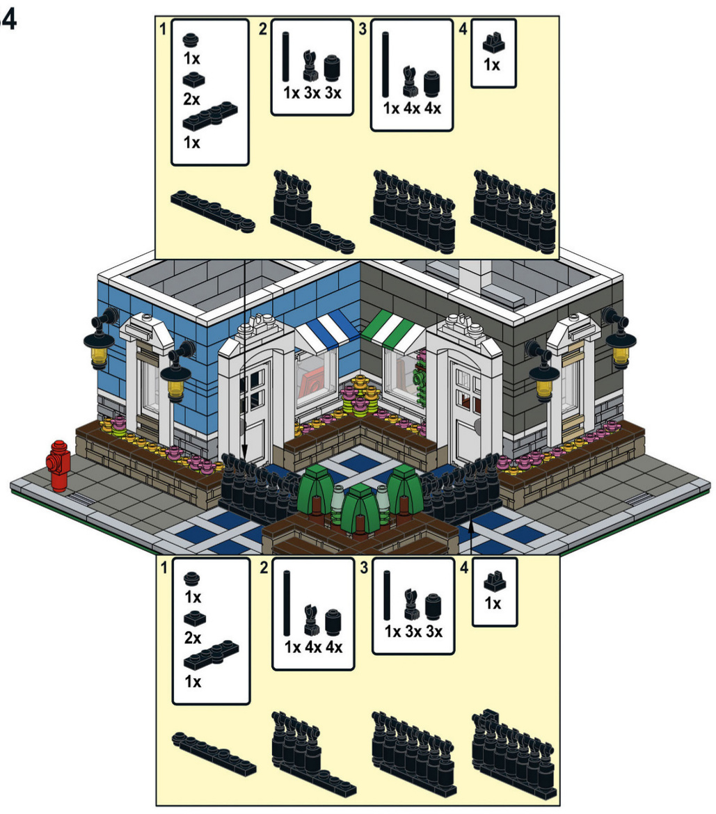
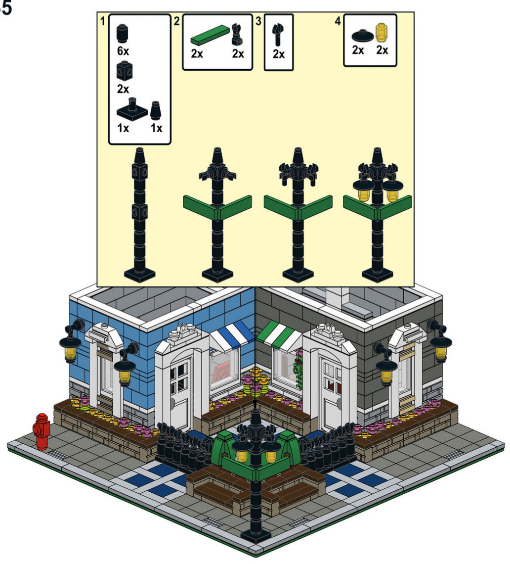
Second Floor
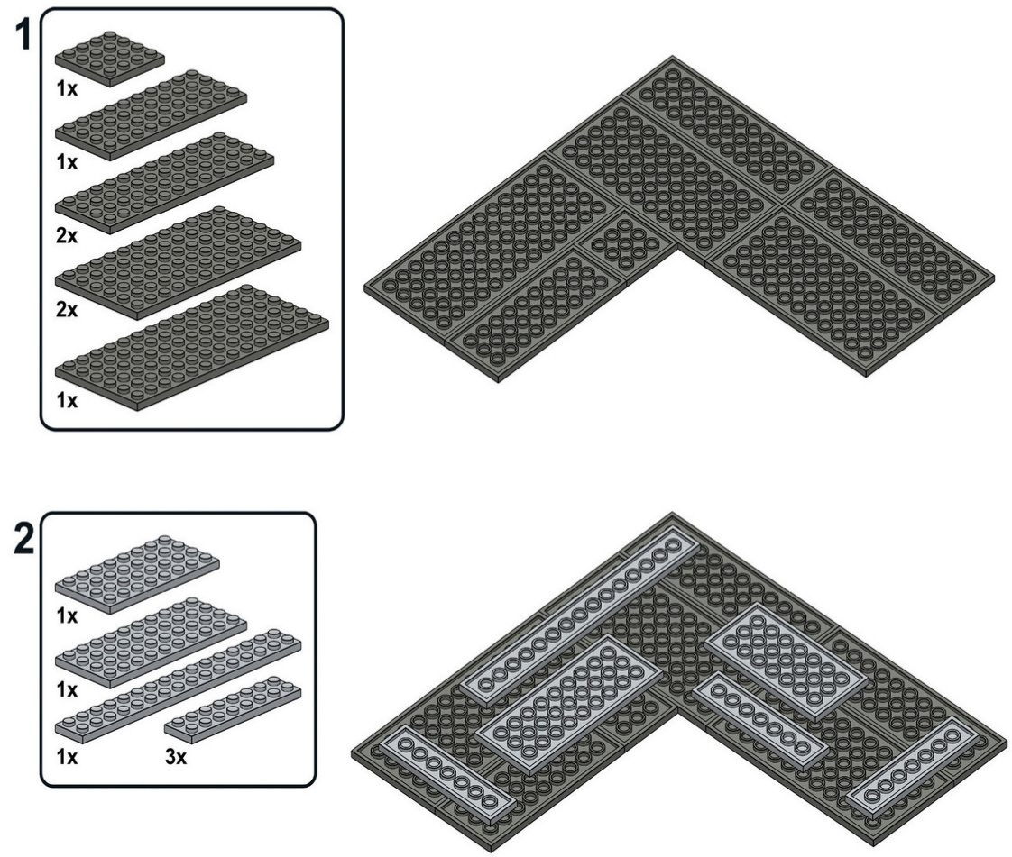
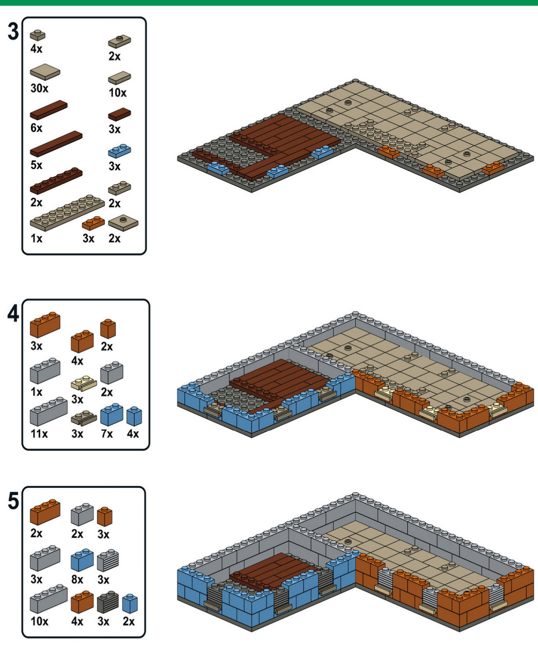
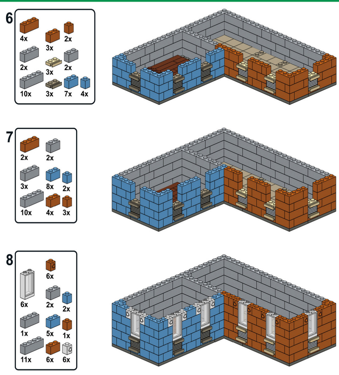
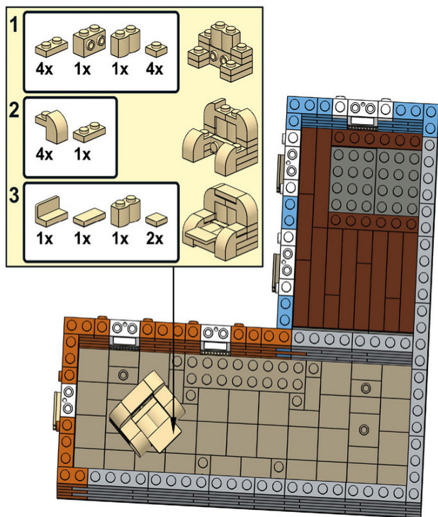
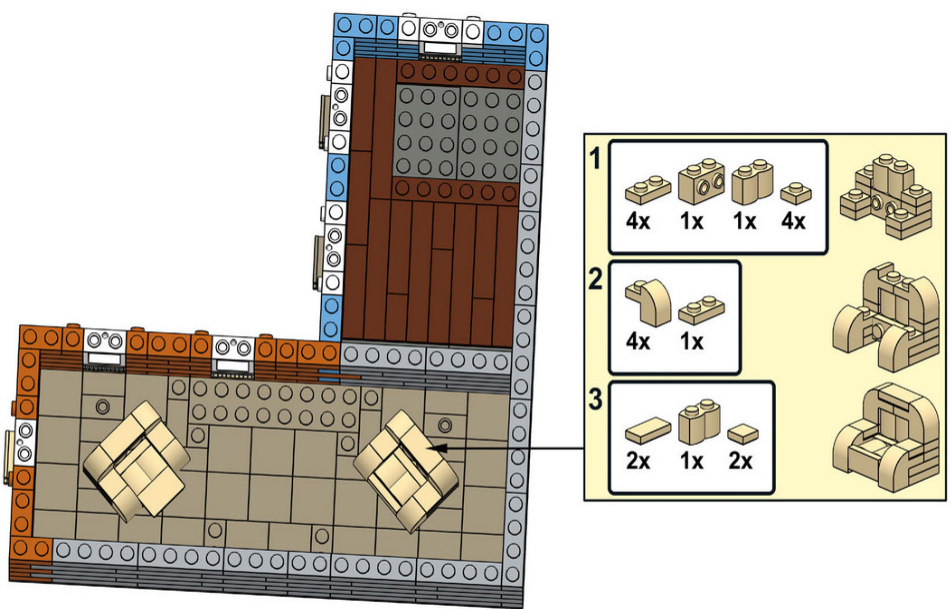
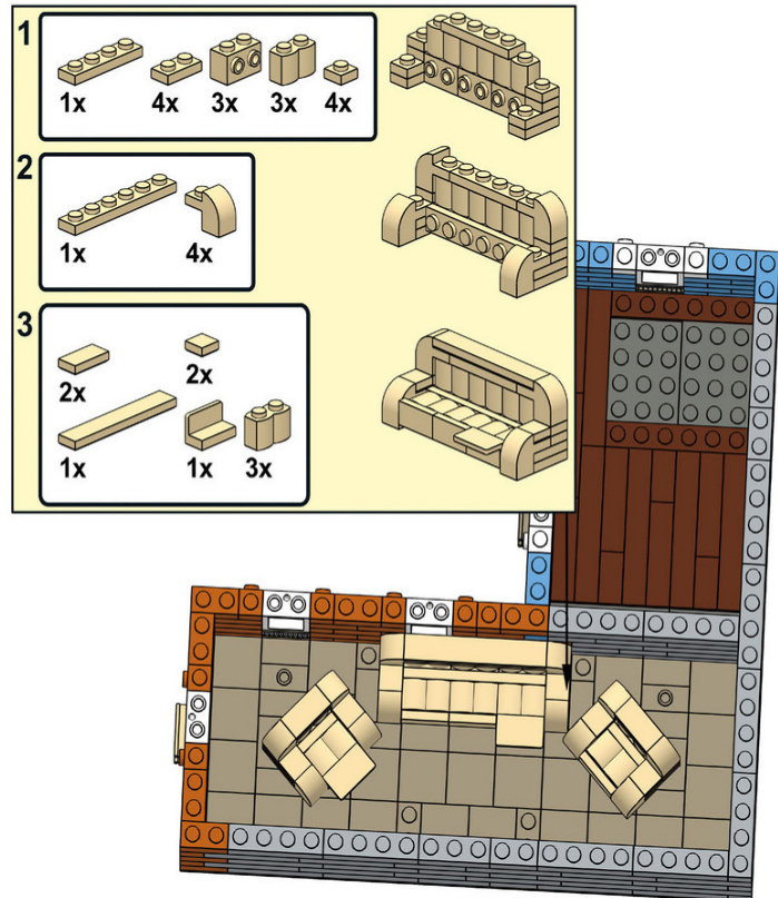
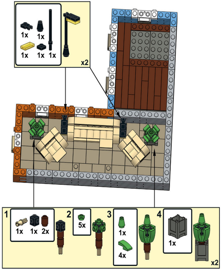
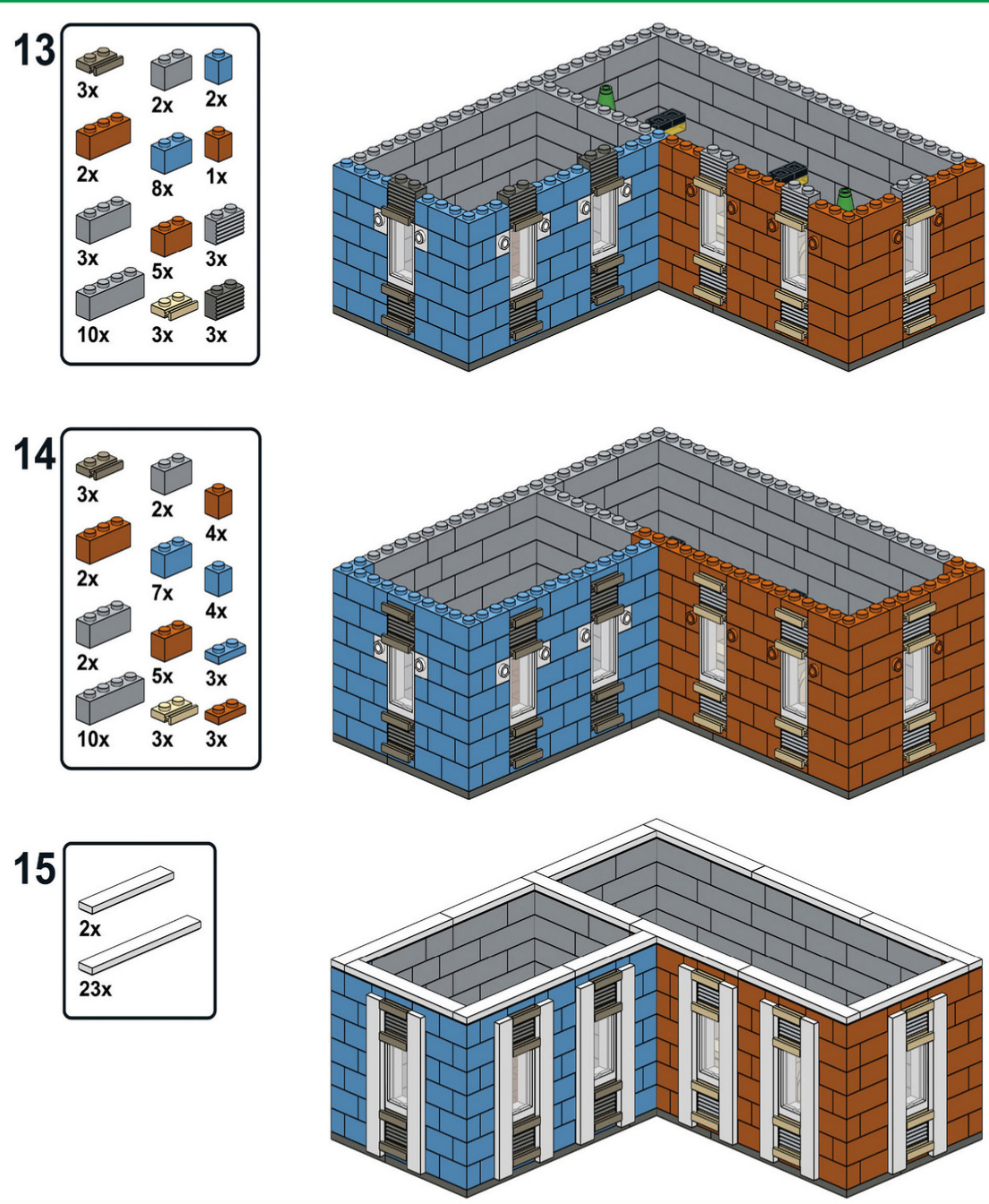
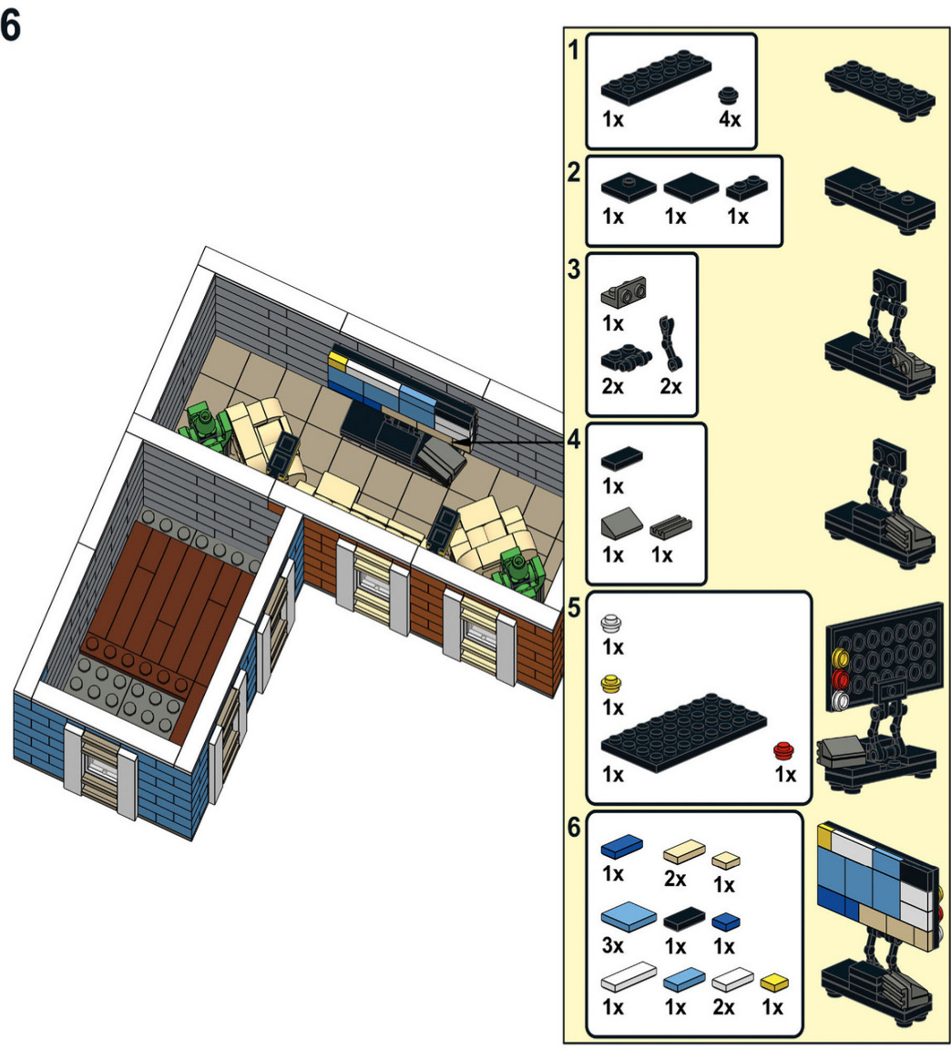
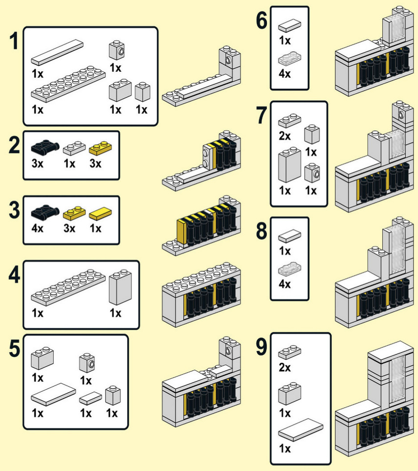
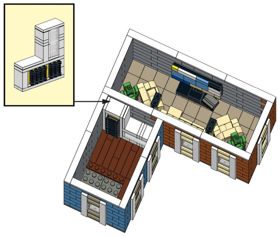
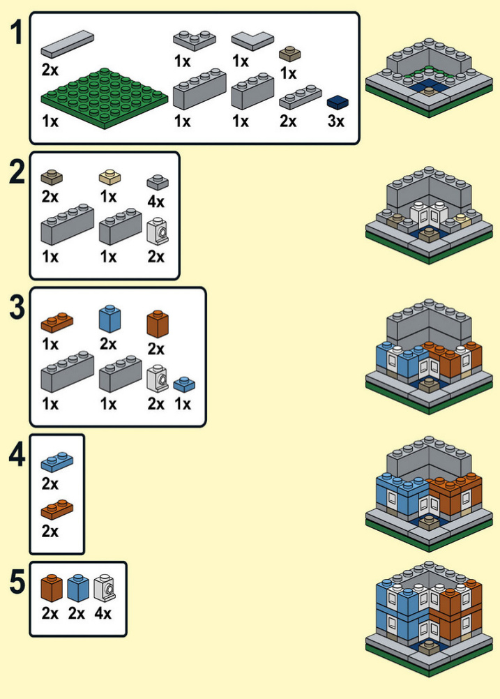
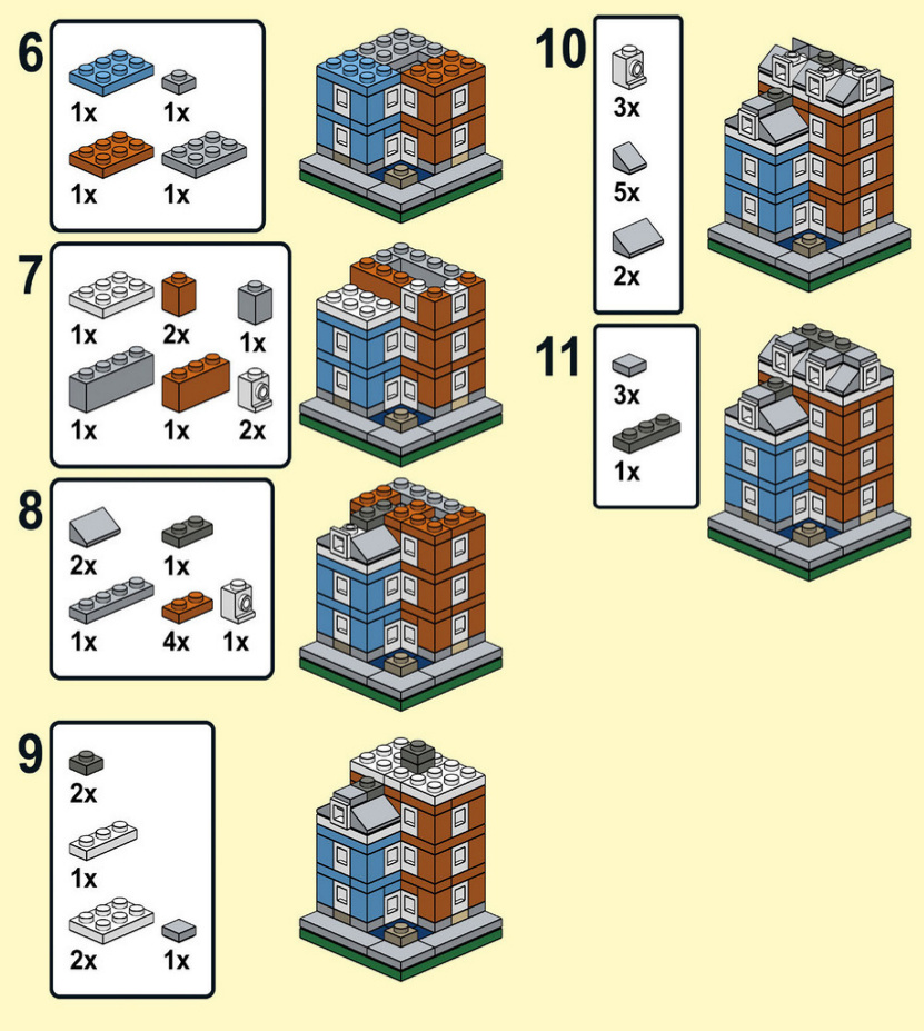
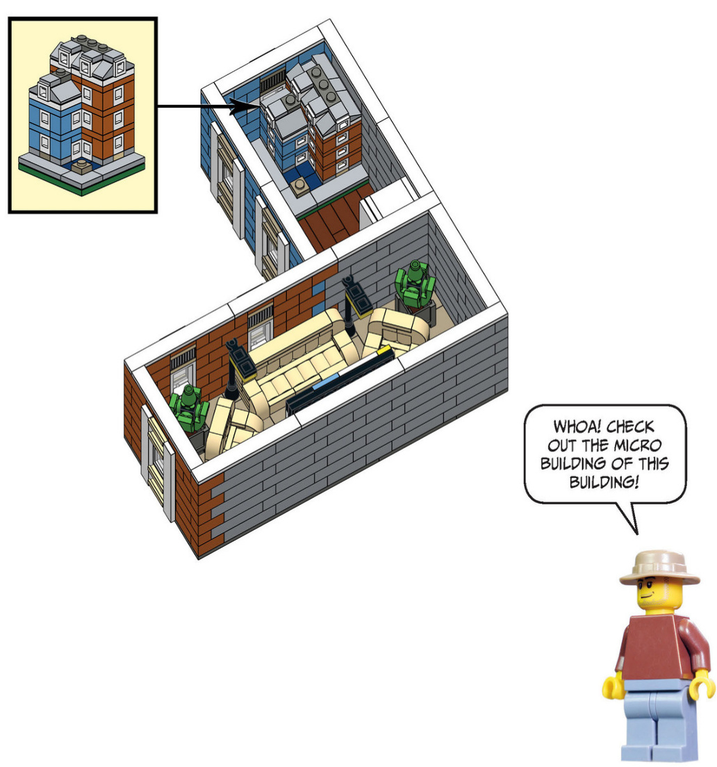
Third Floor
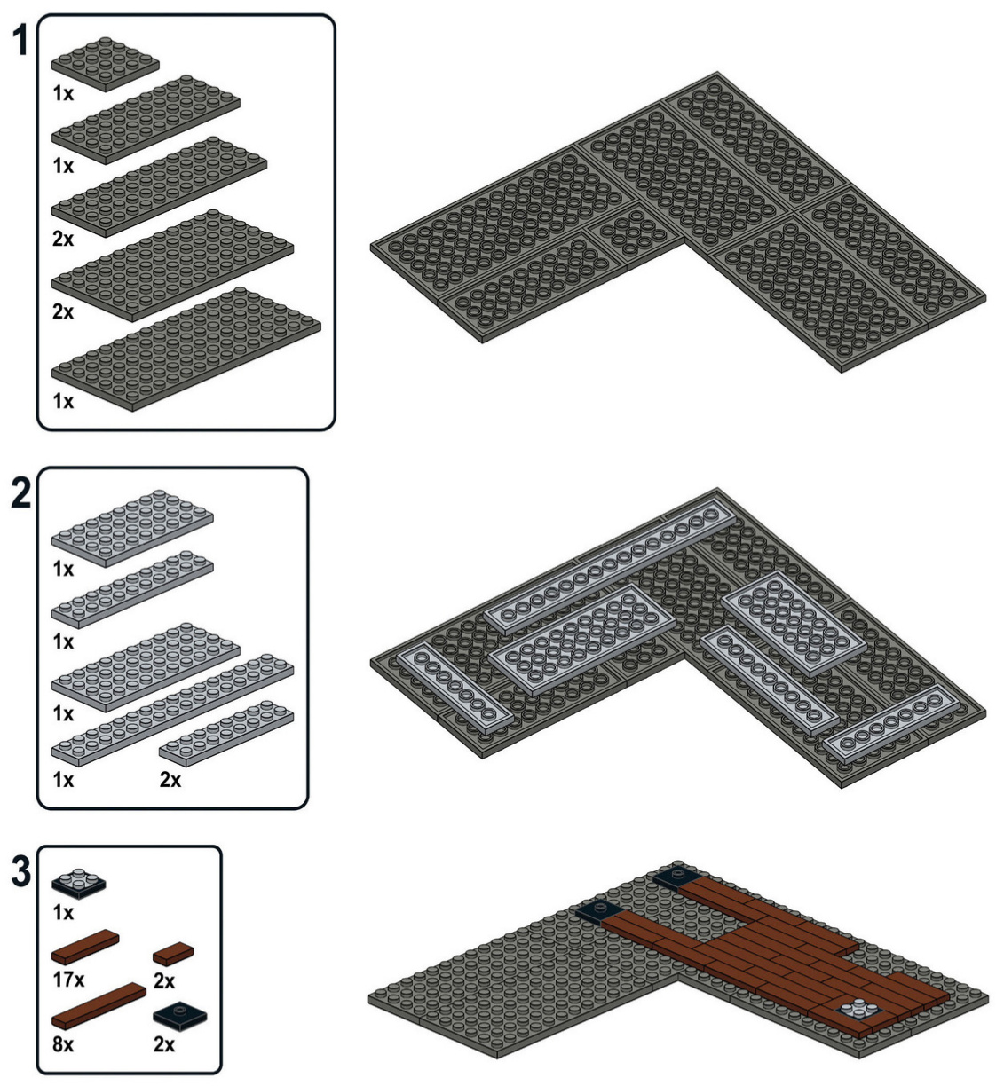

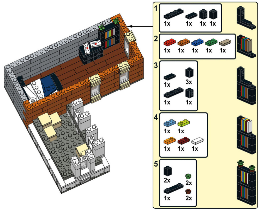
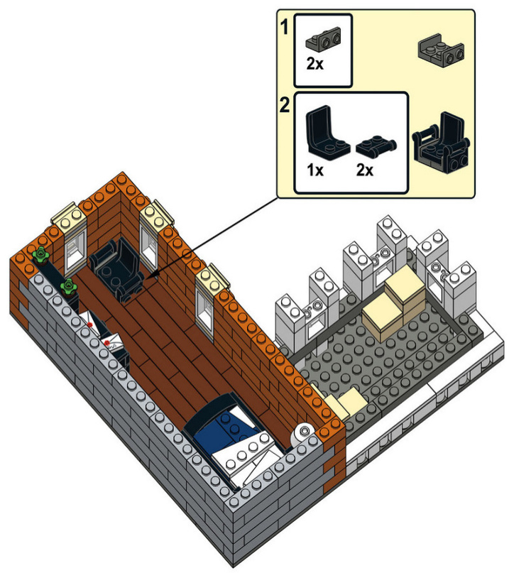
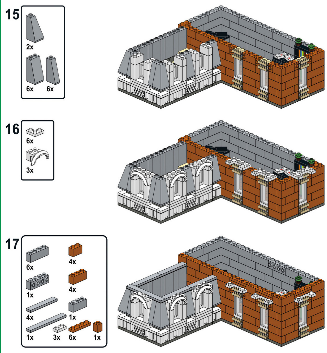
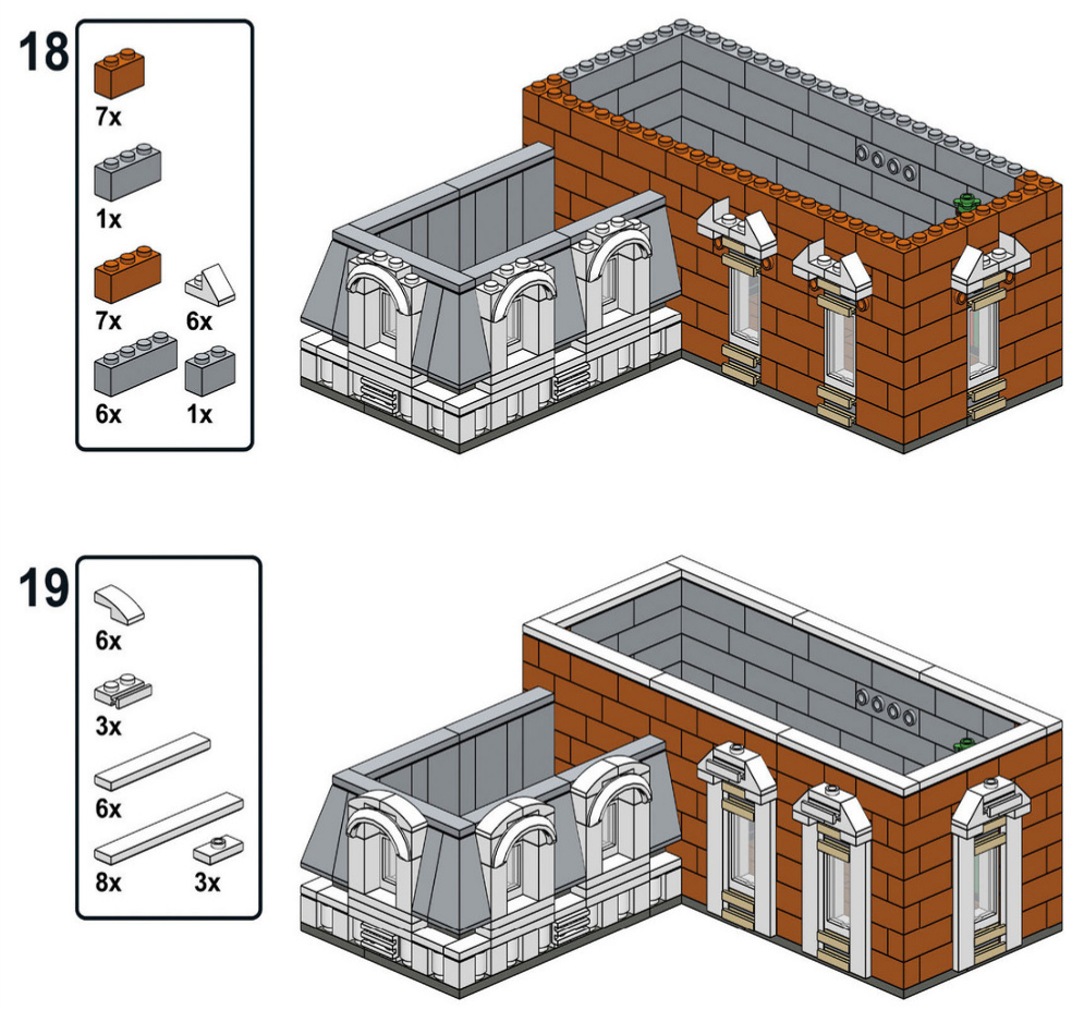
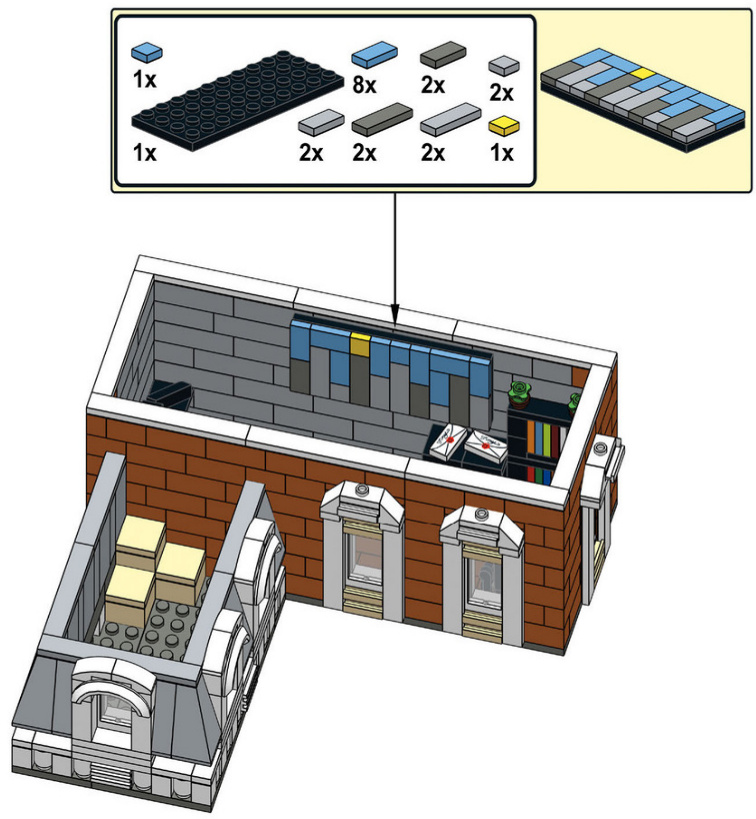
Attic
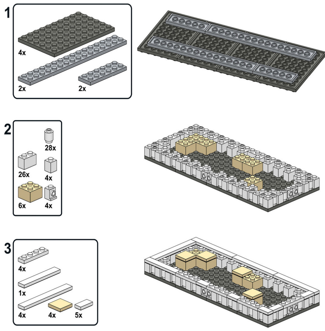
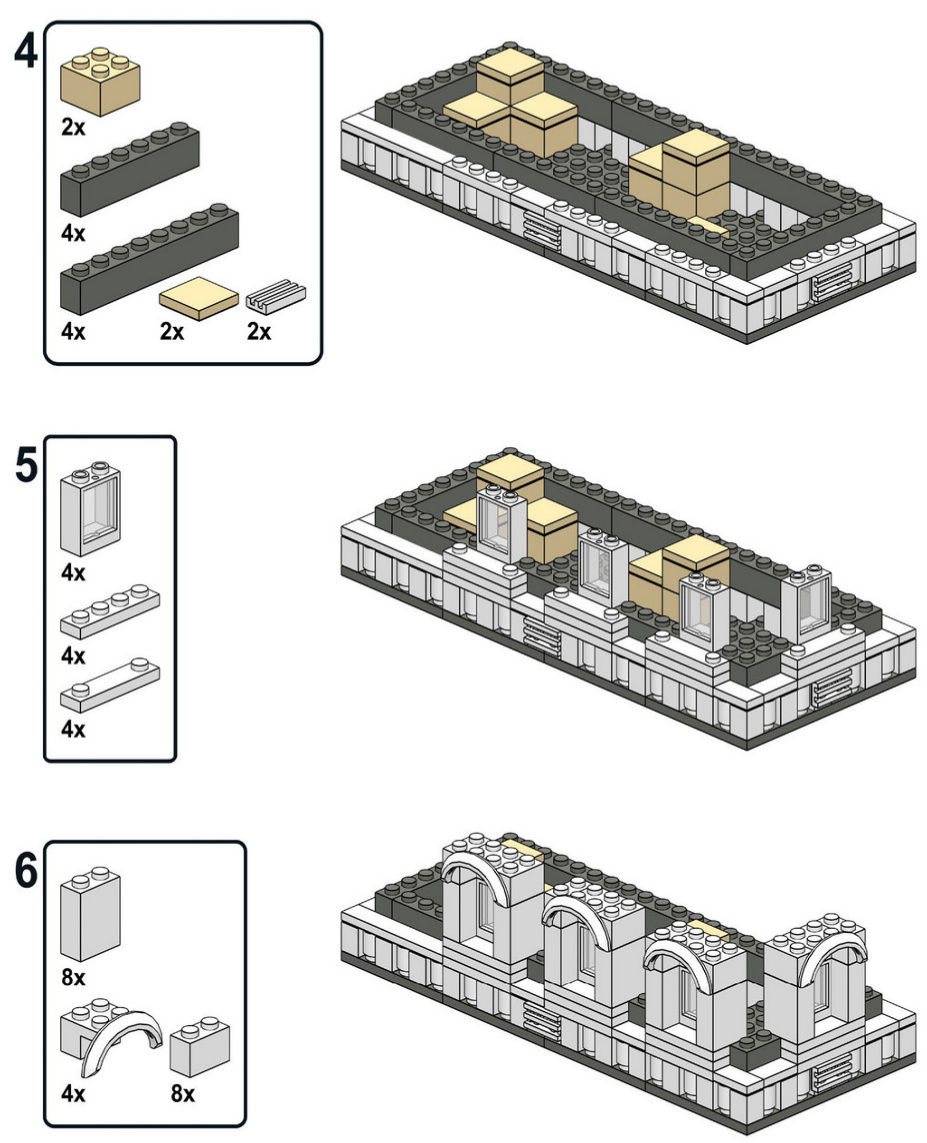
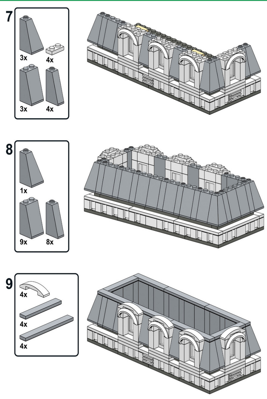
Orange Roof
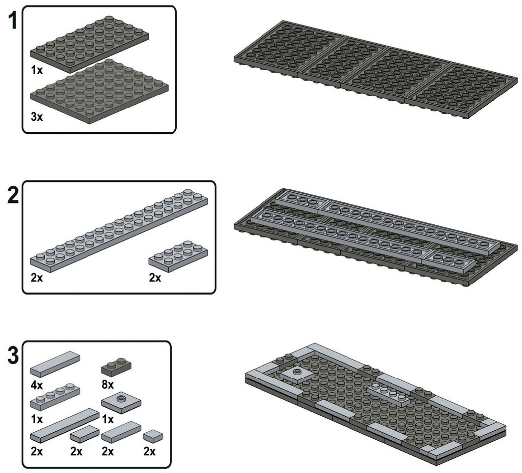
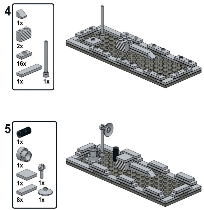
Blue Roof
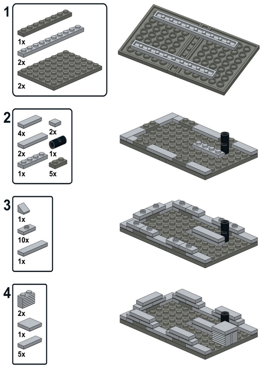
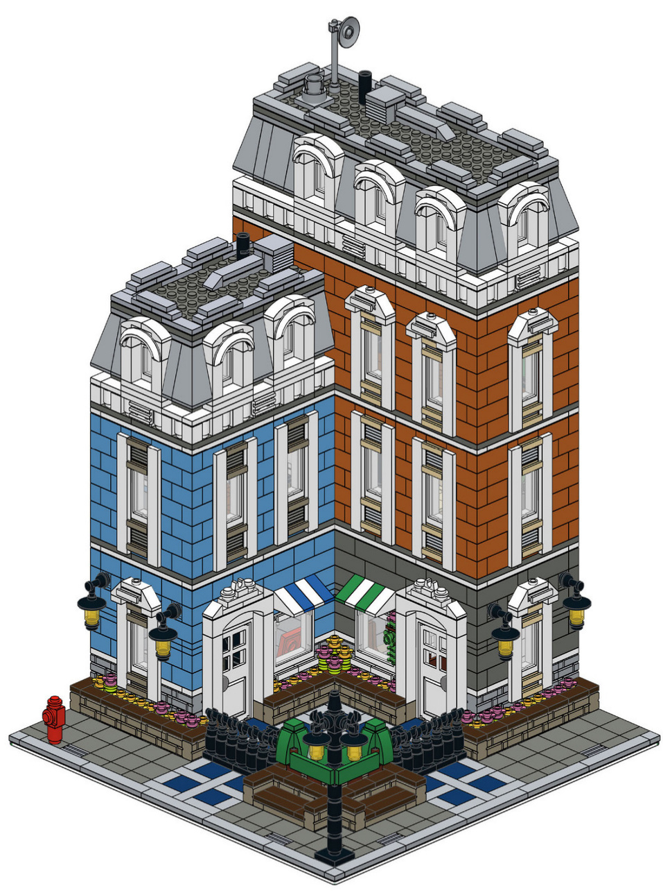
WEHOPETHAT OURTOUR THROUGHTHE CITY ANDTHE BUILDINGINSTRUCTIONSHAVE INSPIREDYOUTOMAKEA MODULARBUILDINGOFYOUR OWN-ORAMICROSCALE BUILDING!
FORMORE
INSPIRATION,PICK
UPTHELEGO
NEIGHBORHOOD
BOOK.
BUILDTHELEGO CITY OFYOURDREAMS!
In The LEGO Neighborhood Book 2, you’ll learn to create buildings with details like charming balconies, ornate roofs, and lush gardens. Try your hand at interior design and fill your buildings with furniture, houseplants, and other creative decorations. Put the finishing touches on your model with sidewalks, lampposts, mailboxes, and even an entire city park. Snap together a few houses, shops, and apartment buildings to create your own amazing LEGO neighborhood.
INSIDEYOU’LLFIND:
· Dozens of new ideas to use in your own models · Inspiration for your own microscale city ■ Mini builds for a piano, DVD rental machine, newsstand, and much more ■ Step-by-step instructions for two complete multistory buildings
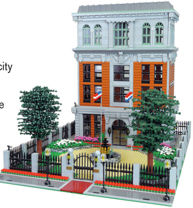
the lego Neighborhoodbook Build your own town! Brian Lyles and Jason Lyles
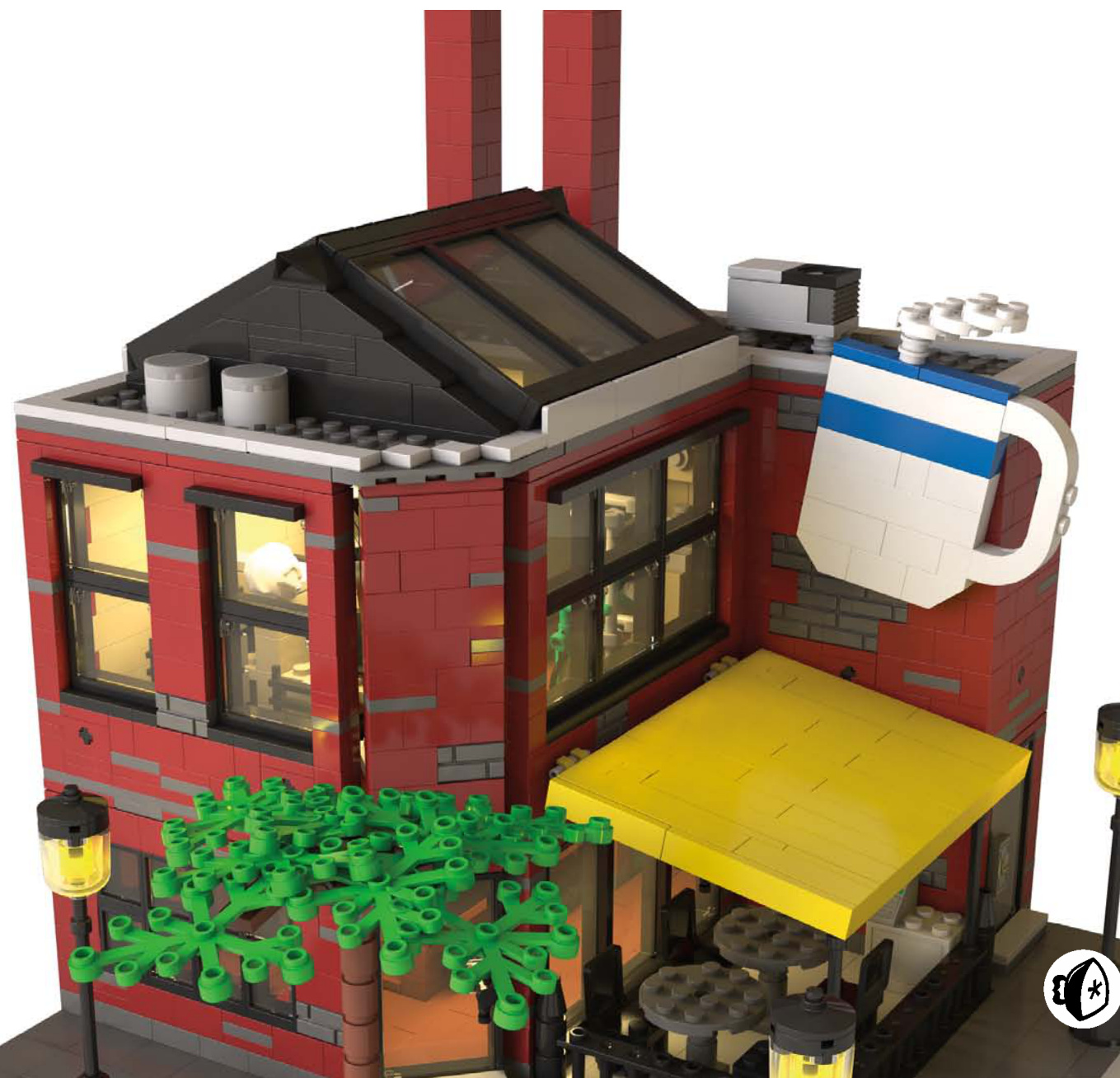
Getting Started 2 C with the Café Corner
Before you can make your own beautiful buildings, you’ll need
to understand the fundamentals. If you’ve ever built the LEGO Group’s official modular building kits, then you already know the basics of how LEGO buildings can be connected to form streets, neighborhoods, and cities. If you’re new to modular buildings, then you’ll want to pay special attention. You’ll need this knowledge to make sure that the buildings you create line up with official LEGO sets.
In October 2007, the LEGO Group released its first modular building, Café Corner (set #10182). This first building set the standard (sometimes called the Café Corner Standard) for how all later modular buildings would connect to one another and how the sidewalk would look. This style of building was developed by Jamie Berard, a designer at LEGO, and then embraced by a community of fans.
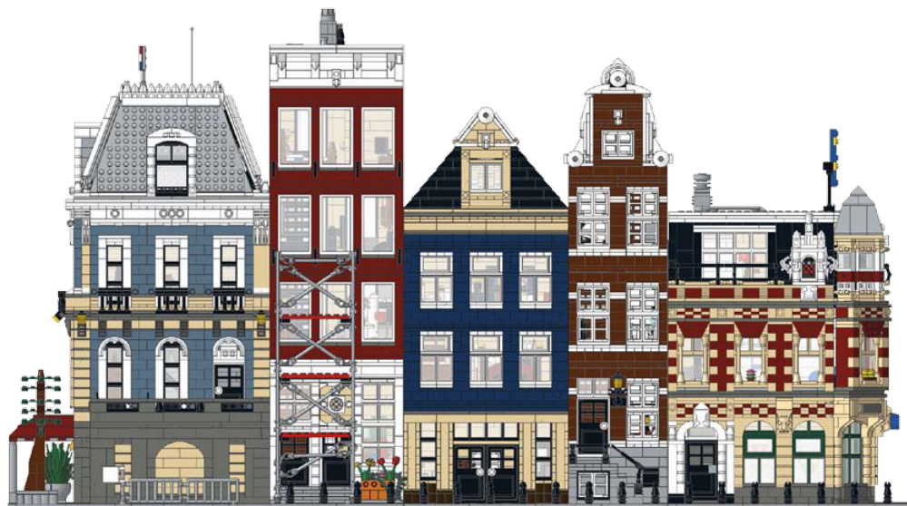
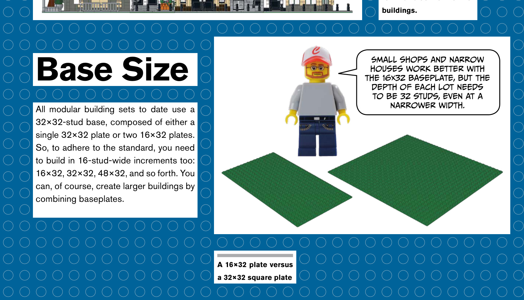
Connecting the Buildings
Buildings are connected to one another at the base via LEGO Technic pins. You’ll use four Technic bricks (part #3700) and two Technic pins (part #2780) for each connection.
Of course, you must space these Technic bricks consistently to match other buildings.
For a corner building, the placement of the Technic bricks remains the same: the 9-stud, 10-stud, 9-stud pattern shown at right.
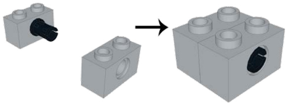
Technic pins hold your town together. They also allow you to build houses separately and connect them when you’re finished.
Even though you don’t have a building yet, you’ll want to place these Technic parts first for planning purposes.
Corner buildings maintain the same connections at the same spacing, just on a different side of the plate.
The Sidewalk
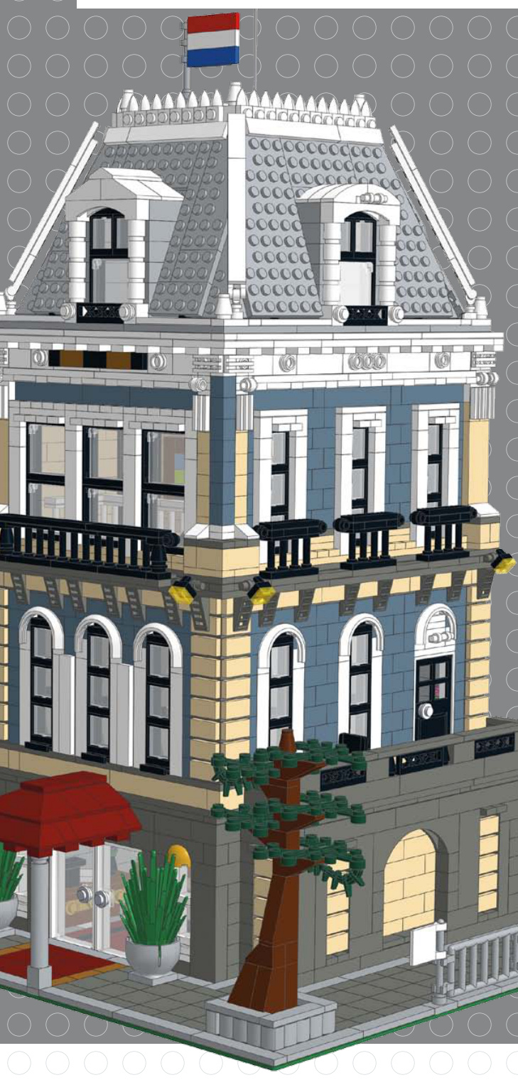
The sidewalk has a standard depth as well, but it has more options for versatility. Sidewalks may have stoops, staircases, flower boxes, or other details protruding from the building.
In the image below, you can see the first row of studs has light grey tiles covering it.
The second row of sidewalk studs is primarily made up of dark bluish-grey tiles. This second row of studs also has two tile grills that represent sewer grates, spaced six studs away from the outside edge of the plate.
The next four rows of studs are occupied by dark grey tiles running from left to right. The seventh row of the sidewalk is also made up of dark grey tiles.
The eighth and last row of the sidewalk is made up of light grey tiles.
A finished sidewalk
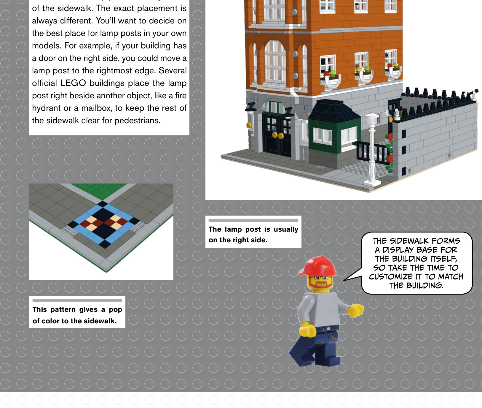
Building Creating Depth and Stackable Height Levels
With your sidewalk complete and your Technic bricks in place, you can get started with the building itself. While there’s an effective minimum of 15 studs for the depth of your building (the distance between the Technic bricks, plus a single row of studs in front), there are really no other rules. The depth of the building can vary from 15 to 24 studs, and some builders choose to make it very shallow from front to back to save pieces or to give their inhabitants a backyard. If you are creating a building with a large interior, you can build all the way to the back row of studs on the plate to allow for more space inside.
The height of the building and each floor is an aesthetic and practical decision. Most builders add at least one or two bricks above a doorframe before the next level starts. Some buildings have vaulted ceilings on the first floor or a big lobby, so the first floor would need to be much taller to accommodate the interior requirements. The building’s height is up to you, but remember that the sidewalls of taller buildings are visible when placed next to a shorter building. If you have a really tall building, consider adding windows (or other spots of visual interest) to the sides of the building to break up the flat, boring walls.
Why are they called modular buildings, anyway? It’s not just the buildings that can be connected. Each building has stackable levels that you can remove to see inside; they’re composed of modules that you can build separately from the whole. Around the top of the walls there is a layer of tiles so the next level can sit on the level below without grabbing any studs.
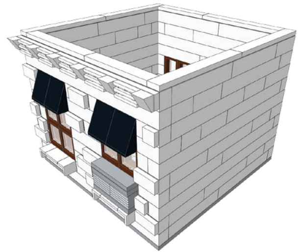
Tiles go around the top of the walls so the level above won’t connect to the one below.
There are several ways of locking the levels in place. One method is
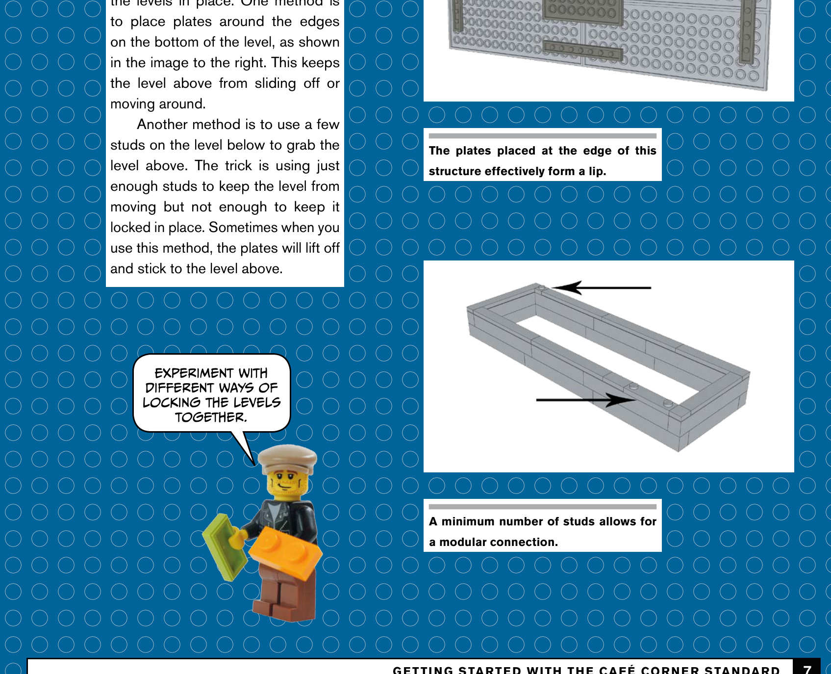
have to know the rules before you can know how to break them, right? Look around the city where you live, especially if there’s an older part of town. There’s no standard in real life; most of the cities we live in are charmingly chaotic. Buildings come in different shapes, sizes, widths, and architectural styles. Sometimes buildings have alleyways between them or large trees out front; some may be recessed from the road, while others are almost on top of it; some may be very skinny, while others are very wide; and some are two stories, or four stories, or more. Experiment!
The modular building theme is your inspiration, not an
exacting standard—
at least, that’s how we approach it.
Buying Bricks
you don’t already know about BrickLink, put own this book and go to http://bricklink.com/ ght now. BrickLink is a huge aftermarket website here thousands of sellers from all over the orld sell millions of individual LEGO pieces just about every part and color combination er made.
The Design
The first step of any build is deciding what type of building to make. You should have a good idea of what you are going to build—whether it’s a police station, a house, or a restaurant—before you actually start. Once you’ve decided, you have two options: you can either build something entirely from memory, or you can find real inspiration. Just like artists sketching or painting, you’ll likely find reference material invaluable.
If you’re at a total loss about what to build, a good way to get started is to visit areas that feature buildings you like. You’ll start to notice architectural details and design. Take pictures of complete buildings or parts that you want to add to your own design.
And if you want to build something inspired from another country, just hop online. Search the Web for images, use Google Street View, fly over cities using Google Earth, or treat yourself to a 3D bird’s-eye view using Bing Maps. You can “drive” down almost any street in the world today, for free. You can also search for specific buildings (like a fire station, museum, or city hall) or even a certain architectural style.
Choosing Colors
Houses and businesses come in all shapes and colors. Adding vibrant colors to your houses can look great and bring some life into your city, but you might also want to throw in some more realistically colored houses, using dark red for brick houses, as well as white, tan, and some darker colors. Dark blue, dark green, dark orange, and dark tan all give a house some color without being over the top. The muted “sand” colors such as sand blue and sand green look great, too. On the right are some examples of modular buildings in these colors.
Using primary colors such as red and blue might not be your first pick, but when done properly, as in the Notting Hill–inspired houses on the next page, these colors can look great.
One key factor in determining the color for the house or building is the parts you have available to you. It’s a good idea to check the color guide in the BrickLink catalog (http://www .bricklink.com/catalog.asp) to see which pieces are made in the color you want to use. Certain plate and brick lengths aren’t made in every color, so this can restrict how you build certain parts of the model.
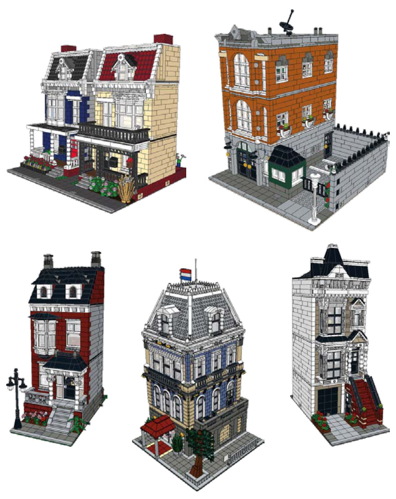
Clockwise from top left: dark blue and tan, dark orange, dark tan, sand blue, and dark red
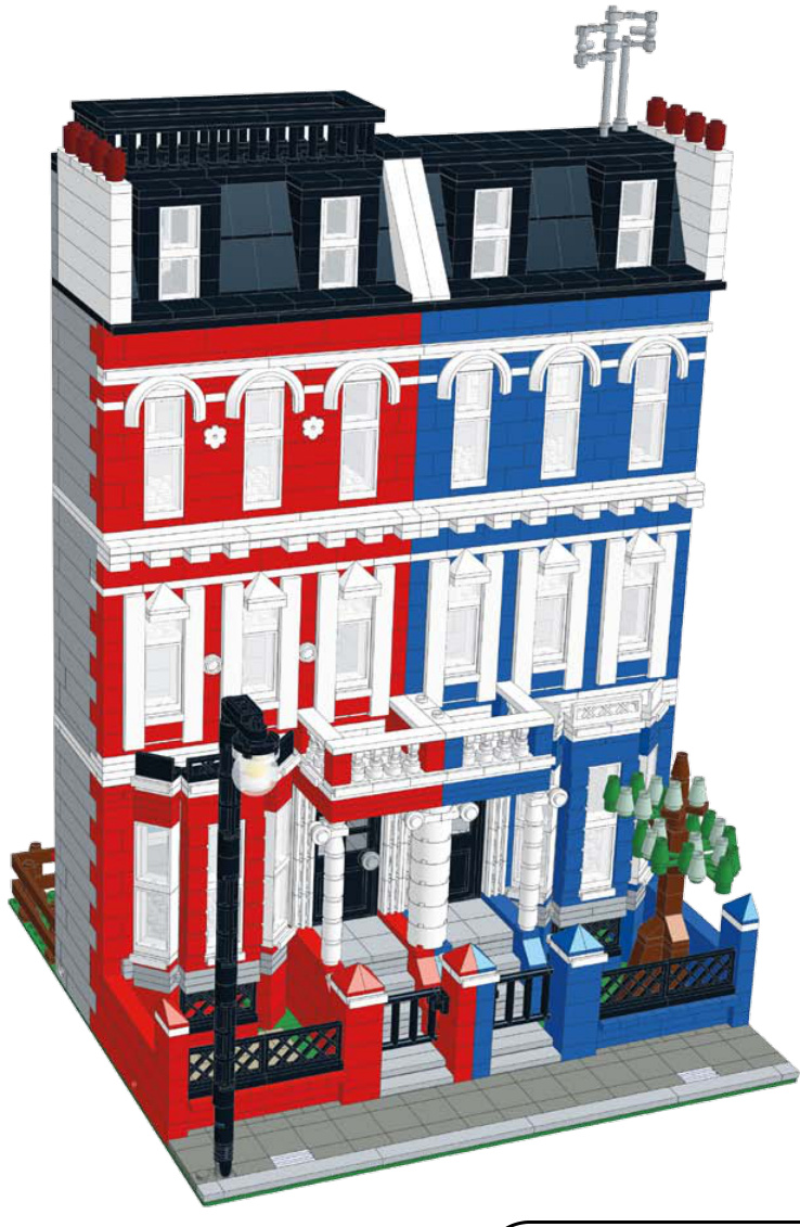
AccentColors
Great-looking LEGO buildings have one thing in common: they use color thoughtfully. Having a main color and accent colors can really help your model look cohesive and realistic.
When inventing your own color combinations, you can use the color wheel to help you determine what colors would look good together. Opposites (that is, colors across from each other on a color wheel) attract. The Internet is also full of tools for real-life homeowners planning to paint their houses’ exteriors. Different architectural styles often have common color schemes. Take advantage of any resource available to you while planning.
Let’s see how you can use accent colors to help bring the model alive.
The Design Process 11
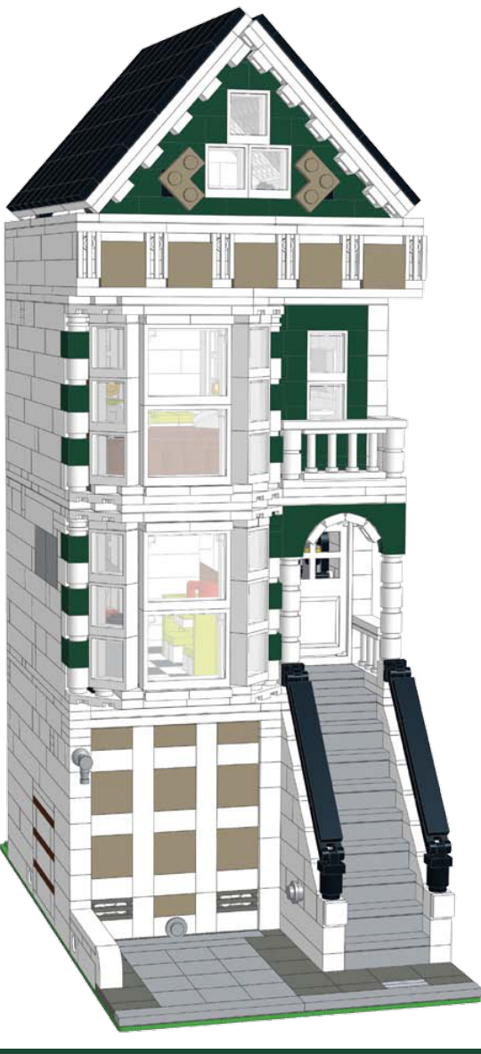
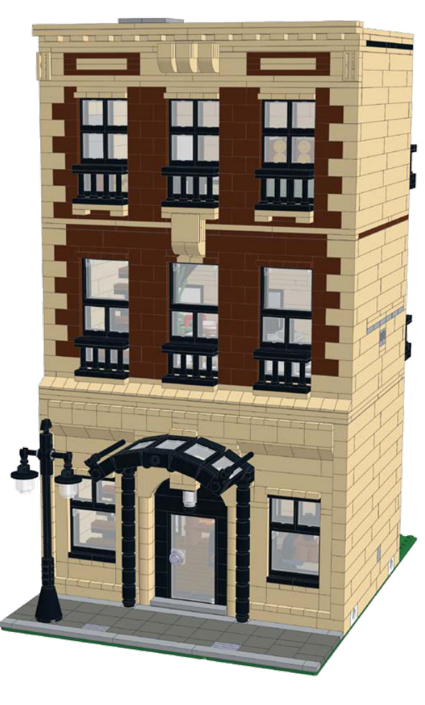
On this brownstone house, the main colors are tan and brown. The accent color is black, which you can see in the street lamp, awning, windows, and railings.
This row house uses dark tan for the garage door and roof area to help break up the dark green and white.
police station
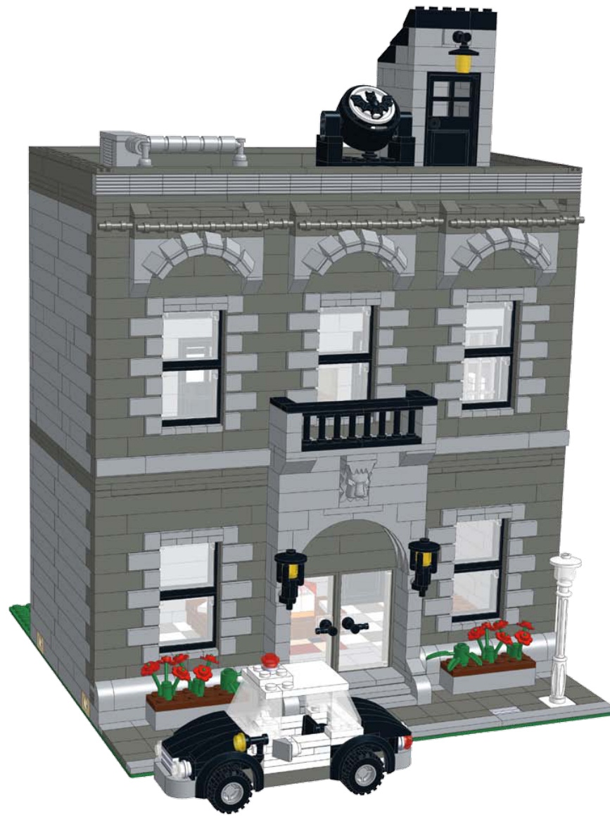
In this police station, black was used for the railing, windows, and light fixtures, while light bluish-grey was used in conjunction with dark bluish-grey to mimic stone.
Trim Color
One natural place to use an accent color is the trim of a building. While the realworld use of fancy trim and molding has definitely decreased over the years, it can still give your building some pizzazz. Choose a contrasting color, just like any other kind of accent color. White or wood-color is common.
Symmetry
Symmetry is important when it comes to architecture. On the facing page are some examples that illustrate symmetry in a building’s design.
Keeping the length of the bricks uniform on the front of the building can showcase a commitment to symmetry and enhance the look of the model.
You can apply the same rule of symmetry to tiles and plates. Taking the time to make a flawless, symmetrical facade goes a long way toward making your model look professional and complete.
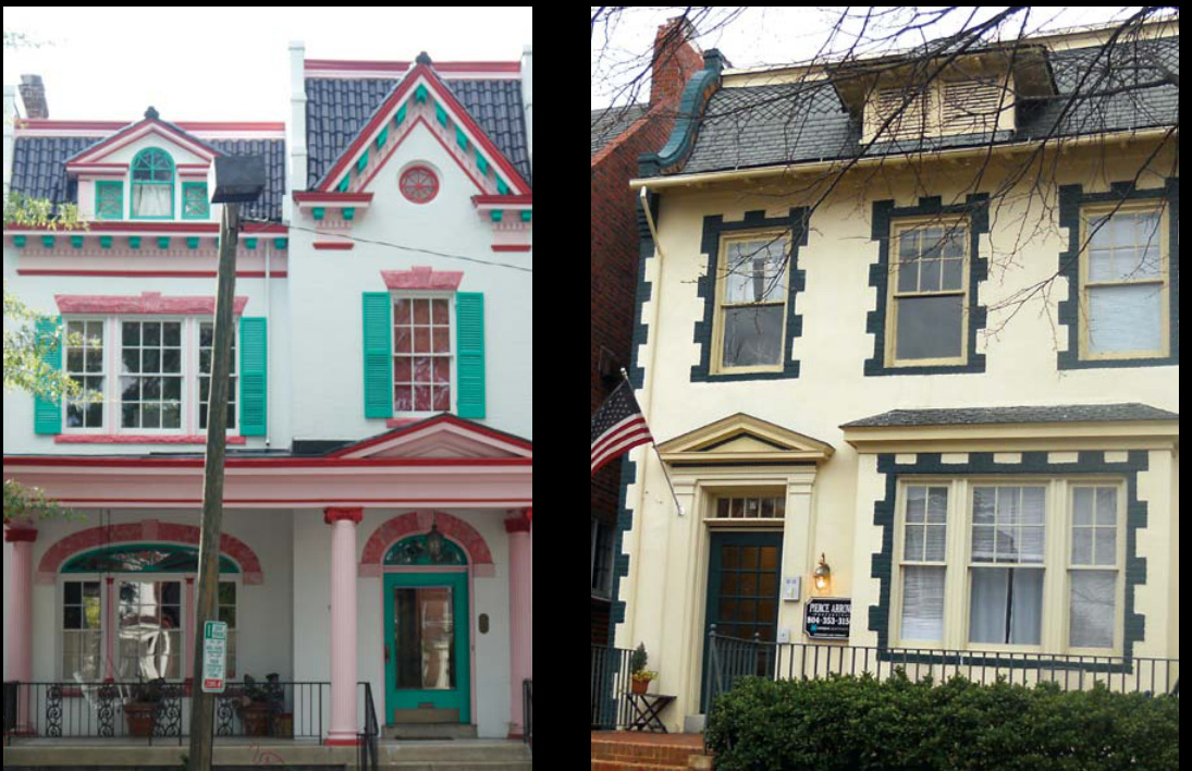
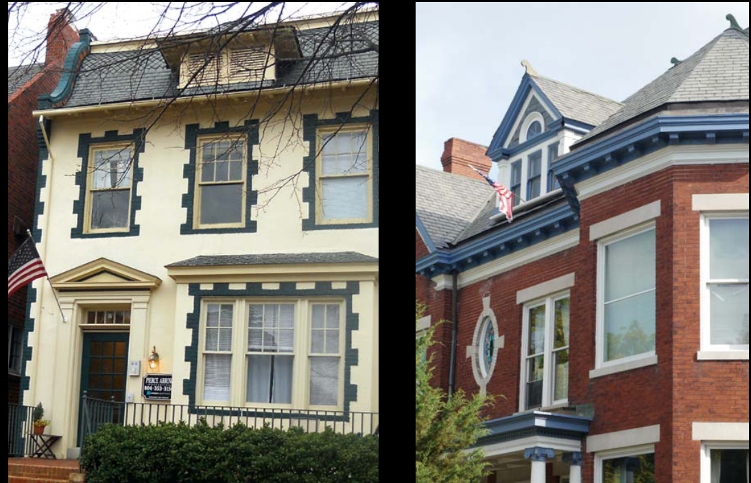
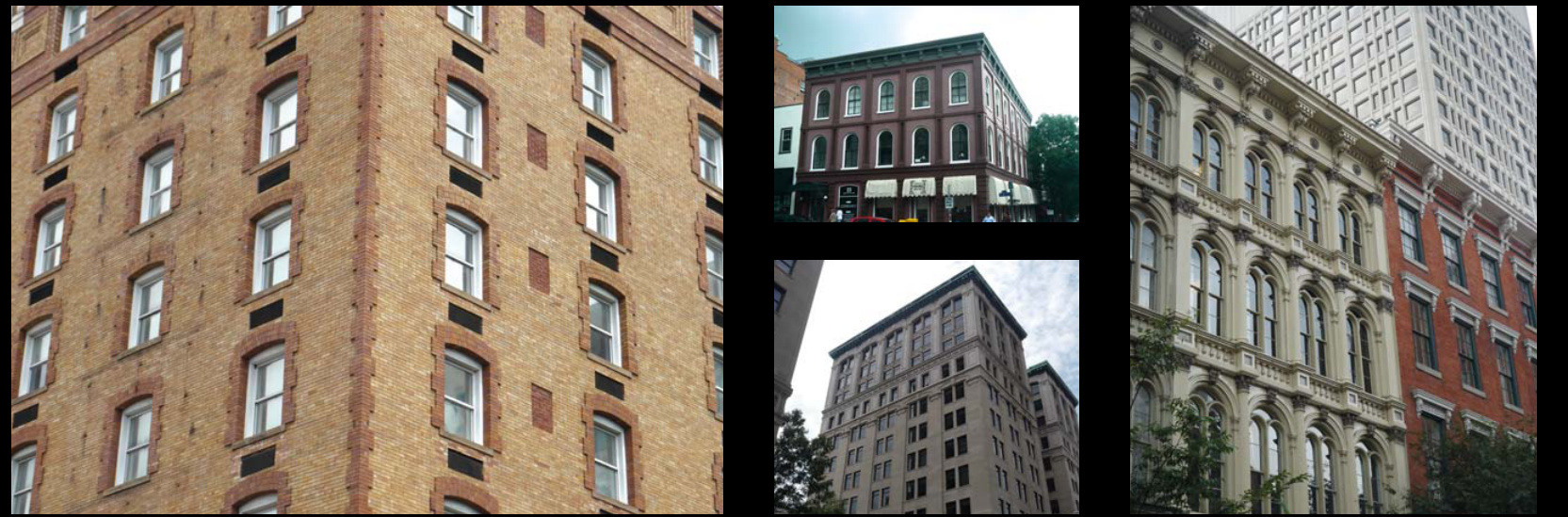
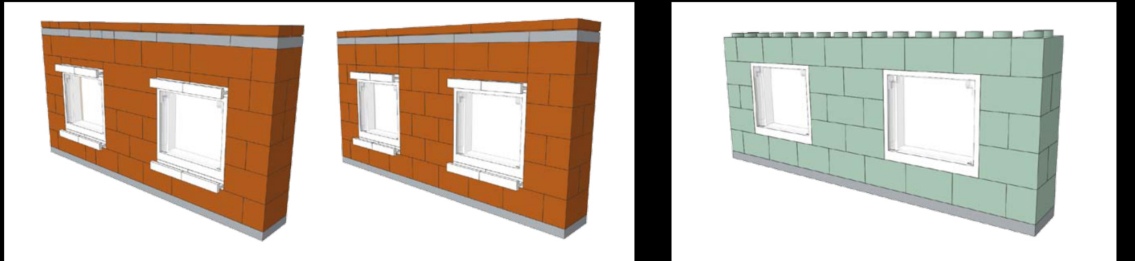
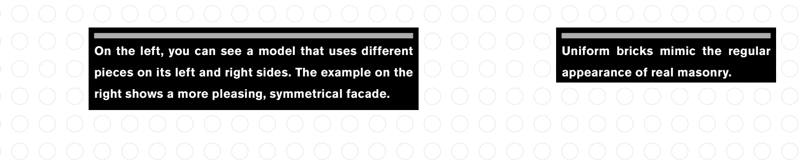
Get Started!
Just start building. You’re going to make mistakes along the way. You’ll make designs that look terrible and nothing like what you imagined or nothing like what you’re trying to copy. Don’t get discouraged. For every building we make that we like enough to use for instructional purposes, there’s another building we made that turned out horribly. Don’t forget about stepping away from the problem, too. We currently have 10 buildings set aside because there’s some aspect of each building that we haven’t figured out how to fix yet.
Sometimes when we get stuck with a part of a building, we will make that part of the model easily detachable. That way, we can build multiple versions of a section of the building and pop them on and off to see which version looks the best.
Probably the most important time-saving tip we can offer for the design process is to spend your time refining the facade until you’re happy with it. The facade is what faces the street, so it’s what gets seen first. If your building is sandwiched between other buildings in a display, the facade may be the only part of the building that shows. We’ve spent a lot of time building interiors, sidewalls, and rear walls on buildings that we ultimately abandoned because we couldn’t make the facade look like we wanted it to.
So now you have an idea, but are you unsure how to translate it into LEGO form? The next chapter discusses how to recognize pieces in the everyday world around us.
As you’re building, try to imagine the reallife reference building as a giant LEGO model. As crazy as that might sound, it will help you identify which architectural details actually look like individual LEGO pieces already. And on some projects, you will find a piece you just have to use, and this will help determine the scale of the model, too.
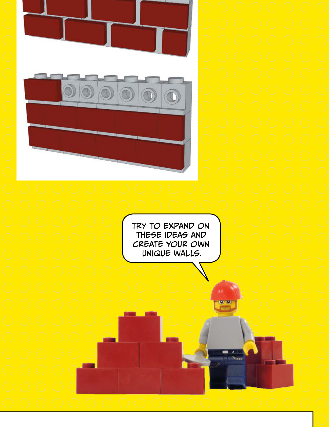
If the building is made of cement blocks, stones, or bricks, you might consider using bricks or only plates to give it a look that mimics real masonry. Above is an example of using bricks to model a brick wall.
There are other ways to create a simple brick wall, too. Check out the examples on the right.
window with an interesting frame
In the picture to the right, you can see a window with an interesting frame. How many pieces can you see right away? You can imagine those slopes and the grills at first glance. Of course, after you choose the pieces necessary to create an object, you’ll need to determine how to actually attach those pieces to a building.
On the side of this building, there are rows of bricks that have vertical grooves. The brick on the right immediately comes to mind.
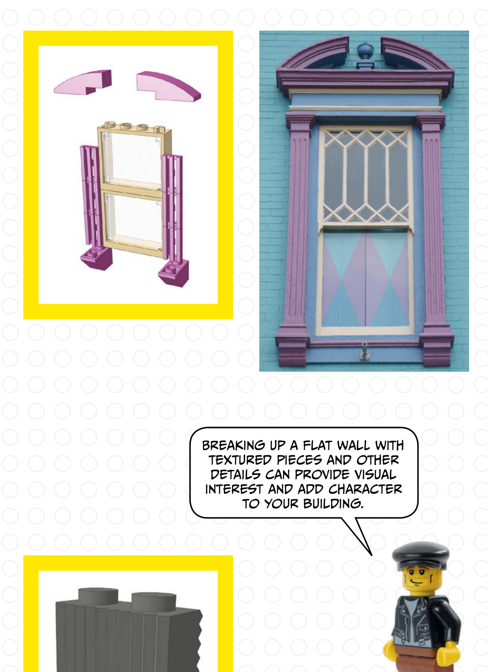
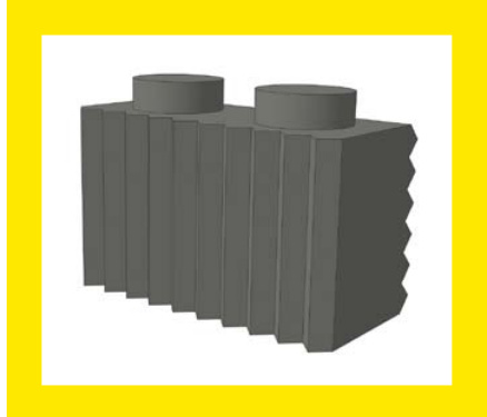

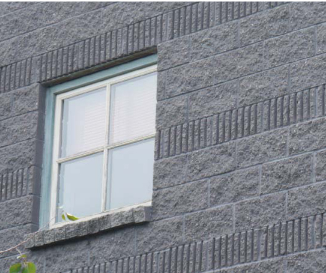
The slope and cone
The slope and cone at right nicely mimic the trim on this yellow house.
Some patterns might not be obvious at first. Check out the pattern on the right side of this wall. A similar look could be built with 2/3 slopes as shown.
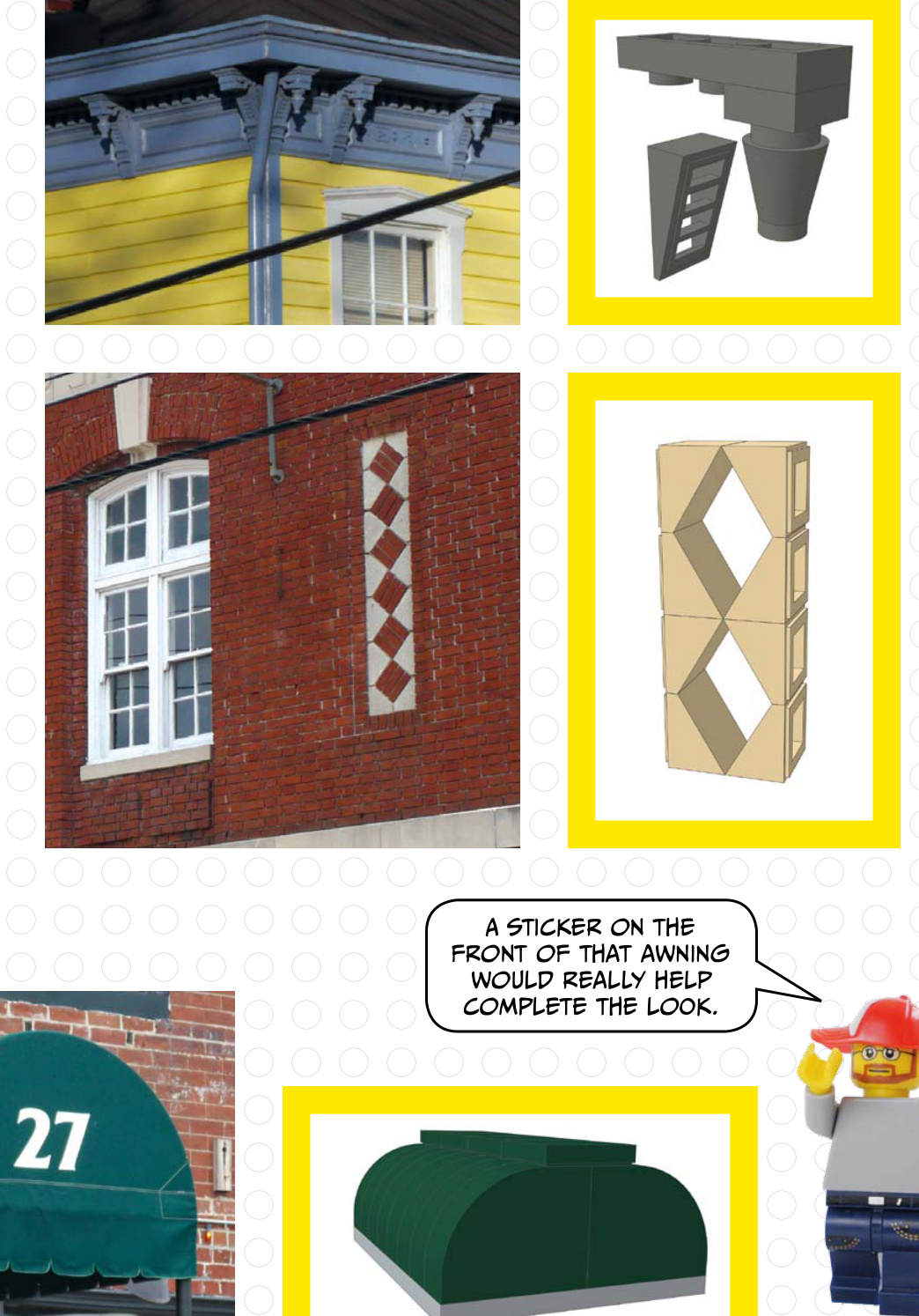
The green awning below has a curved shape. In the picture on the right, you can see the curved bricks that would match that shape.
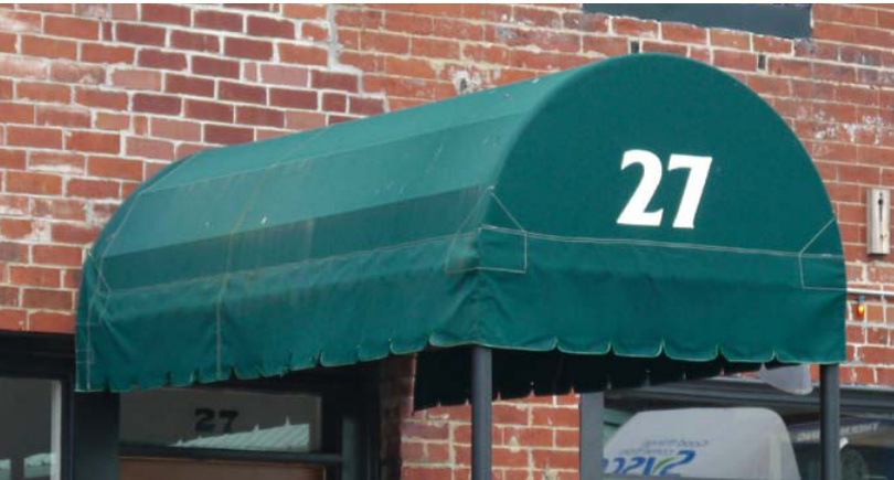
Several parts of this building immediately stand out, such as the white arch above the door and the door itself. The black grills could be used on a brick-built door, and this white arch matches up nicely.

The real-world house above was the inspiration for the model below.
This molding features shapes that look like flowers. This big flower is a good match.


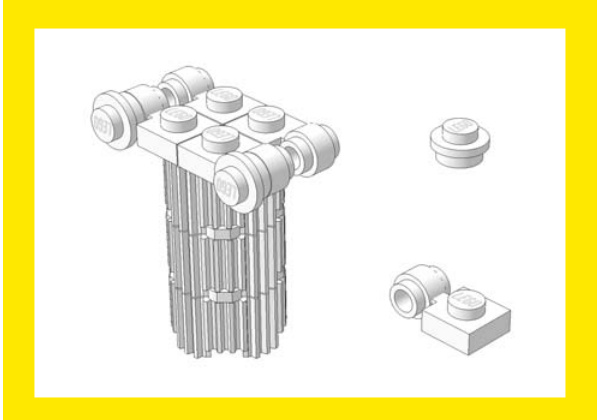
The top of this classic Ionic column has decorative corners, which you can emulate with two parts.
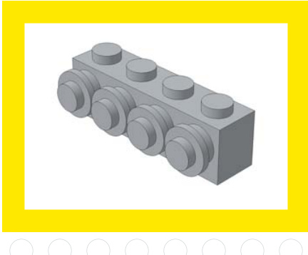
Between these windows is a decorative element that looks like a row of round plates.
curved windows
The arch over the curved windows shown here is an easy build: use a arch over a window with a round top. The white door rails at the bottom represent the window ledge.
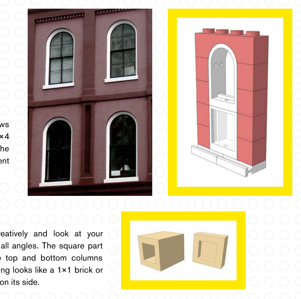
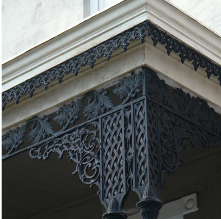
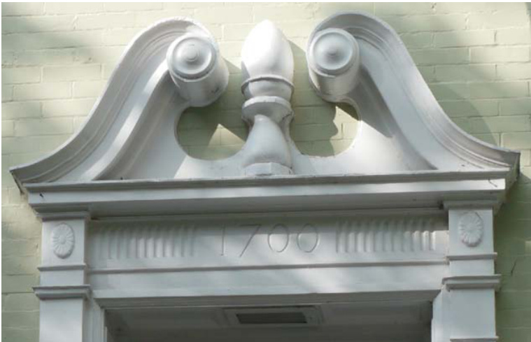
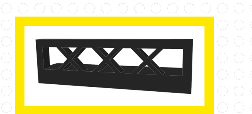
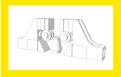
This detail work above this doorway looks complicated at first, but with the right pieces you can approximate the look.
under this window ledge

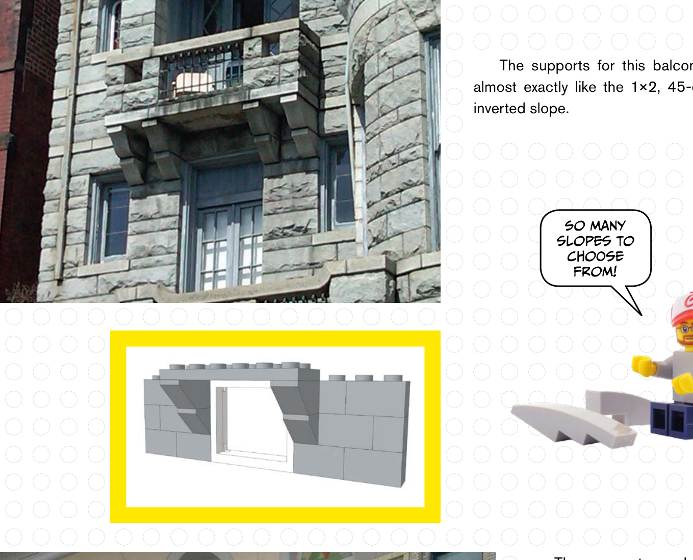
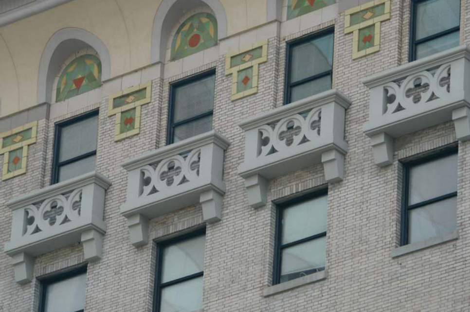
The supports under this window ledge feature slopes as well, but perhaps a studs not on top (SNOT) technique would look better here.

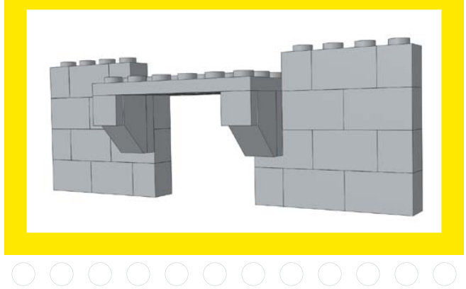

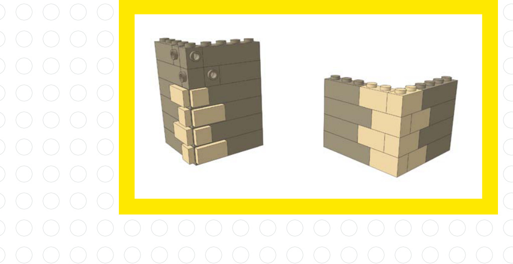
You could
make a larger
curved railing
using hinge
plates.
The railing in this example is obvious, but on the right side of the building you can see trim that looks like a LEGO plate turned on its side, facing outward.
This corner brick pattern looks like tiles attached to the side of the building. You could also achieve this look using only bricks.

The Details
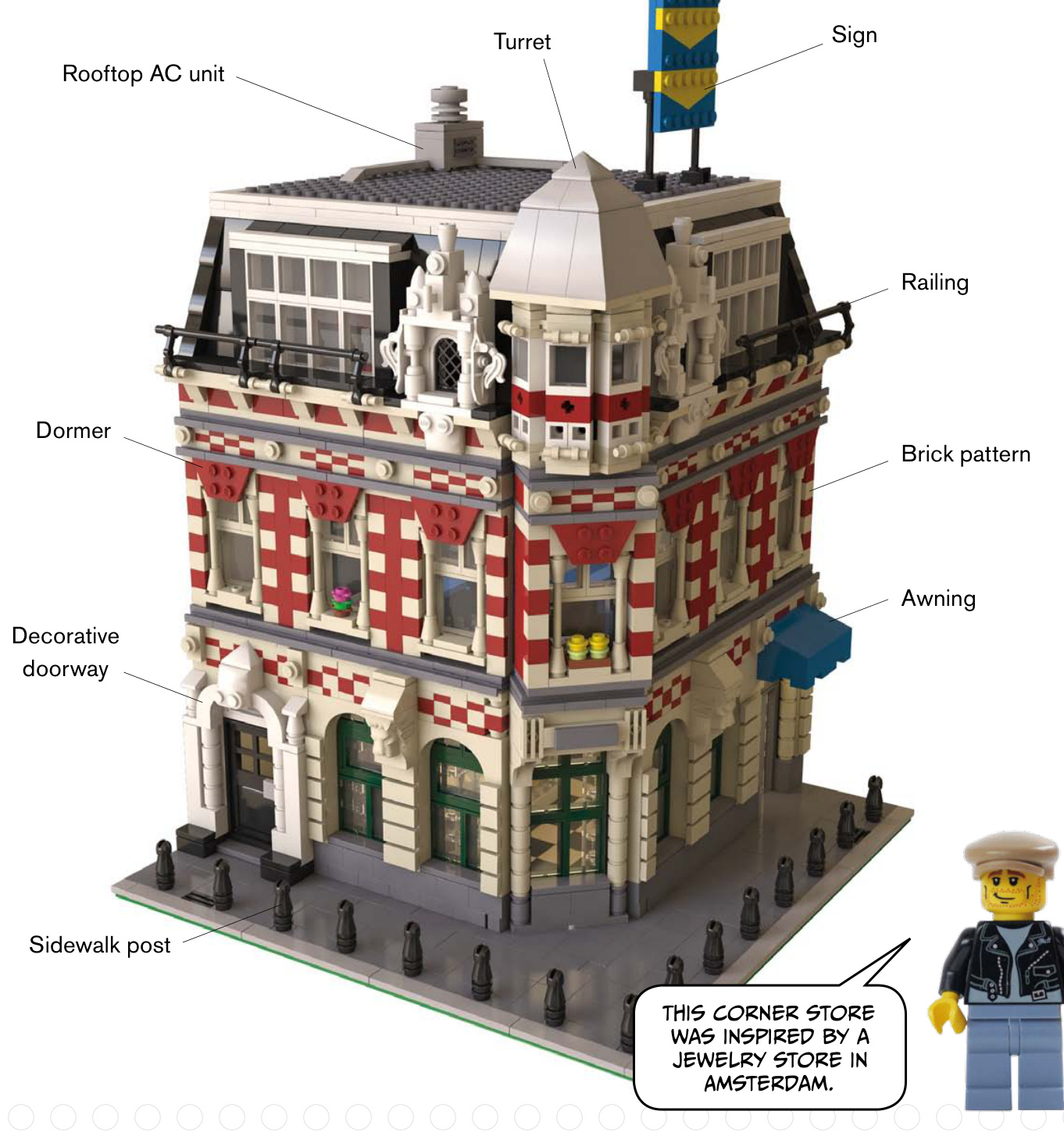


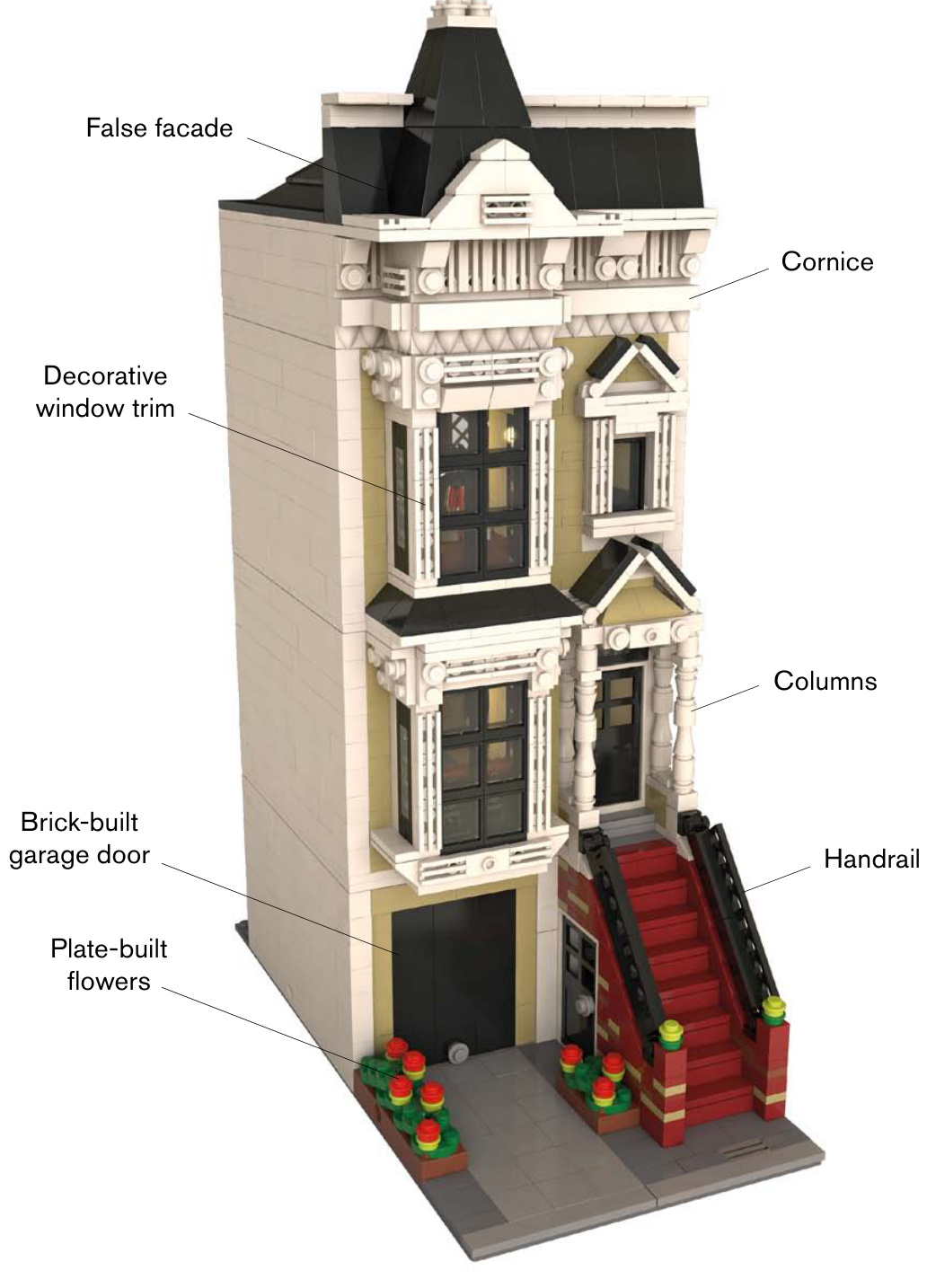

Roof Moldings
Here are a few examples of real-world trim molding along rooflines. Which pieces could be used to replicate these looks?
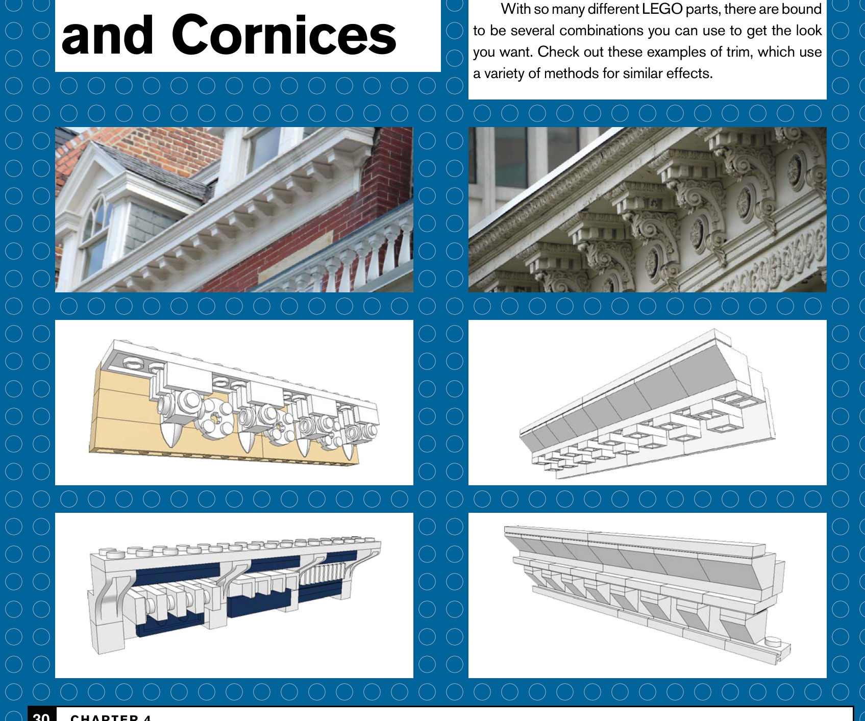
30 Chapter 4
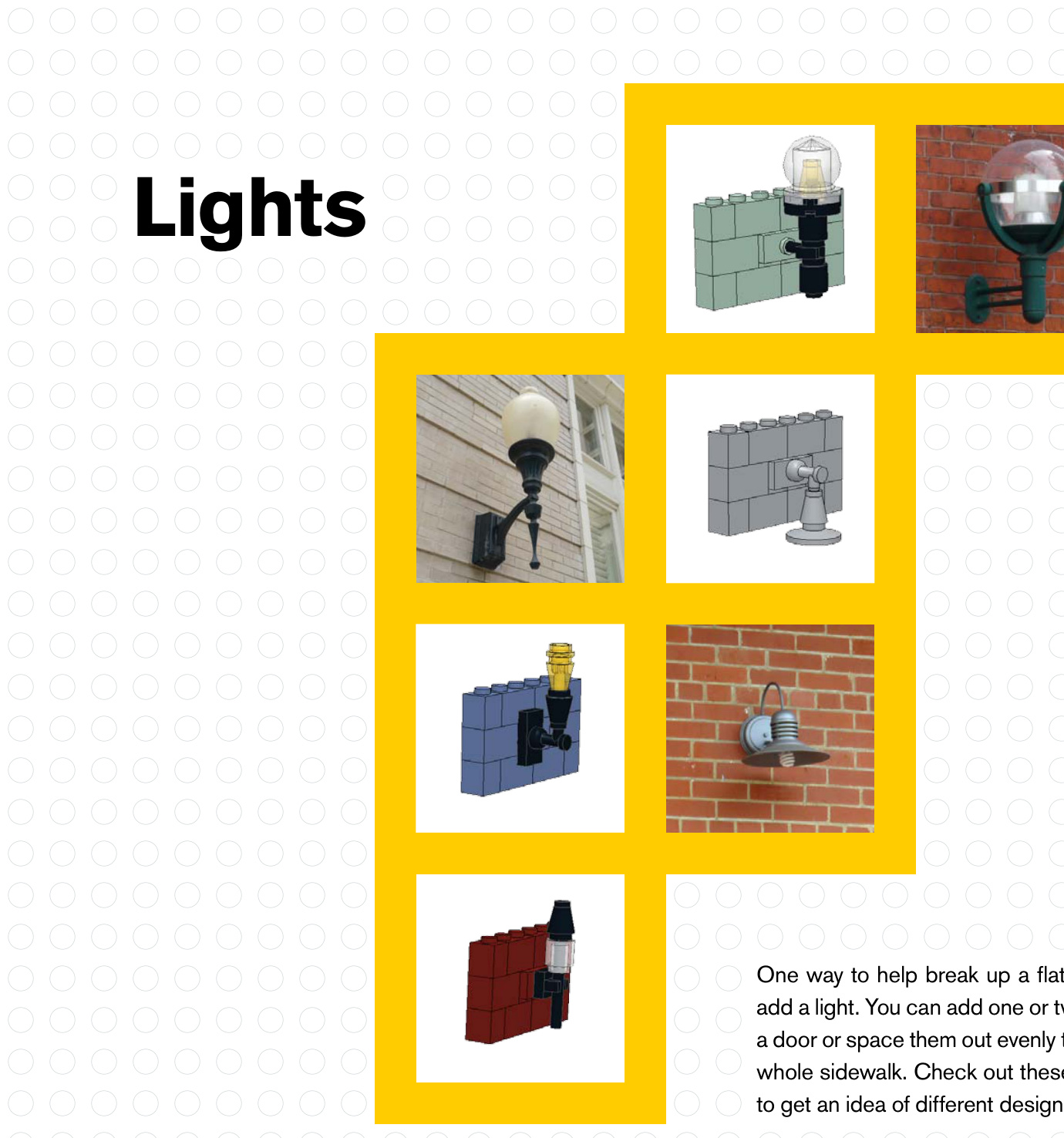

Columns and Railings
Look over these pictures and try to imagine which LEGO pieces you would use.
You can make columns any number of ways, from simple to complex (often using SNOT techniques).
Railings and fences can be very simple, or you can use more ornate pieces to create a balustrade.
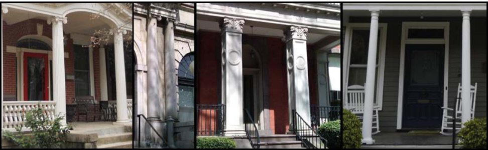
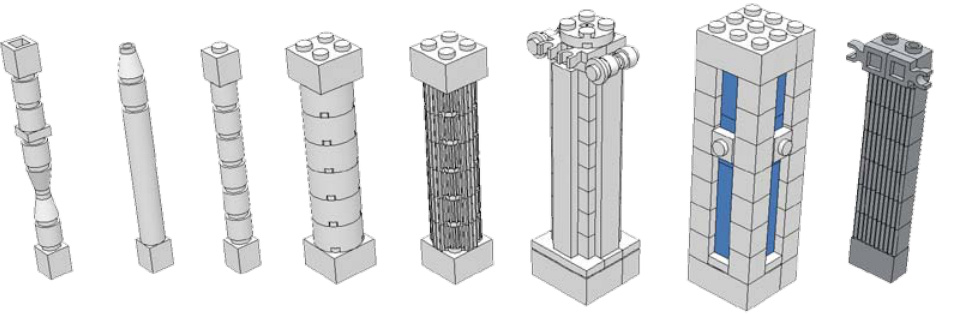
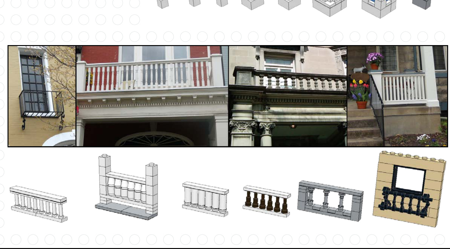
32 Chapter 4

Windows and Shutters
Windows are so important to a building’s look that architects sometimes call them “the eyes” of a structure. Check out these examples of how to create vastly different looks by using various pieces in and around the windows.
For a long time, LEGO made windows that had shutter tabs that could hold shutter pieces. More recent window pieces don’t have those built in, but you can still make shutters using other elements.
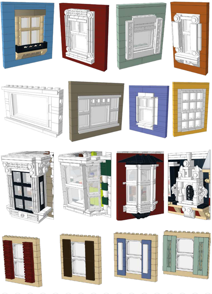
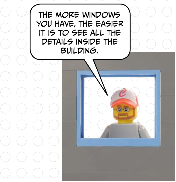
Plant Life
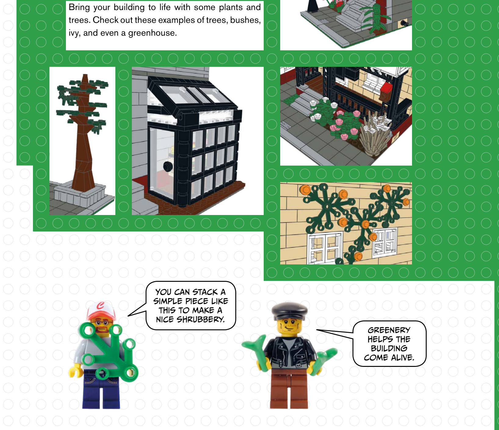
Newspaper Racks
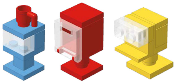
Take a walk down a typical sidewalk, and you’ll see there is a lot more than just flat, grey cement. Adding real-world details can give your building even more flair.
Usually you see these newspaper or magazine dispensers grouped together on street corners.
Here are a few examples of how to make a fire hydrant. You can mix up the colors to match a certain city that you are trying to copy.


Parking Meters
ters to line city? Here ome.